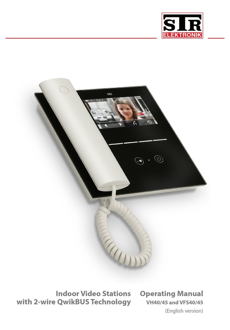
STR Electronik DBM40 User manual

Operating Manual
DBM40
(Translation of the original
instructions)
Display Module Door Station
with 2-wire QwikBUS Technology

Legal information
Document Type: Operating Manual
Product: Display Module Door Station with 2-wire QwikBUS Technology, DBM40
Target audience: Authorized technicians
Language: English
DocumentNumber_Version:
Publication date: 08/2014
Publisher/Manufacturer
STR Elektronik
Josef Schlechtinger GmbH
Auf dem Ohl 9, D-57482 Wenden, Germany
© STR Elektronik Josef Schlechtinger GmbH
Reproduction of this manual, in whole or in part, is permitted only
with the written consent of Joseph Schlechtinger GmbH.
All product names mentioned in this manual are trademarks of the
respective companies.
The information in this document is subject to technical changes.

3
Operating Manual DBM40 - 08/2014
Table of Contents
1 General 4
1.1 How to use the operating manual 4
1.2 Symbols used 4
1.3 Copyright 5
1.4 Warranty 5
1.5 Applied standards 5
2 Security 6
2.1 Proper use 6
2.2 General hazards 6
2.3 Electrical hazards 6
2.4 Maintenance and repair work 6
3 Structure and function 7
3.1 Package contents 7
3.2 Structure and function of DBM40 7
4 Installation and wiring 9
4.1 Safety instructions for installation and wiring 9
4.2 Important information 10
4.3 Wiring 10
4.4 Installation 13
5 Programming and operation 14
5.1 General information 14
5.2 Programming the device with DBM40 Editor 14
5.3 Programming on the DBM40 21
5.4 Operation 23
6 Errors 25
6.1 Troubleshooting safety 25
6.2 Error causes and troubleshooting 25
7 Removal and disposal 26
7.1 Removal safety 26
7.2 Removal 26
7.3 Disposal 26
8 Technical information 27
8.1 Display Module Door Station DBM40 27
9 Appendix 28
9.1 Accessories 28

General
4
Operating Manual DBM40 - 08/2014
1 General
1.1 How to use the operating manual
This operating manual describes the safe and ecient handling of your
STR Display Module Door Station.
It is part of the package contents and must be kept accessible to the user
at all times.
Due to technical developments, the illustrations and descriptions in this
manual may dier slightly from the actual Display Module Door Station
delivered.
We assume no liability for damage caused by non-observance of these
operating instructions.
1.2 Symbols used
All safety information in this manual is identied with appropriate
symbols. The signal words preceding the safety information express the
potential extent of the hazard.
DANGER!
This symbol/word combination indicates an imminently hazardous
situation that will result in death or serious injury if not avoided.
WARNING!
This symbol/word combination indicates a potentially hazardous
situation that could result in death or serious injury if not avoided.
CAUTION!
This symbol/word combination indicates a potentially hazardous
situation that could result in minor injury if not avoided.
IMPORTANT!
This symbol/word combination indicates important information that
can help avoid physical or environmental damage.

General
5
Operating Manual DBM40 - 08/2014
1.3 Copyright
This manual and all documentation supplied with this unit remain the
copyrighted property of STR.
Their use is permissible and desirable only for the purpose of operating
the device.
This documentation may not be reproduced or made available to third
parties, especially our competitors, without the express permission of STR.
1.4 Warranty
The manufacturer guarantees the product in accordance with the terms
and conditions of purchase and delivery. The warranty is void if:
> damage is caused by improper handling,
> repairs or modications are performed by unauthorized personnel,
> non-STR accessories or replacement parts are used
> defective components are not repaired immediately in order to limit
the extent of the damage and avoid compromising the safety of the
equipment (maintenance obligation).
1.5 Applied standards
The following European and national standards were applied in develop-
ing and manufacturing the Display Module Door Station:
> VDE 0860 - Audio, video and similar electronic devices
- Safety requirements
In assessing the risks posed by the device, the following standards, BGV
(accident prevention guidelines issued by the employers' liability insur-
ance associations in Germany), BGR (rules supplementing the BGV) and
BGI (additional information regarding the BGV) were applied:
> VDE 0100
> VDE 0800
> VDE 0805
> Health and safety regulations (VSG)
> Accident prevention regulations (UVV)

Security
6
Operating Manual DBM40 - 08/2014
2 Security
2.1 Proper use
The Display Module Door StationDBM40 provides access control and
communication between the front door of a building and the residences
or oces inside. It is therefore ideal for use in apartment buildings, dormi-
tories and public facilities.
Any other use is considered improper.
Proper use includes observance of this manual.
2.2 General hazards
There are general risks involved in dealing with electrically powered
devices. Therefore, please observe the legal requirements for health and
safety (VSG) as well as any other generally recognized health and safety
rules and accident prevention regulations (hereafter referred to as UVV).
Do not make any changes to the Display Module Door Station. The manu-
facturer is not liable for damage caused by improper modications.
2.3 Electrical hazards
When installing the device, be sure to note the prescribed values for volt-
age and amperage (see technical data).
Only qualied electricians may work on the electrical system or the con-
trol system.
Unplug the power cord before beginning work.
Regularly inspect the plug and power cord and have them replaced by a
qualied electrician if damaged.
2.4 Maintenance and repair work
Maintenance and repair work may only be performed by authorized
personnel. These are persons who are authorized on the basis of their
education, training or experience to perform the required tasks and to
recognize and avoid possible dangers. They must be able to provide proof
of knowledge of the relevant safety standards, regulations and accident
prevention rules and have read the manual.

Structure and function
7
Operating Manual DBM40 - 08/2014
3 Structure and function
3.1 Package contents
The Display Module Door Station is delivered with the following items:
• the DBM40 module
• a PC cable with a 7-pin plug
• a DBM connection module (computer terminal board)
• a mini-CD containing the programming software and
• these operating instructions.
3.2 Structure and function of DBM40
The Display Module Door Station consists of a 3.5 inch TFT display and
three operating buttons.
Fig. 1:
1
2
3
4
Structure of the Display Module Door Station
1 3.5" TFT screen for displaying information
2 "Up" button
3 "Down" button
4 "Conrm" button

Structure and function
8
Operating Manual DBM40 - 08/2014
Fig. 2:
1
2
3
Structure of the Display Module Door Station
1 Interface for connecting to TSMB3 or TT33-3 (adapter required); 6-pole
2 Interface for service (programming of the rmware during production); 7-pole
3 Interface for optional external keypad; 8-pole
Special features DBM40
Programming directly on the device or with PC soft-
ware via USB and SD card
x
Operation via three buttons directly on the module x
Operation via external keypad (optional) x
Customizable background image (2.16 and 256 colors
bitmap graphic, max. 320 x 180 pixels)
x
Up to 500 entries in DBM40 x
256 colors (RGB332) x
Function
The STR Display Module Door StationDBM40 provides access control and
communication between the front door of a building and the residences
or oces inside. It is especially suitable for complex projects such as large
apartment buildings, dormitories and public facilities.
It is operated via three buttons on the module or optionally via an exter-
nal keypad.

Installation and wiring
9
Operating Manual DBM40 - 08/2014
4 Installation and wiring
4.1 Safety instructions for installation and wiring
The STR Display Module Door Station should only be installed and wired
by authorized personnel with the appropriate knowledge and training.
The general safety requirements for telecommunications equipment
(VDE800) must be observed.
DANGER!
Risk of death from electrocution!
Contact with live terminals may lead to serious injury.
Turn o the power supply.
Secure the power supply to prevent it from being turned back on.
IMPORTANT!
Possible damage to property from improper installation!
Voltage from the public power grid supplied to the wrong terminals
on the device may damage the electronics.
Do not connect low voltage terminals to the public power grid.
IMPORTANT!
Possible damage to property from improper installation!
Overly stripped wires may result in short circuits and damage to the
electronics if a wire strand accidentally comes loose.
Strip cables only to the extent necessary to prevent a short circuit,
but not more than 3 cm.
Route the cables properly.
Use cable grips to prevent pulling.
IMPORTANT!
Possible damage to property from electrostatic charging!
Electrostatic charging may cause devices to be destroyed through
direct contact with printed circuit boards.
Discharge yourself before touching the device.

Installation and wiring
10
Operating Manual DBM40 - 08/2014
IMPORTANT!
Possible damage to property from improper cable routing!
High and low voltage lines must be kept separate to avoid interfer-
ence on the lines.
Surface and concealed wires must be spaced at least 10 cm (4 inches)
apart.
In installation channels, a barrier strip separating high and low volt-
age lines must be used.
4.2 Important information
> The optimal installation height for the Indoor Video Station is about
1.50 m (5 ft).
> Choose a location out of direct sunlight.
> The optimal intercom distance is about 30 cm (12 inches).
4.3 Wiring
Use commercially available communication lines (such as J-Y (St) Y, J-2Y (z)
Y) for running the bus lines.
IMPORTANT!
Possible damage to property from improper installation!
Induced voltage peaks may cause malfunctions.
The SP333 controller may not be installed in the immediate vicinity
of strong magnetic elds (transformers, contactors, etc.).
Maximum cable lengths:
Wire diameter in mm (AWG) Audio in m (ft) Video in m (ft)
0.6 (22) 150 (500) 75 (250)
0.8 (20) 300 (1000) 150 (500)
1.0 (18) 450 (1500) 225 (750)

Installation and wiring
11
Operating Manual DBM40 - 08/2014
Fig. 3:
CN2
TSMB3-AM
Tö
BUS
Tö
ET BUS
BUS
ET
ET BUS
ET
TSMB3
12V~
ST5
TSMB3
Keyboard
PC
Reset
SD-Card
Keyboard (optional)
connect to Keyboard-
connector at the
rear side of DBM40
DBM 40
EEPROM
USB
SP333
12V~
24V
Tö1
BUS BUS
12V~
SNT333S
-24V+
+-
NTR201
230V AC
0
230V AC
DBM40-AM
ST1
Door opener
can connect at
SP333 or alternative
at TSMB-3 (DIP-3 „ON“)
TSMB-3
CN2
CN1
Wiring diagramm DBM40 with TSMB-3
~
~
DBM40- back
TSMB-3 back
Wiring of DBM 40 to TSMB3

Installation and wiring
12
Operating Manual DBM40 - 08/2014
Fig. 4:
CN2
Tö
BUS
TOE
ET BUS
BUS
ET
ET BUS
ET
12V~
TSMB3
Keyboard
PC
Reset
SD-Card
DBM 40
EEPROM
USB
SP333
12V~
24V
Tö1
BUS BUS
12V~
SNT333S
-24V+
+-
NTR201
230V AC
0
230V AC
DBM40-AM
CN2
CN1
Wiring diagram DBM40 with TT33-3
~
~
12V~
DBM40/TT
TT33-3
DBM40 back
TT33-3 back
Keyboard (optional)
connect to Keyboard-
connector at the
rear side of DBM40
Door opener
can connect at
SP333 or alternative
at TSMB-3 (DIP-3 „ON“)
Wiring of DBM 40 to TT33-3

Installation and wiring
13
Operating Manual DBM40 - 08/2014
4.4 Installation
Fig. 5:
1
2
3
Installation of DBM40 in the Varoex module system
> Insert the 6-pin connector for connecting to the TSMB3 or TT33-3
(adapter required).
> Connect the power supply (12 VAC) to the TSMB3-AM.

Programming and operation
14
Operating Manual DBM40 - 08/2014
5 Programming and operation
5.1 General information
The Display Module Door Station can be programmed for initial use in
various ways:
• on a PC with a data cable connected to the DBM40
• on a PC with a microSD/SDHC card
• on the DBM40 itself using the three buttons
You can program the device from a PC using the DBM40 Editor software.
The software is found on the mini-CD delivered with the device.
An SD card is not included. The following cards can be used:
> microSD cards 8 MB to 2 GB
> microSDHC cards 4 GB to 32 GB
The instructions for programming the device from a PC using the software
are described below.
5.2 Programming the device with DBM40 Editor
The DBM40 Editor can be used to fully manage the display. All settings
as well as the database can be stored in a so-called project le and re-
opened later. Data can be uploaded to the DBM40 via a USB connection
(USB adapter required) or an SD/SDHC card.
Fig. 6: DBM40 Editor start screen

Programming and operation
15
Operating Manual DBM40 - 08/2014
Creating a new project
> Start the software by double-clicking the icon.
> Select the language (German/English).
> Click the New button.
A window appears: Would you like to use the Project Wizard?
The Project Wizard makes creating a new project easy by letting you pre-
congure various settings such as the number of entries, prex, last name,
rst name, personal information and project name.
If you choose not to use the Project Wizard, an empty database with a
single entry will appear.
Fig. 7: Creating a new project (with the Project Wizard)
> Fill in the elds for each individual unit by selecting the row for the unit and
changing the entry using the keyboard:
• No. (= memory entry number)
The memory entry number is preassigned by the system. It corre-
sponds to a memory entry on the intercom.
If alphabetical sorting is turned o on the DBM40, the entries will ap-
pear on the device screen in order by their memory entry number.
• Prex
Prex is an optional eld (maximum 16 characters) that appears before
the resident's last name. It can used for titles such as Dr., Mr., Ms., etc.
The Prex eld is ignored in alphabetical sorting.
• Last Name
The Last Name eld is required. The last name may contain up to 24
characters. Note: The 24-character limit is shared between the Prex,
Last Name and First Name elds.
If alphabetical sorting is activated, the entries will be sorted by Last
Name. If alphabetical grouping is activated, entries will be grouped
based on the rst letter of the last name.

Programming and operation
16
Operating Manual DBM40 - 08/2014
• First Name
First Name is an optional eld (maximum 23 characters) that is dis-
played after the last name following a comma. The First Name eld is
ignored in alphabetical sorting.
• Personal Information
Personal Information is an optional eld (maximum 47 characters) for
storing miscellaneous information.
This information can be displayed while a unit is being called as well as
during the conversation. It may include, for instance, the doctor's oce
hours or the times the reception desk is available.
• Unit Information
Unit Information is an optional eld (maximum 47 characters) for stor-
ing miscellaneous information.
This information is displayed whenever the door release is activated.
If the call recipient activates the door release, the door release symbol
appears and Personal Information switches to Unit Information. Unit
Information can be used to tell the visitor how to nd the unit or what
oor it is on.
• Unit No. Unit No. is only important if an optional external keypad is
installed. It contains a maximum of 4 characters and must be unique;
i.e. multiple units cannot be assigned the same number.
If the external keypad is connected, the visitor can call a unit by simply
entering the unit number directly from standby (such as "123") and
pressing the bell symbol, without having to search for the particular
entry in the list.
• Door Code
The door code can be used to trigger the door release and unlock the
door. The door code can only be entered using the external keypad.
The code must be a 4-digit number. For increased security, the door
code is linked to the unit number. For example, if the door code for
Unit 123 is 0815, the full code that must be entered is 1230815.
The door code can be entered while the device is on standby by rst
pressing the C key on the external keypad. The DBM40 will then ask
you to enter the door code. To keep bystanders from seeing the code,
shortly after each key is pressed, the number is replaced by an *. Once
you are done entering the code, press the bell button. The DBM40 will
verify the code and trigger the door release.

Programming and operation
17
Operating Manual DBM40 - 08/2014
• Active
If an entry is deactivated, it will no longer appear on the list of entries.
However, if a unit number is associated with that entry and an external
keypad is installed, you can still select the entry by entering the unit
number on the keypad. This is useful for residents who do not wish to
have their name publicly displayed.
• Special Entries
Up to three Special Entries may be stored on the DBM40. These entries
will appear at the top of the list (regardless of whether alphabetical
sorting is activated). For example, if you want "Main Oce" to always
be listed rst, you can make Main Oce a Special Entry.
To do so, enter "!1", "!2" or "!3" in the Prex eld. Each of these des-
ignations may appear only once on the list. The number next to the
exclamation point indicates the priority of the entry. If the Prex eld
contains a Special Entry designation, it may not contain any other
information. "!1" will appear as the rst entry on the list.
You can add or delete entries by clicking the +or -buttons.
Note:
A last name must be entered for each entry. This eld may not be left
blank.
You can also congure the following settings from this menu:
Fig. 8: Additional menu settings
• Activate/deactivate all entries
See Active; applies to multiple or all entries here
• Standby Image
You can select a standby image for each project. The image can be
bitmap with 2, 16 or 256 colors with a maximum width of 320 pixels
and a height of 180 pixels.

Programming and operation
18
Operating Manual DBM40 - 08/2014
> Click Load Image.
You can now select an image from your hard drive. To delete the image,
click Delete Image.
• Conguration
Text Size
You can choose between small, normal and large text.
Language
The following languages are available: German, English, French, Italian,
Turkish, Dutch, Norwegian, Spanish
Check boxes:
Show image: If a microSD/SDHC card with a valid standby image is
inserted, you can choose whether to display the image on the card. If
this box is not checked, the word "Welcome" will be displayed.
Group alphabetically: If this box is checked, the system will rst ask
you whether you wish to "Select Alphabetically" or "Show All". If the
box is unchecked, all entries will automatically be displayed.
Sort alphabetically: If checked, all entries will be sorted by Last
Name. If unchecked, entries are shown in the order in which they were
entered.
Key sounds: If checked, a sound will be made every time you press a
key on the TSMB3.
Show unit no.: If checked, the unit number will be displayed in the list
of residents as well as whenever a unit is called. If not checked, the unit
number will not be displayed.
Show call direction: If checked, the device will indicate whether the
user is currently speaking or listening. If unchecked, a picture of a lifted
handset will appear indicating that a voice connection has been estab-
lished with the unit.
• Adjust color:
Up to 256 colors can be displayed on the device screen. The user can
adjust three color settings:
Selected entry color
Text color and
Background color
Each color can be adjusted via the slider or color chart.

Programming and operation
19
Operating Manual DBM40 - 08/2014
Data synchronization
Data can be synchronized via a USB connection or SD/SDHC card. A USB
connection is recommended.
Because of the large amount of data, the USB connection is divided into
three sections: Database, Conguration and Image.
Fig. 9: Data synchronization
• Read Database [USB]
This button establishes a USB connection to the DBM40 and reads the
entries from the database.
• Send Database [USB]
This button establishes a USB connection to the DBM40 and overwrites
the existing entries on the DBM40 with the entries from the DBM40
Editor.
• Read Conguration [USB]
This button establishes a USB connection to the DBM40 and reads the
conguration settings.
• Send Conguration [USB]
This button establishes a USB connection to the DBM40 and overwrites
the existing conguration with the settings from the DBM40 Editor.
• Read Image [USB]
This button establishes a USB connection to the DBM40 and reads the
standby image (if there is one).
Note:
It may take up to 15 minutes to transfer the image depending on the size.

Programming and operation
20
Operating Manual DBM40 - 08/2014
• Send Image [USB]
This button establishes a USB connection to the DBM40 and sends the
new standby image.
Note:
It may take up to 15 minutes to transfer the image depending on the size.
• Send [SD card]
This button saves the database, conguration and standby image to an
SD/SDHC card.
You can use this card to import and apply the data via the Service
menu on the DBM40.
• Read [SD card]
This button reads the database, conguration and standby image for
the DBM40 from an SD/SDHC card. However, you must rst synchro-
nize the card with the DBM40. You can do this from the Service menu
on the DBM40 under "Manage Database."
Saving and opening a project
The project can be saved and re-opened later.
> In the Database eld, enter a name for the project, such as "DBM40_Sam-
ple".
> Click Save.
You can now select the location on the hard drive where you would
like to save the project. The project will be stored there under the name
you entered plus the le extension .prj. The project le contains the
complete database, conguration and standby image.
> To open a saved project, click Open. Select the project le you wish to
open. The project is loaded and can be further edited.
Table of contents
Other STR Electronik Intercom System manuals
Popular Intercom System manuals by other brands
Bticino
Bticino 313271 instruction sheet

Batavia
Batavia 7062072 operating instructions

DTS
DTS Icom2 Operating instructions manual
SSS Siedle
SSS Siedle ZT 811-01 Product information
Alpha Communications
Alpha Communications TekTone Tek-ENTRY installation instructions
DoorBird
DoorBird A1061 Series installation manual
