IL487 Tek-ENTRY®with PK543 • Page 3
SIGNALFLOWANDTHEORYOFOPERATIONFOR
PK543 AMPLIFIER AND APARTMENT INTERCOM SYSTEM
The following example describes an Apartment Intercom
System using a PK543 Amplifier and is based on a 4-Wire
Intercom Station.
Call Button
PressinganapartmentCALL buttonontheentrypanelroutes
the call tone from the PK543 Amplifier’s terminal ZW
(or Z), through the apartment button being depressed, to
theTone In (X) terminal on the apartment intercom station
being signaled. This tone passes through the intercom
station’s speaker and returns on Common (1). The tone is
heard at the intercom station—and if dipswitch 3 is in
the ON position—at the entry panel. (Applies to warble
tone only.)
Talk Button
Pressing the TALK button at an apartment intercom station
connectsaudiofromtheintercomstation’sspeakerthrough
the intercom station’s terminals 1 and 2, to the PK543
Amplifier’s terminals 1 and 2. This audio is amplified and
outputon the amplifier’s terminalsAand G.The amplified
audio is then routed to entrance panel’s speaker/
microphone. The result is that someone speaking at the
apartment intercom station is heard at the entrance panel.
In 3-wire apartment intercom stations, audio to and from
the intercom station is between terminals 1 and 5.
Listen Button
Pressing the LISTEN buttonatanapartmentintercomstation
connects the speaker of the intercom station to terminals
1 and 3 of the PK543 Amplifier, which outputs amplified
audio from the entrance panel speaker. The entrance panel
speaker remains connected to the PK543 amplifier
terminals A and G, and acts as a microphone in this mode.
In 3-wire apartment intercom stations, audio to and from
the intercom station is between terminals 1 and 5.
Door Button
Pressing the DOOR button at an apartment intercom station
applies a closure across the intercom station’s terminals 2
and 3. The closure is routed to the PK543 Amplifier’s
terminals 2 and 3. The amplifier senses the closure and
provides 16 VAC across the amplifier’s terminals D and
K. At the same time, DC voltage is also present across
terminals L+ and L- as the unfiltered output of a full-
wave rectifier fed by the same 16 VAC.This voltage is
applied to the door release to unlock the entrance door.
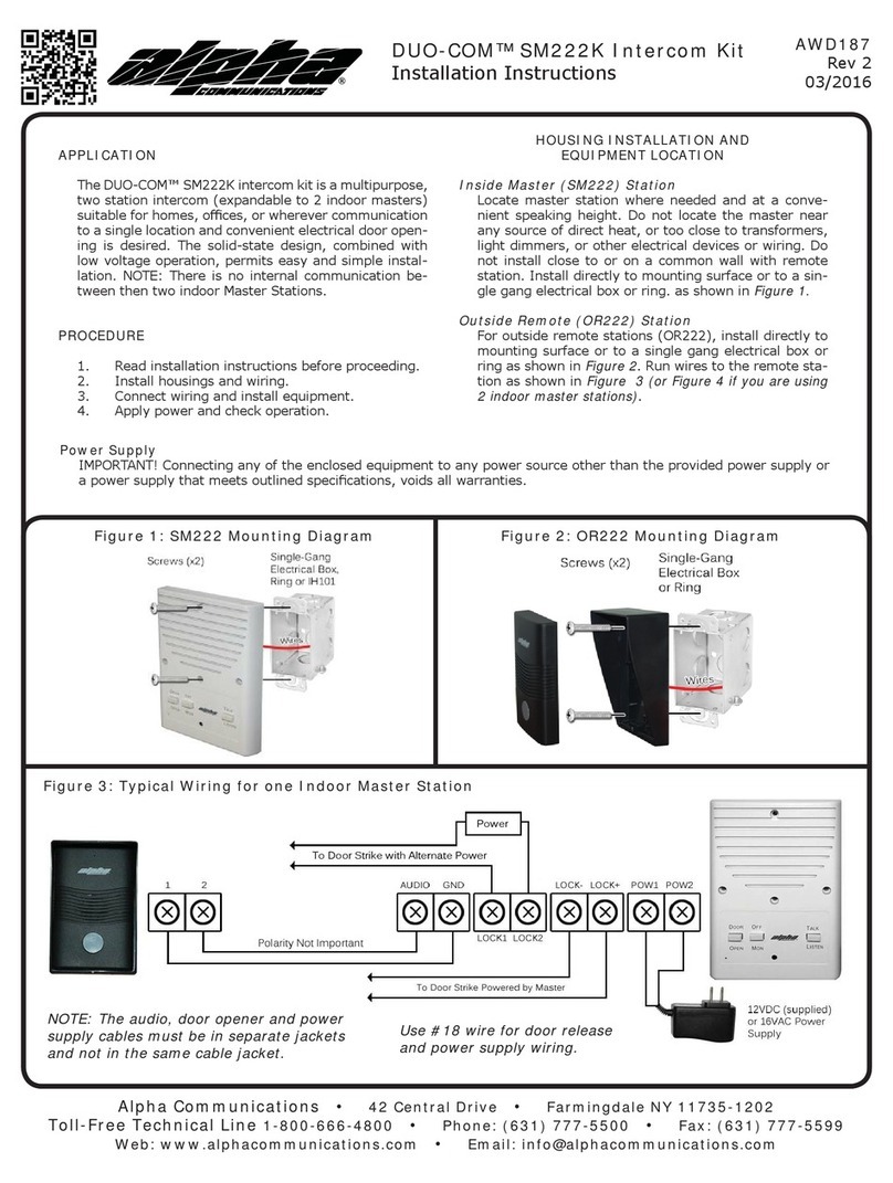
There are two possible variations of this scheme. First, a
closure across PK543 Amplifier’s terminals 1 and E can
be used to output 16 VAC across the amplifier’s terminals
D and K. Second, pressing the DOOR button at a 5-wire
apartment intercom station produces a closure across
the intercom station’s terminals 1 and E (terminal 4).
Door Ajar Indication
This feature is available with the IR104C/LED and
IR204C/LED suite stations. When the door is open and
the door contact is in the closed state, the DOOR button’s
LED will illuminate to indicate the door is ajar.
Post Office Lock
Actuating the post office lock applies closure across the
PK543 Amplifier’s terminals 1 and E (terminal 4). The
PK543Amplifier senses the closure, and outputs 16 VAC
across the amplifier’s terminals D and K. At the same
time, DC voltage is also present across terminals L+ and
L- as the unfiltered output of a full-wave rectifier fed by
the same 16 VAC. This voltage is applied to the door
release to unlock the entrance door.
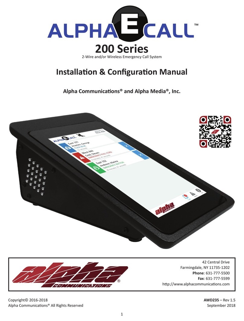
Door
Release
24 VAC #18
24
SS106 Transformer
816
PK543
Add risers
as required
Transformer
Entrance
Panel
Door
Release
117 VAC
2 cond.#18
To additional
suites Suite Station wiring:
3-wire stations: 1 twisted pr #22,
plus 1 cond. 22 gauge per suite
4-wire stations: 1 twisted pr #22
and 1 cond. #22 common, plus 1
cond. 22 gauge per suite. (LED
stations: add an additional 2 #22
conductor to the commons.)
5-wire stations: 2 twisted pr plus 1
cond.#22 per suite
L -
L +
D
K
C
Figure 1—Wiring Layout Diagram Figure 2—Optional Connection for
24 VAC Door Release
Note: Terminal L- is not the same electrically as terminals 1,
G and K.
