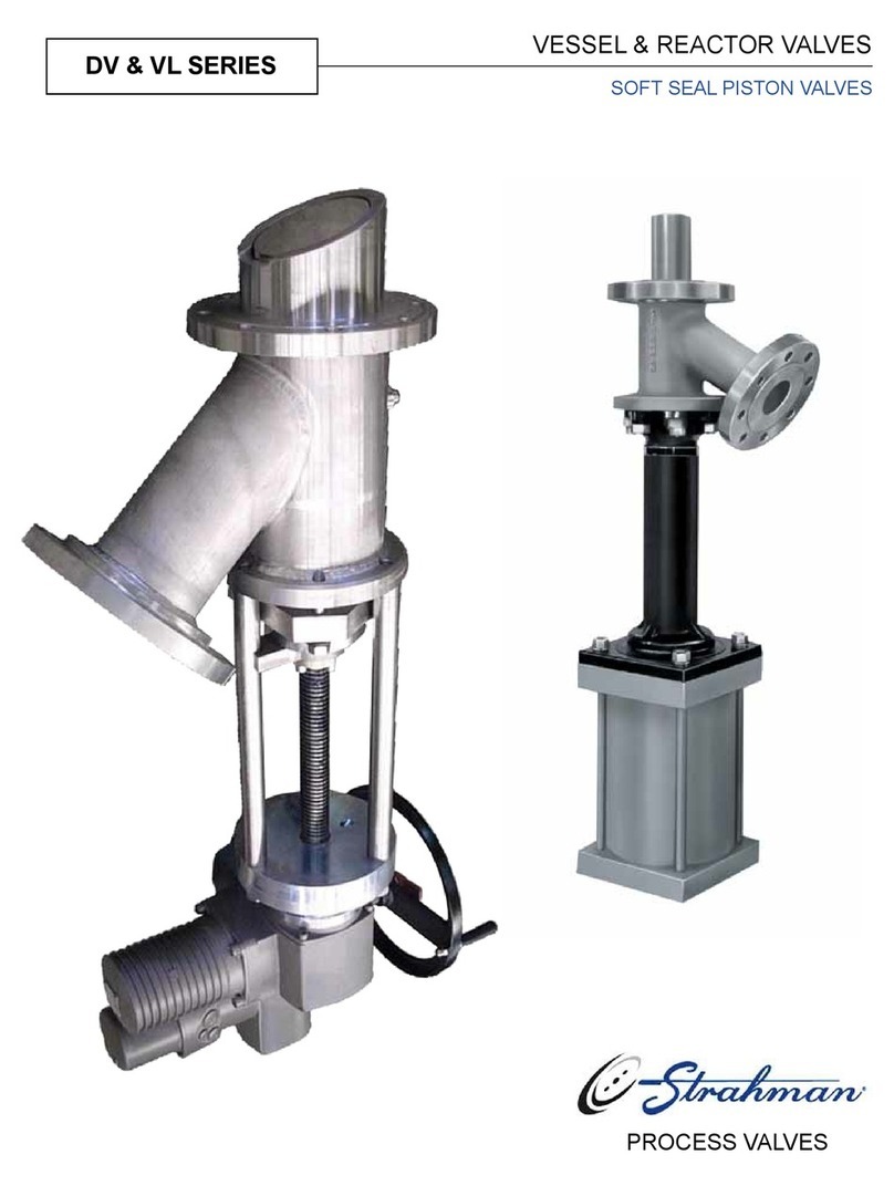
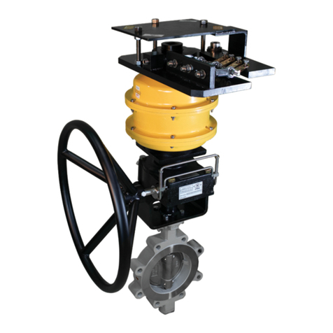
Strahman 740 User manual

Edition le 06/06/06
Révision le 17/07/2014
- 1 -
___________________________________________
LINE BLIND VALVE
INSTRUCTION MANUAL
_____ VALVE TYPE 740,750 AND 760_____
___________________________________________________
____________________ _

Edition le 06/06/06
Révision le 17/07/2014
- 2 -
1–INSTALLATION ............................................................................................. page 3
2–REVERSING THE SPECTACLE PLATE .................................................... page 3
3–LUBRICATION ........................................................................................... page 3
3.1 –Cam lubrication ................................................................................ page 3
4–RECOMMENDED SPARE PARTS ............................................................. page 4
5–MAINTENANCE .............................................................................................. page 4
5.1 –Replacement of the seals with valve installed ................................ page 4
5.1.1 –Seals on body ..................................................................... page 4
5.1.2 - Seals on spectacle plate .................................................... page 4
5.2 –Disassembly of the valve ................................................................. page 4
5.3 –Replacement of stem assembly ........................................................ page 5
5.3.1 –For valve type 750 ............................................................. page 5
5.3.2 - For valve type 740 & 760 .................................................. page 6
6- TABLE 01 & 02 ................................................................................ page 6
7–SCKETCH .............................................................................................. page 7, 8 & 9
8- Additional informations on the actuation of Line Blinds
with groove and tongue .................................................................... page 10

Edition le 06/06/06
Révision le 17/07/2014
- 3 -
1 –INSTALLATION
Good field practice should be observed in the alignment of the connecting piping prior to the installation of the
Fetterolf Line Blind valve.
The “ CAM-SET” mechanism which seals the spectacle plate of the valve is independent of the bolted body
and is unaffected by normal piping loads and strains
Weld end valves should be supported in final position in the pipe line and tack welded.
The final weld between tacks should be made in short passes alternating from one side of the valve to the other.
CAUTION : Protect the surfaces of the spectacle plate from weld spatter.
CAUTION :
Install the Line Blind valve with the « CAM SET » mechanism below the spectacle plate on installations where the pipe
line runs vertically. This will prevent the seal carrier from falling under the force of gravity when the spectacle plate is
rotated.
2 –REVERSING THE SPECTACLE PLATE
CAUTION :
It is not necessary to loosen the body bolts to swing the spectacle plate. The seals in the spectacle plate are readily
inspected and/or replaced prior to swinging the plate.
To release the spectacle plate seals, insert a screwdriver or similar tool trough the handle of the stem (
handwheel if exist) and turn counter clockwise to the limit stop to fully retract the cam-set mechanism.
Rattle the spectacle plate to loosen the seals.
For turning spectacle plate
Pull the plate directly out of the valve body to the limit of travel in the mounting slot and rotate it to line up
with the body.
Push the plate back into the body using care not to damage the seals or mar the sealing surfaces of the spectacle
plate.
For slide spectacle plate
Push or pull the spectacle until the stop.
When correctly positioned, the edge of the plate by turning the stem clockwise until the cam face is drawn up
against the plate and the seal rings are firmly compressed.
The closing torque of stem is indicated in the table 01 according pressure class of the valve and type of seal.
3–LUBRIFICATION
Lubricate periodically the cam set threads, discs, bearing and cams, etc., with Dow Corning “ Molykote Gn” or
equivalent.
The faces of the spectacle plate may be coated with a film of TFE or silicone lubricant to reduce friction.
3.1 –Cam lubrication
For turning spectacle plate

Edition le 06/06/06
Révision le 17/07/2014
- 4 -
Swing the spectacle plate out of the way and maintain it to extract seal carrier, seal and cam.
For slide spectacle plate
Extract completely the spectacle plate by remove the stop Clean et brush cam with grease.
To re-assembly, replace the actuator on the stationary cam with the actuator arm between the stem discs for tye
750. Push the seal carrier down onto the actuator making sure that the inner seal ring is not pinched.
On high temperature applications the parts indicated above should be lubricated each time the plate is swung.
4 - RECOMMENDED SPARE PARTS
It is recommended that a complete set of seals be kept on hand since these parts are the most likely to become damaged.
5 –MAINTENANCE
5.1 - REPLACEMENT OF THE SEALS WITH THE VALVE INSTALLED
5.1.1 –Seal on body
•Retract the CAM SET mechanism by turning the stem fully counter-clockwise.
•Put the turning spectacle plate at 90° or extract completely the slide spectacle plate, see §3.1 Slide the
seal carrier of the end of the body pipe and remove it from the valve.
•Remove the inner pipe seal.
•Pry the primary seals out of the carrier and the body half, using a suitable tool such as a small
screwdriver.
•To install new seal in position , use a non aggressive tool like wood part.
•Install new pipe seal. ( It is interesting to grease cam).
•Install the carrier on the body pipe.
•Swing the spectacle plate into position or replace the slide spectacle plate and close the CAM SET
mechanism to fully seat the seals.
5.1.2 –Seals in spectacle plate
•Seals in the spectacle plate may be replaced in a similar manner by removing the stud holding the plate
and removing it from the assembly for bench replacement of the seals.
5.2 - DISASSEMBLY OF THE VALVE
IF line blind valve is disassemble the guarantee is cancelled.
•Open the valve and remove it from the line if possible.
•Grind off the nut tack welds, remove the top stud, and remove the spectacle plate to prevent damage to the
sealing surfaces.
•Lift off the body half which does not contain the CAM SET mechanism.
•Remove the carrier, pipe and actuator.
•If the stem is to be removed (See REPLACEMENT OF THE STEM ASSEMBLY) Drive out the spring
pins and remove the discs and stem.
•Clean and lubricate all parts.
•Install news seals. (See REPLACEMENT OF THE SEALS)
•Torque the stud nuts as indicated in the table 02 of stud sizes.
•Tack welds all body stud nuts to the studs.

Edition le 06/06/06
Révision le 17/07/2014
- 5 -
5.3 - REPLACEMENT OF THE STEM ASSEMBLY
5.3.1 –For valve type 750
•The replacement stem and actuating disc assemblies have been pre-drilled at the factory and assembled
into sets. Each assembly has been given a letter designation.
•These parts must remain as assemblies so the locating pin holes will be aligned for insertion of pins.
•Clean all metal chips off the stem. Open the valve completely.
•Observe the stem with handwheel on the viewer’s right.
•Mark the stop sleeves, located between the actuating discs and the bearing blocks, with an L& R for left
and right.
•Drive the pins out of the actuating discs.
•Unscrew the stem from the actuating discs and right-hand bearing block.
•Remove the handwheel and key and mount them on the new stem. (if so equipped).
•Thread the stem into the right-hand bearing block.
•Slide the right-hand stop sleeve over the stem. (if so equipped)
•Correctly position the right-hand actuating disc so the lettering is « right side up ».
•Turn the actuating screw until the right-hand disc contacts the actuator arm.
•Position the left-hand actuating disc so the marking reads correctly and screw it onto the stem.
•Slide the left-hand stop sleeve onto the stem.
•Continue to thread the stem through all parts until the pin hole in the right-hand actuating disc lines up
with the hole in the stem and insert a drive pin.
•Align the hole in the left-hand actuating disc and insert a drive pin. The valve handwheel should
tighten the seals prior to the end of stroke.
5.3.2 –For valve type 740 & 760
•Unscrew the yokes.
•Disassembly the stem from the cam.
•Unscrew the stem from the yoke nut.
•Exchange the stem.
•To re-assembly, following this procedure in the opposite way.

Edition le 06/06/06
Révision le 17/07/2014
- 6 -
/ Table 01/
CLOSING TORQUE N.m ( 0.1 m.Kg)
DN
PN 16
PN 64
MM
Inch
Elastomère
PTFE
Elastomère
PTFE
15
½
20
30
23
34
25
1
20
30
23
34
40
1-1/2
20
30
23
34
50
2
27
40
31
46
80
3
34
50
39
58
100
4
40
60
46
69
125
5
88
132
101
151
150
6
115
172
132
198
200
8
170
255
195
292
250
10
204
306
234
351
300
12
240
360
276
414
400
16
310
465
356
534
/ Table 02/
TORQUE in N.m ( 0.1 m.Kg)
Diamètre Boulon
Couple N.m
Inch
Mm
½
12
28
5/8
16
42
¾
20
55
7/8
22
75
1
24
100
1 ¼
32
140
1 ½
36
165
1 1/3
44
295
2
48
610

Edition le 06/06/06
Révision le 17/07/2014
- 7 -
LINE BLIND VALVE TYPE 760

Edition le 06/06/06
Révision le 17/07/2014
- 8 -
LINE BLIND VALVE TYPE 750

Edition le 06/06/06
Révision le 17/07/2014
- 9 -
LINE BLIND VALVE TYPE 740

Edition le 06/06/06
Révision le 17/07/2014
- 10 -
8 -Additional informations on the actuation of Line Blinds with groove and tongue
-loosen the Cam System by means of the handwheel (anti-clockwise turns)
-loosen the seal carrier from the spectacle plate with an appropriate device (steel bar, etc., see photo), on both sides equally
between the « ears » of the seat and the plate
-then bring the plate itsself manually into a neutral position and swing or slide it to the desired position
-afterwards the Cam system can be tightened again with the handwheel (clockwise turns). Thereby check for correct
positioning of tongues in grooves.
This manual suits for next models
2
Table of contents
Other Strahman Control Unit manuals
Popular Control Unit manuals by other brands

Quectel
Quectel SG368Z Series Hardware design

Honeywell
Honeywell ADEMCO 4229 Installation and setup guide

Vertiv
Vertiv NetSure7100 Series Installation and user manual

Dakota Digital
Dakota Digital BIM-13-2 quick start guide
SMC Networks
SMC Networks VP31 5 Series Operation manual

GESTRA
GESTRA NRR 2-2e Installation and service instructions

HEROSE
HEROSE 06810 operating instructions

KSB
KSB Cervomatic EDP.2 operating instructions
esera automation
esera automation 11140 user guide

Pilz
Pilz PNOZ m ES CANopen operating manual
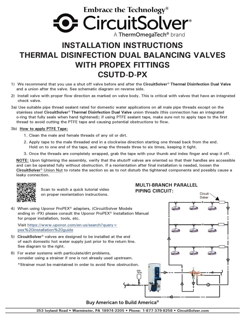
ThermOmegaTech
ThermOmegaTech CircuitSolver CSUTD-D-PX installation instructions
Dantel
Dantel 44093 Installation & operation manual

