Strahman BI-TORQ FL-BT-149 Series User manual

BT SERIES
THERMAL SHUT-OFF VALVES
OPERATIONS AND MAINTENANCE MANUAL
Models FL-BT-149,167X, 157,167, and 187 (Quick Link & DT Gear Version)
WWW.BITORQ.COM Page 1 of 5
3/4/2020
I. OVERVIEW OF THERMAL SHUT-OFF VALVES
BI-TORQ Valve Automation automatic thermal shut-o valves are designed for ow shuto protection in piping systems
handling ammable gasses or liquids, solvents, toxic uids, or any other potentially dangerous media. These re
control valves terminate ow in the event of re, aiding in reducing re intensity. In the event of re, the fusible link
separates, allowing the top mounted spring pack to drive an API607 re safe rated valve into a closed position. Fusible
links are available in a range of temperature settings. The thermal shut-o valves also are available in a fail open
position, ideal for a sprinkler system in the event of a re.
The thermal shut-o valves you have received has been assembled and tested at our factory with attention to safety
in mind. BI-TORQ Valve Automation uses high quality materials and tested engineering to ensure that this product will
operate safely and reliably. Carefully read all instructions before handling in order to avoid injury to the operator or
damage to the product.
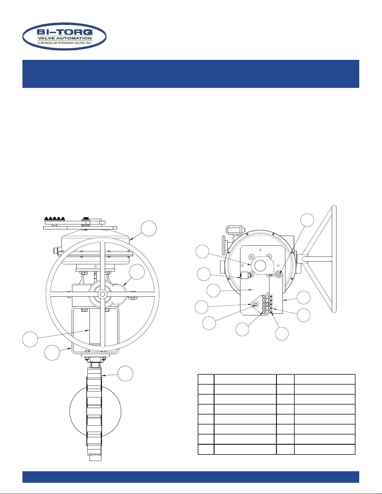
NOTE: Please refer to the attached assembly drawing FL-BT-0600 for parts identication and complete parts list.
II. GENERAL SAFETY INSTRUCTIONS
NOTE: ALL UNITS ARE SHIPPED IN THE CLOSED/SHUT POSITION WITH DECLUTCH GEAR OVERRIDE ENGAGED.
The unit must be installed in a location with carefully maintained ambient temperatures. Installing the link
in locations where high temperature uctuations are possible (such as direct sunlight) is not recommended. Exposure to
high ambient temperatures can cause the fusible links to break prematurely. (See chart 1 for link temperature ratings)
Part Number Yield Temp. Max. Ambient Temp.
314135 135°F/57°F 104°F/41°C
314165 165°F/74°C 135°F/57°C
314212 212°F/100°C 185°F/82°F
314280 280°F/138°C 253°F/123°C
314360 360°F/182°C 330°F/166°C
11
10
8
7
6
9
12
15
14
13
ILLUSTRATION 1.1
all reference numbers
refer to drawing FL-BT-0600
Series Links per assembly
FL-BT-149 8
FL-BT-167X 8
FL-BT-157 10
FL-BT-167 10
FL-BT-189 12
IMAGE OF FUSIBLE LINK

BT SERIES
THERMAL SHUT-OFF VALVES
OPERATIONS AND MAINTENANCE MANUAL
Models FL-BT-149,167X, 157,167, and 187 (Quick Link & DT Gear Version)
WWW.BITORQ.COM Page 2 of 5
3/4/2020
III. ARMING THE BT SERIES ASSEMBLY
NOTE: ALL UNITS ARE SHIPPED IN THE CLOSED/SHUT POSITION WITH DECLUTCH GEAR OVERRIDE ENGAGED.
REQUIRED TOOLS: 9/16” open-ended wrench to install nuts (varies with spring pack) NOTE: INSTALL VALVE IN PIPELINE
BEFORE PROCEEDING!
Note: If you are installing this for the rst time, you will need to attach the handwheel to the declutch gear operator
after installing the assembly in the pipeline.
1. Remove link block (#7) with fusible links attached from the top of the assembly using a 9/16” wrench.
2. Turn the declutch gear handwheel toward the fully open position (CCW) until the handwheel stops. The valve is
now in the open position.
3. Move trigger (#8) toward link block post
4. Place link block over link post and free end of fusible links over link studs on trigger (#8)
5. Add link post screw and washers
6. Rotate handwheel clockwise (CW) approximately 1 to 2 turns until links hold spring tension. NOTE: DO NOT OVER
TIGHTEN AS THIS MAY DAMAGE LINKS
7. Depress declutch lever button and move declutch lever into the disengaged position.
THE LINKS ARE NOW HOLDING THE SPRING AND THE HANDWHEEL WILL SPIN FREELY - THE UNIT IS NOW ARMED.
IV. CLOSING THE ASSEMBLY MANUALLY
1. Depress declutch lever button and move it to the engaged position (movement of handwheel maybe necessary to
mesh internal gears of declutch to do this). NEVER FORCE INTO POSITION.
2. Rotate handwheel counter clockwise(CCW) until it stops.
3. Remove link block (#7) with fusible links attached from the top of the assembly using a 9/16” wrench.
THE VALVE CAN NOW BE SHUT BY TURNING THE HANDWHEEL CLOCKWISE (CW) UNTIL IT STOPS.
REFER TO THE ARMING INSTRUCTIONS ABOVE TO REARM THE ASSEMBLY.
IV. LINK REPLACEMENT
1. Depress declutch lever button and move it to the engaged position (movement of handwheel maybe necessary to
mesh internal gears of declutch to this). NEVER FORCE INTO POSITION.
2. Rotate handwheel counter clockwise(CCW) until it stops.
3. Remove link block (#7) with fusible links attached from the top of the assembly using a 9/16” wrench.
4. Replace links in same conguration as original setup.
5. Finger tighten links to link block (do not over tighten links to block as it may damage them)
6. Place link block over link post and free end of fusible links over link studs on trigger (#8)
7. Add link post screw and washers
REFER TO THE ARMING INSTRUCTIONS ABOVE TO REARM THE ASSEMBLY.

BT SERIES
THERMAL SHUT-OFF VALVES
OPERATIONS AND MAINTENANCE MANUAL
Models FL-BT-149,167X, 157,167, and 187 (Quick Link & DT Gear Version)
WWW.BITORQ.COM Page 3 of 5
3/4/2020
IMPORTANT: THE UNIT IS NOT ARMED UNTIL THE GEAR HAS BEEN PLACED IN THE DISENGAGED POSITION AFTER
INSTALLATION OF LINKS. IF THE GEAR IS LEFT IN THE ENGAGED POSITION THE VALVE WILL NOT SPRING CLOSE.
IV. OPERATION
Once the unit is properly armed, the valve may be operated closed-open in the normal manner using the declutchable
gear handwheel upon removal of the fusible links (reverse “Installation” instructions above). The gear lever must
always be returned to the DISENGAGED position after manually operating the valve and the links must be put back into
place. Failure to return the gear to the disengaged position will lock the gear and valve into position, and the fusible
link assembly will not function properly.
IMPORTANT: THE FUSIBLE LINKS MUST BE RETURNED TO THE ARMED AND INSTALLED POSITION AFTER MANUAL
OPERATION!
VI. OPERATING THE DECLUTCHABLE MANUAL OVERRIDE GEAR
IMPORTANT: MAKE SURE THAT THE FUSIBLE LINKS HAVE BEEN REMOVED BEFORE ATTEMPTING TO OPERATE THE VALVE
WITH THE DECLUTCHABLE MANUAL OVERRIDE.
Use the following instructions to ENGAGE the declutchable manual override.
1. Using one hand, grab the override engagement handle, push in override button and slide the handle in the direction
of the engaged arrow.
2. Once the override handle is in the fully engaged potion, release the override button. The declutch gear override is
now ready to be used. Clockwise rotation of the override handwheel will produce clockwise rotation of the override
output and valve. Conversely, counterclockwise rotation of the handwheel will produce counterclockwise rotation
of the override output, and valve.
Use the following instructions to DISENGAGE the declutchable manual override.
Note: When the assembly is rearmed with the fusible links back in place, the manual override must be returned to
its declutched position. Reversing the procedure above will return the override to the declutched position.
Leaving the declutch engaged will prohibit the spring return unit from cycling the valve to the closed position when the
fusible links yield. Leaving the unit in the engaged position will prevent the unit from operating correctly, may cause
damage to the override as well as drivers linkages, etc. and void the override warranty.
See page 4 for details on declutch.
IMPORTANT: THE FUSIBLE LINKS WILL HAVE TO BE REINSTALLED AND THE
DECLUTCH DISENGAGED BEFORE THE ASSEMBLY IS PROPERLY ARMED.
BT SERIES
THERMAL SHUT-OFF VALVES
OPERATIONS AND MAINTENANCE MANUAL
Models FL-BT-149,167X, 157,167, and 187 (Quick Link & DT Gear Version)
WWW.BITORQ.COM Page 4 of 5
3/4/2020
VI. OPERATING THE DECLUTCHABLE MANUAL OVERRIDE GEAR
IMPORTANT: Make sure that the fusible links have been removed before attempting to operate the valve with the
declutchable manual override.
Use the following instructions to ENGAGE the declutchable manual override.
1. Using one hand, grab the override engagement handle, squeezing the bottom handle and top handle together.
2. With the handles still squeezed together, rotate the handle from its declutched position upward toward the
spring pack mounting ange until the handle locking tabs are inline with their locking positions.
NOTE: In some cases the override gear teeth will not mesh correctly when rotating the handle upward. If this
occurs, rotate the override handwheel slightly to mesh the gears and then rotate the declutch handle upward.
3. Once the override handle is in its locked position, the override is ready to be used. Clockwise rotation of the
override handwheel will produce clockwise rotation of the override output and valve. Conversely,
counterclockwise rotation of the handwheel will produce counterclockwise rotation of the override output,
and valve.
Use the following instructions to DISENGAGE the declutchable manual override.
Note: When the assembly is rearmed with the fusible links back in place, the the manual override must
be returned to its declutched position. Reversing the procedure above will return the override to the declutched
position. Make sure that the handle locking tabs are inserted into their locking position on the override housing.
Leaving the declutch engaged will prohibit the spring return unit from cycling the valve to the closed position when the
fusible links yield. Leaving the unit in the engaged position will prevent the unit from operating correctly, may cause
damage to the override as well as drivers linkages, etc. and void the override warranty.
IMPORTANT: The fusible links will have to be reinstalled and the declutch disengaged before the assembly is properly
armed.
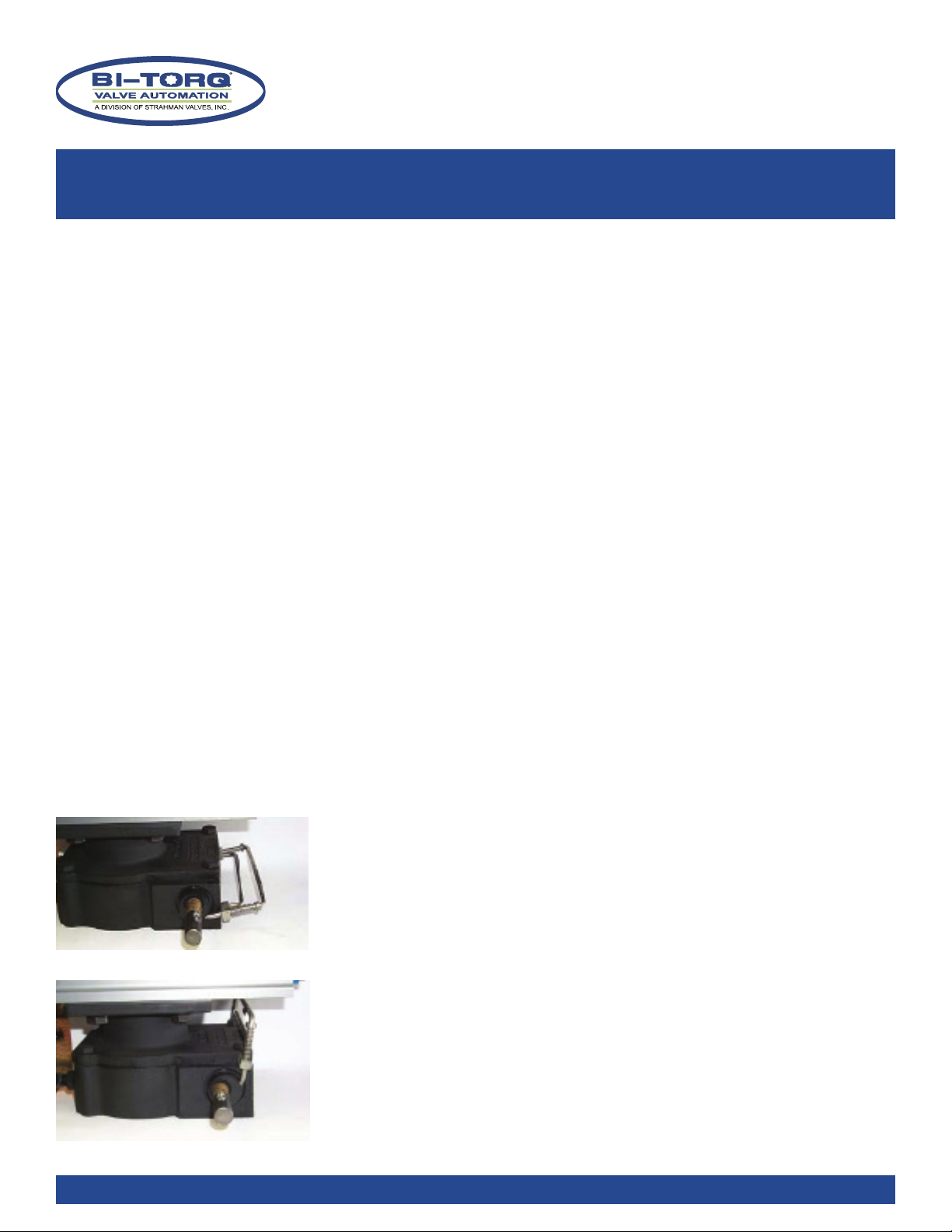
The picture on the left shows the declutch operator in the disengaged to allow
the spring pack to close the valve when the fusible links yield. As shown, the
handle arrangement is pinned in the down position. The handwheel should rotate
freely in either the clockwise or counterclockwise directions without aecting
the valve rotation.
The picture on the left shows the declutch in the “override” position, or
“engaged,” for operating the valve manually. As shown, the handle arrangement
is pinned in the up position for override. Rotation of the hand-wheel clockwise
will rotate valve clockwise (generally closed
direction); rotation of the handwheel counter-clockwise will rotate actuator
counterclockwise (generally open).
IMPORTANT: FUSIBLE LINKS MUST BE REMOVED BEFORE ATTEMPTING TO OPERATE
THE VALVE WITH THE DECLUTCH.
DISENGAGED
ENGAGED
BT SERIES
THERMAL SHUT-OFF VALVES
OPERATIONS AND MAINTENANCE MANUAL
Models FL-BT-149,167X, 157,167, and 187 (Quick Link & DT Gear Version)
WWW.BITORQ.COM Page 5 of 5
3/4/2020
V. MAINTENANCE
IMPORTANT: The fusible link manufacturer recommends annual replacement of link(s) as part of a regular maintenance
schedule. Contact your local distributor or BI-TORQ Valve Automation for replacement links. Order by part number or
temperature rating on old link. Replacement valve seats and seals subject to normal wear are available from your local
distributor or BI-TORQ Valve Automation. The spring case and declutchable gear are lifetime lubricated and do not
require maintenance. Disassembly of the spring case or gear will void any written or verbal warranties.
WARNING: THE SPRING CASE CLOCKSPRING IS ALWAYS UNDER PRESSURE. DO NOT DISASSEMBLE SPRING PACK UNDER ANY
CIRCUMSTANCES. DISASSEMBLY OF THE SPRING PACK COULD RESULT IN SERIOUS INJURY OR DEATH.
IMPORTANT: IMPROPER INSTALLATION OR ARMING OF FUSIBLE LINK ASSEMBLIES WILL VOID WARRANTY, AS WILL
DISASSEMBLY OF THE PRODUCT WITHOUT PRIOR APPROVAL FROM FACTORY.
ASSEMBLY DRAWING FL-BT-0600
1 1/4 turn valve 9 arming plate
2 mounting bracket 10 tripper
3declutch coupler 11 stop
4 declutch gear 12 shoulder bolt
5 spring pack 13 link post
6 fusible links 14 link retaining bolts
7 link block 15 link studs
8 trigger 16 cover plate
PARTS LIST
1
2
3
4
5
11
10
8
7
6
9
12
15
14
13
Shown without
cover plate (#16)
for clarity
This manual suits for next models
4
Table of contents
Other Strahman Control Unit manuals


Popular Control Unit manuals by other brands


Emerson
Emerson Anderson Greenwood 93 Series Installation and maintenance instructions

Cooper Menvier
Cooper Menvier Scantronic 9651 user guide

Arduino
Arduino MKR1000 Getting started

Honeywell
Honeywell TR80UWD Installation and operating guide

BFT
BFT ALPHA BOM Installation and user manual

Aprilaire
Aprilaire 76 installation instructions


