manuals.online logo
Brands
  1. Home
  2. •
  3. Brands
  4. •
  5. DSC
  6. •
  7. Control Unit
  8. •
  9. DSC PowerSeries User manual

DSC PowerSeries User manual

Product Summary Sheet July 7, 2003 Rev001
Escort5580(TC) – PowerSeries Telephone Interface & Automation Control Module
Troubleshooting:
1. If a busy tone is heard when the Telephone Access Code is
entered, it may because the [*] key is conflicting with a service
offered by the phone company. Download a new Telephone
Access Code.
2. Phones that only generate short tones may not work. The tone
generated for each key press must be minimum 200 mS.
3. For the Escort v1.x to answer remotely downloading must be
enabled in the control panel – Section [401], option [1] ON.
4. The Escort may have difficulty hearing tones if called remotely
from a different line in the same building because of cross-talk
on the lines. Try calling from a cell phone or an actual remote
location.
Compatibility (Version Identification):
The version of the Escort is printed on a sticker affixed to the main
chip.
Version 1.0 Original release
Version 1.1 Support for user code programming
Version 1.2 Support for different languages
Version 1.2TA v1.2 with French voice
Version 1.2TF v1.2 with Spanish voice
Version 2.0 Support for thermostat control
Version 2.02 Changed F, A and P key operation
Version 3.0 Support for Power864, 64 zones, 8 partitions,
audio port added to allow for verbal door chime
and verbal alarm (requires PC5936 module)
Wiring:
KEYBUS Connect RED, BLK, YEL and GRN terminals to the
KEYBUS terminals on the main control panel
TIP, RING Connect to T1, R1 of the main control panel
T1, R1 Connect to house phones
Receiving Incoming Calls:
If an incoming call is detected while the Escort is being accessed it
will announce:
Attention. You have an incoming call. To receive call, press [#]
now.
Press [#] and the Escort will connect the user to the incoming call.
Accessing the Escort:
Local Access:
1. Pick up a local telephone handset.
2. Enter the Telephone Access Code. Default is [*][*][*].
3. If an access code is required the Escort will announce ‘Enter
your access code’ – Section [021], Option [02].
4. The Escort will announce ‘Hello’ and begin to announce the
status of the system.
Remote Access:
1. Turn on remote access – Section [021], option [01] ON.
2. Call the Escort. Let the phone ring one full ring, hang up and
call again.
3. The Escort will announce ‘Hello’.
4. Enter the Telephone Access Code. Default is [*][*][*].
5. The Escort will announce ‘Enter your access code’.
6. Enter a valid access code.
7. The Escort will begin to announce the status of the system.
8. If the Telephone Access Code is not entered, or an invalid user
code is entered, the Escort will announce ‘Goodbye’ and hang
up.
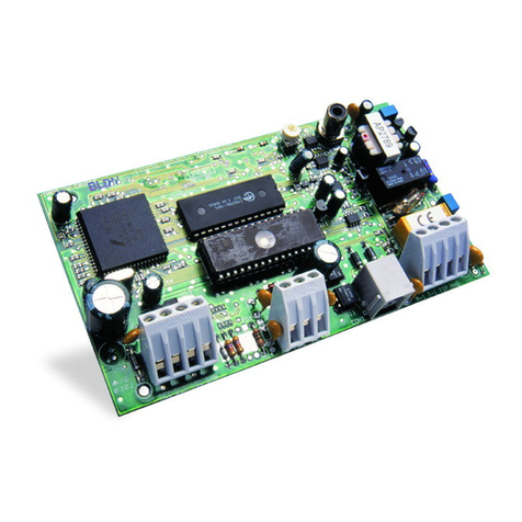
The Escort5580(TC) module is a telephone interface module that turns any tone phone, local or remote, into a fully functional keypad. The
Escort5580(TC) uses full sentence prompts to simplify operation. The module also includes an X-10 interface jack and can be used to support up
to 32 X-10 devices with the addition of a PSC04 X-10 interface module.
The ‘TC’ designator in the part number indicates the unit also includes thermostat control. Up to 4 thermostats can be controlled.
The module contains an extensive 240+ word library. Up to 6 words can be programmed for all labels (zones, partitions, X-10 automation items)
to simplify operation for the end user. Programming the Escort module is done using any local tone telephone or downloading.

Power 832 Application Notes – ESCORT Module Labels
Operation: The ESCORT module has programmable labels for zones, Partitions, keypad functions
etc… Up to 6 words from the library can be programmed for each, including the ability
to say any number between 0 and 999 three different ways.
Applications:
1. Programmed labels make the system easier to use. Rather than reading an abbreviated LCD label or
referring to a handwritten door label, the ESCORT will clearly announce the zone label.
example – ‘upstairs master bedroom window contact’
Program Sections: ESCORT Section [451] to [482] – Automation Item Labels
ESCORT Section [521] to [528] – Automation Mode Labels
ESCORT Section [545] to [546] – Miscellaneous System Labels
ESCORT Section [561] to [562] – System Partition Labels
ESCORT Section [601] to [633] – System Zone Labels
Label Library - Words
The word library is located in Appendix A of the ESCORT Installation manual and contains approximately
240 words. A three-digit number is assigned to each word. From the list, write down the three-digit
numbers for each word required for each label.
For example – ‘Living Room Motion Detector’ [127] = Living
[183] = Room
[145] = Motion
[054] = Detector
Label Library – Numbers
The ESCORT has the ability to say any number from 0 to 999 three different ways, Combined, Ordered
and Individual. Two of the six programmable words for a label are required to say a number, the first word
is how you want the number stated, the second is the actual number itself.
The following is an example of how the ESCORT can say the number (401).
Combined =‘Four Hundred and One’
Ordered =‘Four Hundred and First’
Individual =‘Four Zero One’
example – ‘Second Floor Bedroom Smoke Detector’ [001] = Ordered
[002] = the number 2 (announced as ‘Second’)
[079] = Floor
[023] = Bedroom
[197] = Smoke
[054] = Detector
Procedure:
To enter ESCORT programming, perform the following on any local touch tone phone:
-Enter [*] [*] [*] on any local touch tone phone to turn the ESCORT on
-Enter [*] [8] [ESCORT Service Code] – default is [5580]
For information regarding how the ESCORT is programmed, please refer to the ESCORT 5580 Installation
Manual.
Step 1 – Automation Item Labels – ESCORT Section [451] to [482]
NOTE – This step is only required if the ESCORT is being used for Automation control.
Enter the correct Section and enter the three-digit numbers for the label. If all 6 words are used, the
ESCORT will announce the new label after the last three-digit word is entered, then will exit the Section.
If all 6 words are not used, press the [#] to exit the Section and the ESCORT will announce the new label.
Step 2 – Automation Mode Labels – ESCORT Section [521] to [528]
NOTE – This step is only required if the ESCORT is being used for Automation control.
Enter the correct Section and enter the three-digit numbers for the label. If all 6 words are used, the
ESCORT will announce the new label after the last three-digit word is entered, then will exit the Section.
If all 6 words are not used, press the [#] to exit the Section and the ESCORT will announce the new label.
Step 3 – Miscellaneous System Labels – ESCORT Section [545] to [546]
Enter the correct Section and enter the three-digit numbers for the label. If all 6 words are used, the
ESCORT will announce the new label after the last three-digit word is entered, then will exit the Section.
If all 6 words are not used, press the [#] to exit the Section and the ESCORT will announce the new label.
Step 4 – System Partition Labels – ESCORT Section [561] to [562]
Enter the correct Section and enter the three-digit numbers for the label. If all 6 words are used, the
ESCORT will announce the new label after the last three-digit word is entered, then will exit the Section.
If all 6 words are not used, press the [#] to exit the Section and the ESCORT will announce the new label.
Step 5 – System Zone Labels – ESCORT Section [601] to [633]
Enter the correct Section and enter the three-digit numbers for the label. If all 6 words are used, the
ESCORT will announce the new label after the last three-digit word is entered, then will exit the Section.
If all 6 words are not used, press the [#] to exit the Section and the ESCORT will announce the new label.
NOTE – The last System zone label, Section [633], is for PGM2 if it is being used for two-wire smoke
detectors.
Escort5580TC and EMS-100 – Setting Temperatures
Application: This application will describe how the user can select the temperature set points for the
different Occupancy Settings (Day Setting, Night Setting, Away Setting and Aux
Setting), using a touch tone telephone, the LCD keypad or the EMS-100 thermostat.
Equipment:
-Power 832 v2.x or greater
-LCD5500 v2.1 or greater (optional)
-Escort5580TC Module
-EMS-100 Thermostat
-EMS-ITS Internal Temperature Sensor (optional)
-EMS-OTS Outdoor Temperature Sensor (optional)
Special Notes:
1. The Application Note assumes that the EMS-100 will be used to control both heating and cooling.
2. The user cannot ‘temporarily’ change the temperature. Any time the user manually changes the
temperature set point for an Occupancy Setting, it will change to the new setting.
Program Sections: None
Programming the Temperature Set Points for an Occupancy Setting via the EMS-100
The EMS-100 uses symbols to display the present Occupancy Setting (Day = sun, Night = moon; Away =
house and cloud, AUX = house only). The [Day/Night] key will allow the user to toggle between Day and
Night Occupancy Settings or Away and Aux Settings.
Note - The [Day/Night] key on the EMS-100 is limited to changing between two Occupancy settings
only (Day/Night or Away/Aux). If the unit is in Day or Night Occupancy Setting, the [Day/Night]
key will toggle between the two. If the EMS-100 is in Aux or Away Occupancy Setting, the
[Day/Night] key will toggle between the two.
The Escort and LCD keypad allow you to change between all four Occupancy Settings. To set the heating
and cooling temperatures for a Setting, perform the following functions on the EMS-100:
1. Press the [Day/Night] key and ensure the unit the correct Occupancy Setting is displayed.
2. Press the [Setting] key until the word COOL is displayed (small snowflake).
3. Use the [Up]/[Down] arrows to set the temperature that cooling should begin.
4. Press the [Setting] key until the word HEAT appears (small flame).
5. Use the [Up]/[Down] arrow keys to set the temperature that heating should begin.
6. Press the [Setting] key until the word AUTO appears (small snowflake and small flame).
Programming the Temperature Set Points for an Occupancy Setting via the LCD Keypad
Press [*] to bring up the user command menu.
Step 1 – Scroll to ‘Thermostat Ctrl’ then press the [*] key to select the option.
Step 2 – Scroll to the correct Thermostat (1 through 4) then press the [*] key to select the option.
Step 3 – Scroll to ‘Occupancy Mode’ then press the [*] key to select the option.
Step 4 – Scroll through the 4 different Occupancy Settings (the Occupancy Setting the EMS-100 is in will
appear with a [*] beside it. When the desired Occupancy Setting is displayed, press the [*] key to
select it.
Step 5 – Scroll to ‘Setting Temp.’ then press the [*] key to select the option.
Step 6 – Scroll to ‘Heat Temp.’ then press the [*] key to select the option.
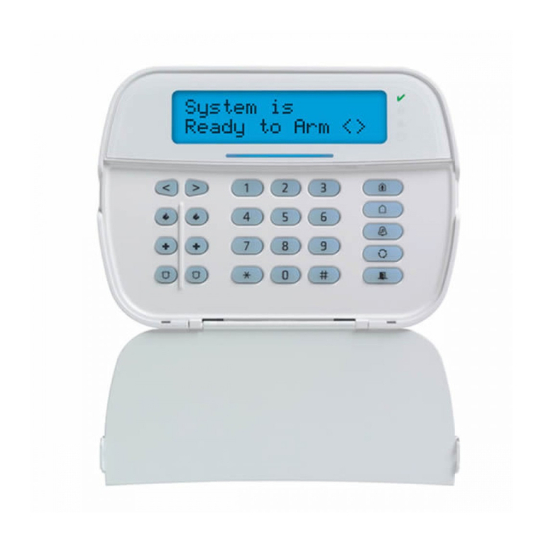
Step 7 – The keypad will display the following:
Use the arrow keys (< >) to select the desired temperature
then press the [*] key to save and exit.
Step 8 – Scroll to ‘Cool Temp.’ then press the [*] key to select the option.
Step 9 – The keypad will display the following:
Use the arrow keys (< >) to select the desired temperature
then press the [*] key to save and exit.
Continue these steps to set the temperature set points for the other Occupancy Settings being used in the
installation.
Programming the Temperature Set Points for an Occupancy Setting using the Escort
On any local, touch tone telephone, enter the Local/Remote Access Code - [*] [*] [*]
Step 1 – Press [*] [5] [2] for Temperature Control
Escort will announce:‘For Individual Thermostat Control, press [1]’
Step 2 – Press [1] for Thermostat Control
Escort will announce:‘Thermostat XX’
‘Interior Temperature is XX degrees’
‘Exterior Temperature is XX degrees’
‘The Occupancy Setting is Auxiliary/Day/Away/Night’
‘The Fan is On/Automatic’
‘To set Temperature, press [1]’
‘For Occupancy Setting, press [2]’
‘For Thermostat Setting, press [3]
‘For Fan Control, press [4]’
Temp. is 72
°
< >
68° Heat
Temp. is 72
°
< >
74° Cool
Step 3 – Press [2] for Occupancy Setting Setting
The Escort will announce the present Occupancy Setting. Press the [1] key until the desired Occupancy
Setting is announced, then press the [#] key to save and exit.
Step 4 – Press [1] to Set the Temperature
The Escort will announce: ‘Cool Temperature is XX Degrees’
‘Heat Temperature is XX Degrees’
‘To change Cool Temperature, press [1]’
‘To change Heat Temperature, press [2]’
Step 5 – Press [1] to Set the Cool Temperature
The Escort will ask you to enter a two-digit number for the new Cool Temperature set point. After it is
entered, the Escort will read back the new temperature set point.
Step 6 – Press [2] to Set the Heat Temperature
The Escort will ask you to enter a two-digit number for the new Heat Temperature set point. After it is
entered, the Escort will read back the new temperature set point.
Continue these steps to program the temperature set points for all the different Occupancy Settings being
used.
Escort5580TC and EMS-100 – Thermostat Output Control
Application: This application will provide an example for setting the temperature depending on the
armed status of the panel. The Escort will change the temperature to the programmed
setting when the panel is armed in the Stay or Away setting, or when disarmed.
Equipment:
-Power 832 v2.x or greater
-LCD5500 v2.1 or greater (optional)
-Escort5580TC Module
-EMS-100 Thermostat
-EMS-ITS Internal Temperature Sensor (optional)
-EMS-OTS Outdoor Temperature Sensor (optional)
Special Notes:
1. The Application Note assumes that the EMS-100 will be used to control both heating and cooling.
2. The user cannot ‘temporarily’ change the temperature. Any time the user manually changes the
temperature set point for an Occupancy Setting, it will change to the new setting.
Program Sections: Escort Section [800] - Thermostat 1 Options
Escort Section [803] - Thermostat 1 Day Setting Output Option
Escort Section [804] - Thermostat 1 Day Setting PGM Output
Escort Section [808] - Thermostat 1 Night Setting Output Option
Escort Section [809] - Thermostat 1 Night Setting PGM Output
Escort Section [818] - Thermostat 1 Away Setting Output Option
Escort Section [819] - Thermostat 1 Away Setting PGM Output
Panel Section [010], [143] - PC5208 PGM Output Programming
Procedure:
For information regarding how the Escort is programmed, please refer to the Escort5580TC Installation
Manual.
Step 1 – Thermostat 1 Options – Escort Section [800]
•Turn Option [01] ON to enable the thermostat.
•Turn Option [02] ON if an EMS-OTS outdoor temperature sensor is connected.
•Turn Option [03] ON if the thermostat will be used to control heating.
•Turn Option [04] ON if the thermostat will be used to control cooling.
•Turn Option [05] ON so the Day Occupancy Setting will always activate by output control.
•Turn Option [06] ON so the Night Occupancy Setting will always activate by output control.
•Turn Option [07] OFF as the Aux Occupancy Setting will not be used.
•Turn Option [08] ON so the Away Occupancy Setting will always activate by output control.
Step 2 – Thermostat 1 Day Occupancy Setting Output Option – Escort Section [803]
Program data [01] for output control only. The user will always have manual control as well.
Step 3 - Thermostat 1 Day Occupancy Setting PGM Output – Escort Section [804]
Program data [03]. The Escort will adjust the temperature to the value programmed for the Day Occupancy
Setting when PGM Output [03] is activated by the panel.
Step 4 – Thermostat 1 Night Occupancy Setting Output Option – Escort Section [808]
Program data [01] for output control only. The user will always have manual control as well.
Step 5 - Thermostat 1 Night Occupancy Setting PGM Output – Escort Section [809]
Program data [05]. The Escort will adjust the temperature to the value programmed for the Night
Occupancy Setting when PGM Output [05] is activated by the panel.
Step 6 – Thermostat 1 Away Occupancy Setting Output Option – Escort Section [818]
Program data [01] for output control only. The user will always have manual control as well.
Step 7 - Thermostat 1 Away Occupancy Setting PGM Output – Escort Section [819]
Program data [04]. The Escort will adjust the temperature to the value programmed for the Away
Occupancy Setting when PGM Output [04] is activated by the panel.
Step 8 – PGM Output 03 to 10 Programming – Panel Section [010], [143]
Three different outputs are needed; stay arm, away arm and disarm. To get an output to activate for disarm
status, we must ‘invert’ an output programmed for armed status.
Section [010] - Program the following:
PGM 03 data [05] data [05] for ‘Armed Status’
PGM 04 data [17] data [17] for ‘Away Arm’
PGM 05 data [18] data [18] for ‘Stay Arm’
Section [143] – Program the following:
Turn Option [1] ON enable partition 1
Turn Option [2] ON enable partition 2
Turn Option [3] OFF will ‘invert’ the output – instead of activating when
the panel is armed, the output will activate when the
panel is disarmed.
Operation: When the panel is armed in the ‘stay’ setting, the panel will activate PGM Output [05]
and the Escort will adjust the temperature to the value programmed for the Night
Occupancy Setting. When the panel is armed in the away setting, the panel will activate
PGM Output [04] and the Escort will adjust the temperature to the value programmed for
the Away Occupancy Setting. When the panel is disarmed, the panel will activate PGM
Output [03], and the Escort will adjust the temperature to the value programmed for the
Day Occupancy Setting.
Escort5580TC and EMS-100 - Thermostat Scheduling Control
Application: Typical home installation with one thermostat. This application will provide an example
for setting the temperature by schedule. The Escort will automatically change the
temperature to the programmed setting at 8:00 am and 11:00 pm.
Equipment:
-Power 832 v2.x or greater
-LCD5500 v2.1 or greater (optional)
-Escort5580TC Module
-EMS-100 Thermostat
-EMS-ITS Internal Temperature Sensor (optional)
-EMS-OTS Outdoor Temperature Sensor (optional)
Special Notes:
1. The Application Note assumes that the EMS-100 will be used to control both heating and cooling.
2. The user cannot ‘temporarily’ change the temperature. Any time the user manually changes the
temperature set point for an Occupancy Setting, it will change to the new setting.
Program Sections: Escort Section [030] to [032] - Schedule [01] Programming
Escort Section [033] to [035] - Schedule [02] Programming
Escort Section [800] - Thermostat 1 Options
Escort Section [801] - Thermostat 1 Day Setting Schedules
Escort Section [803] - Thermostat 1 Day Setting Output Option
Escort Section [806] - Thermostat 1 Night Setting Schedules
Escort Section [808] - Thermostat 1 Night Setting Output Option
Procedure:
For information regarding how the Escort is programmed, please refer to the Escort5580TC Installation
Manual.
Step 1 – Schedule [01] Programming – Escort Section [030] to [032]
Each of the 16 schedules contain three program items; On time, Off Time and Day of the Week selection.
The new temperature will be set when the schedule is activated (On Time) so no Off Time is required.
Schedule [01] will be used for the Day Occupancy Setting (starting at 8:00 am) and will be programmed as
follows:
•Program data [0800] in Section [030] (8:00 am On Time)
•Program data [9999] in Section [031] (no Off Time is required)
•Turn Options [01] through [07] ON in Section [032] to enable all days of the week.
Step 2 – Schedule [02] Programming – Escort Section [033] to [035]
Schedule [02] will be used for the Night Occupancy Setting (starting at 11:00 pm) and will be programmed
as follows:
•Program data [2300] in Section [033] (11:00 pm On Time)
•Program data [9999] in Section [034] (no Off Time is required)
•Turn Options [01] through [07] ON in Section [035] to enable all days of the week.
Step 3 – Thermostat 1 Options – Escort Section [800]
•Turn Option [01] ON to enable the thermostat.
•Turn Option [02] ON if an EMS-OTS outdoor temperature sensor is connected.
•Turn Option [03] ON if the thermostat will be used to control heating.
•Turn Option [04] ON if the thermostat will be used to control cooling.
•Turn Option [05] ON so the Day Occupancy Setting will always activate by schedule.
•Turn Option [06] ON so the Night Occupancy Setting will always activate by schedule.
•Turn Option [07] and [08] OFF as the Away and Auxiliary Occupancy Settings are not being used.
Step 4 – Thermostat 1 Day Occupancy Setting Schedule Assignment – Escort Section [801]
Turn Option [01] ON for the Day Occupancy Setting to follow Schedule [01].
Step 5 – Thermostat 1 Day Occupancy Setting Output Option – Escort Section [803]
Program data [02] for schedule control only. The user will always have manual control as well.
Step 6 – Thermostat 1 Night Occupancy Setting Schedule Assignment – Escort Section [806]
Turn Option [02] ON for the Night Occupancy Setting to follow Schedule [02].
Step 7 – Thermostat 1 Night Occupancy Setting Output Option – Escort Section [808]
Program data [02] for schedule control only. The user will always have manual control as well.
Operation: At 8:00 am, every day, the Escort will adjust the temperature to the value programmed
for theDay Occupancy Setting and at 11:00 pm the Escort will adjust the temperature to the value
programmed for the Night Occupancy Setting.
Power 832 Application Notes – ESCORT Module
Operation: The PC5580 ESCORT module will turn any touch tone telephone, either local or remote,
into a fully functional keypad.
Applications:
1. Reduce the number of keypads required for a system.
2. ESCORT talks in clear, easy to understand sentences. Helps to guide a user through all functions and
features and will provide ‘talking’ confirmation of key presses.
3. Allows a user to check the status of the system, as well as arm and disarm for maintenance people
while on vacation or at the office.
Special Notes:
1. All ESCORT programming is done through an on-site touch tone telephone or via the downloading
software.
2. To program labels into the ESCORT, refer to Application Notes – ESCORT Module Labels.
3. If a phone line trouble is present, the ESCORT will provide a 20 mA loop current so that the system
can still be accessed through a local phone.
Program Sections: ESCORT Section [001] – Service Code
ESCORT Section [002] – First System Options
ESCORT Section [003] – Status Prompt Mask
ESCORT Section [004] – Star Function Prompt Mask
ESCORT Section [005] to [006] – Local Programming Lockout
ESCORT Section [020] – Local/Remote Phone Access Code
ESCORT Section [021] – Phone Access Options
Procedure:
To enter ESCORT programming, perform the following on any local touch tone phone:
-Enter [*] [*] [*] on any local touch tone phone to turn the ESCORT on
-Enter [*] [8] [ESCORT Service Code] – default is [5580]
For information regarding how the ESCORT is programmed, please refer to the ESCORT 5580 Installation
Manual.
Step 1 – Service Code – ESCORT Section [000]
Enter a new 4 digit ESCORT Service Code.
Step 2 – First System Options – ESCORT Section [001]
This Section is used to select which Partitions can be accessed. To allow the user to access Partition 1, turn
Option [1] ON. To allow the user to access Partition 2, turn Option [2] ON.
Step 3 – Status Prompt Mask – ESCORT Section [002]
Certain messages can be deleted from the ESCORT to help reduce confusion to the end user. Turn the
corresponding Option OFF to disable unwanted messages.
Step 4 – Star Function Prompt Mask – ESCORT Section [003]
Certain [*] function messages can be deleted from the ESCORT if they are not applicable to the
installation. For example, if auto arming is not being used, deleting these messages can help reduce
confusion and unwanted questions. Turn the corresponding Option OFF to disable unwanted messages.
Step 5 – Local Programming Lockout – ESCORT Section [005] to [006]
The ESCORT can be programmed to ‘lockout’ after an incorrect number of Service Codes are entered.
Program the number of incorrect Service Codes required to cause ‘lockout’ in Section [005] and the
number of minutes for the ‘lockout’ duration in Section [006]. While in ‘lockout’ the ESCORT will not
allow local programming, even if the correct Service Code is entered.
Step 6 – Local/Remote Phone Access Code – ESCORT Section [020]
Certain answering machines use the [*] key as a function key and may interfere with the [*] [*] [*]
command required to turn the ESCORT on. Reprogram the Local/Remote Access Code if this is the case.
Ensure that at least one [*] or [#] is in the code.
Step 7 – Phone Access Options – ESCORT Section [021]
This Section is used to determine access to the ESCORT. If only local access is required, turn Option [1]
ON. If both local and remote access is required, turn Option [1] OFF.
A valid access code is always required to access the ESCORT remotely. If you want an access code to be
required to access the ESCORT locally, or if the system has two Partitions and you need access to both via
the ESCORT, turn Option [2] ON. If the system has one Partition and an access code is not required for
local access, turn Option [2] OFF.
Power 832 Application Notes – X-10 Automation (Schedule Control)
Application: The ESCORT can be used to control up to 32 X-10 automation devices. This Application
Note will cover the basic programming required for scheduling light control, specifically
to turn a light on at 8:00 am and off at 8:00 pm, every day of the week. Additional
Application Notes are available for output and manual control.
Equipment:
-Power 832 control panel
-ESCORT 5580 module
-X-10 controller (PL-513 or PSC-04)
-X-10 light module
Special Notes:
Program Sections: ESCORT Section [002] - First System Options
ESCORT Section [007] - Number of Automation Transmissions
ESCORT Section [130] - Item #01 House Code & Unit Number
ESCORT Section [131] - Item #01 Miscellaneous Options
ESCORT Section [132] - Item #01 Schedule Assignment
ESCORT Section [134] - Item #01 Schedule/Output Condition
ESCORT Section [030] to [032] - Schedule #01 Programming
Procedure:
To enter ESCORT programming, perform the following on any local touch tone phone:
-Enter [*] [*] [*] on any local touch tone phone to turn the ESCORT on
-Enter [*] [8] [ESCORT Service Code] – default is [5580]
For information regarding how the ESCORT is programmed, please refer to the ESCORT 5580 Installation
Manual.
Step 1 – First System Options – ESCORT Section [002]
•Turn Option [03] ON to enable Home Automation.
•An access can be required to enter the [*] [5] Automation for additional security. If Option [04] is ON,
an access code is required. If Option [04] is OFF, an access code is not required.
Step 2 – Number of Automation Transmissions – ESCORT Section [007]
The number of Automation transmissions can be changed to increase reliability. Since the Automation
transmissions are non-confirmed and occur over the existing AC wiring of the premises, having the
ESCORT transmit multiple On/Off commands can increase reliability.
•Program the number of on/off transmissions to be sent for each command.
•Note, each transmission takes approximately one second. The larger the number, the slower the
Automation system will appear to operate.
Step 3 – Item #01 House Code & Unit Number – ESCORT Section [130]
Each light module has dials for selecting a unique address for each. A unique address is required for each
light module so that the user can control them individually. One dial is used to select from letter [A] to [P],
the other dial is used to select a number from [1] to [16].
•Referring to Appendix B, program the three digit code equivalent to the letter and number
corresponding to the letter and number selected for the first X-10 light module (i.e. [A1] = [000]).
Step 4 – Item #01 Miscellaneous Options – ESCORT Section [131]
•Turn Option [01] ON to enable the X-10 module.
•Turn Option [02] ON to enable end user manual control.
Option [03] allows you to select if the X-10 module will be included in global commands. For example,
several light modules may present to control downstairs lighting. At bedtime, rather than having to turn off
each light module individually, the user could initiate a ‘global off’ command. All the light modules
included in the global command option would be turned off.
•Turn Option [03] ON to include the X-10 module in the global command group. Turn Option [03]
OFF to exclude the X-10 module from the global command group.
•Turn Option [04] ON to enable dimming.
•Turn Option [05] ON so that the light module will always turn on or off when scheduled to do so.
•Turn Option [06] ON so that the light will remain on until told to turn off.
The Escort can be programmed to announce different words when an X-10 module is activated/deactivated.
Depending on the application, turn Option [07], [08] or [09] ON. Only turn ON one of these options. In
the case of lighting, it is logical for the Escort to announce ‘on’ and ‘off’.
•Turn Option [07] ON so that the ESCORT will announce the light is on and off when activated.
•Turn Option [08] OFF.
•Turn Option [09] OFF.
Step 5 – Item #01 Schedule Assignment – ESCORT Section [132]
Each X-10 module can be programmed to follow any or all of the 16 available schedules. In our
application, only one schedule is required.
•Turn Option [01] to enable Schedule #01.
Step 6 – Item #01 Schedule/Output Condition – ESCORT Section [134]
•Enter data [02] to enable schedule control.
Step 7 – ESCORT Schedule #01 Programming – ESCORT Section [030] to [032]
Each of the 16 schedules contain three program items; On time, Off Time and Day of the Week selection.
•Program data [0800] in Section [030] (8:00 am On Time)
•Program data [2000] in Section [031] (8:00 pm Off Time)
•Turn Options [01] through [07] ON to enable all days of the week.
Step 8 – Program Additional X-10 Modules
Repeat steps 3 through 7 for each X-10 module on the system. The programming is identical, however the
Section numbers are different for each.
Summary:
The user will be able to turn on or off individual lights on the system using the [*] [5] command. In
addition, the light will automatically turn on at 8:00 am and automatically turn off at 8:00 pm.
Power 832 Application Notes – X-10 Automation (Manual Control)
Application: The ESCORT can be used to control up to 32 X-10 automation devices. This Application
Note will cover the basic programming required for manual operation. Additional
Application Notes are available for scheduling and output control.
Equipment:
-Power 832 control panel
-ESCORT 5580 module
-X-10 controller (PL-513 or PSC-04)
-X-10 lamp module
Special Notes:
Program Sections: ESCORT Section [002] - First System Options
ESCORT Section [007] - Number of Automation Transmissions
ESCORT Section [130] - Item #01 House Code & Unit Number
ESCORT Section [131] - Item #01 Miscellaneous Options
ESCORT Section [134] - Item #01 Schedule/Output Condition
Procedure:
To enter ESCORT programming, perform the following on any local touch tone phone:
-Enter [*] [*] [*] on any local touch tone phone to turn the ESCORT on
-Enter [*] [8] [ESCORT Service Code] – default is [5580]
For information regarding how the ESCORT is programmed, please refer to the ESCORT 5580 Installation
Manual.
Step 1 – First System Options – ESCORT Section [002]
•Turn Option [03] ON to enable Home Automation.
•An access can be required to enter the [*] [5] Automation for additional security. If Option [04] is ON,
an access code is required. If Option [04] is OFF, an access code is not required.
Step 2 – Number of Automation Transmissions – ESCORT Section [007]
The number of Automation transmissions can be changed to increase reliability. Since the Automation
transmissions are non-confirmed and occur over the existing AC wiring of the premises, having the
ESCORT transmit multiple On/Off commands can increase reliability.
•Program the number of on/off transmissions to be sent for each command.
•Note, each transmission takes approximately one second. The larger the number, the slower the
Automation system will appear to operate.
Step 3 – Item #01 House Code & Unit Number – ESCORT Section [130]
Each light module has dials for selecting a unique address for each. A unique address is required for each
light module so that the user can control them individually. One dial is used to select from letter [A] to [P],
the other dial is used to select a number from [1] to [16].
•Referring to Appendix B, program the three digit code equivalent to the letter and number
corresponding to the letter and number selected for the first X-10 light module (i.e. [A1] = [000]).
Step 4 – Item #01 Miscellaneous Options – ESCORT Section [131]
•Turn Option [01] ON to enable the X-10 module.
•Turn Option [02] ON to enable end user manual control.
Option [03] allows you to select if the X-10 module will be included in global commands. For example,
several light modules may present to control downstairs lighting. At bedtime, rather than having to turn off
each light module individually, the user could initiate a ‘global off’ command. All the light modules
included in the global command option would be turned off.
•Turn Option [03] ON to include the X-10 module in the global command group. Turn Option [03]
OFF to exclude the X-10 module from the global command group.
•Turn Option [04] ON to enable dimming.
•Option [05] is not used for manual control. It only applies of the X-10 module is being used in
conjunction with schedules or outputs.
•Turn Option [06] ON so that the light will remain on until told to turn off.
The Escort can be programmed to announce different words when an X-10 module is activated/deactivated.
Depending on the application, turn Option [07], [08] or [09] ON. Only turn ON one of these options. In
the case of lighting, it is logical for the Escort to announce ‘on’ and ‘off’.
•Turn Option [07] ON so that the ESCORT will announce the light is on and off when activated.
•Turn Option [08] OFF.
•Turn Option [09] OFF.
Step 5 – Item #01 Schedule/Output Condition – ESCORT Section [134]
•Enter data [00] to disable schedule/output control.
Step 6 – Program Additional X-10 Modules
Repeat steps 3 through 5 for each X-10 module on the system. The programming is identical, however the
Section numbers are different for each.
Summary:
The user will be able to turn on or off individual lights on the system using the [*] [5] command.
Power 832 Application Notes – X-10 Automation (Output Control)
Application: The ESCORT can be used to control up to 32 X-10 automation devices. This Application
Note will cover the basic programming required for output control, specifically to turn a
light on when an alarm occurs. Additional Application Notes are available for scheduling
and manual control.
Equipment:
-Power 832 control panel
-ESCORT 5580 module
-X-10 controller (PL-513 or PSC-04)
-X-10 light module
Special Notes:
Program Sections: ESCORT Section [002] - First System Options
ESCORT Section [007] - Number of Automation Transmissions
ESCORT Section [130] - Item #01 House Code & Unit Number
ESCORT Section [131] - Item #01 Miscellaneous Options
ESCORT Section [134] - Item #01 Schedule/Output Condition
ESCORT Section [401] - Item #01 Output Follower
Procedure:
To enter ESCORT programming, perform the following on any local touch tone phone:
-Enter [*] [*] [*] on any local touch tone phone to turn the ESCORT on
-Enter [*] [8] [ESCORT Service Code] – default is [5580]
For information regarding how the ESCORT is programmed, please refer to the ESCORT 5580 Installation
Manual.
Step 1 – First System Options – ESCORT Section [002]
•Turn Option [03] ON to enable Home Automation.
•An access can be required to enter the [*] [5] Automation for additional security. If Option [04] is ON,
an access code is required. If Option [04] is OFF, an access code is not required.
Step 2 – Number of Automation Transmissions – ESCORT Section [007]
The number of Automation transmissions can be changed to increase reliability. Since the Automation
transmissions are non-confirmed and occur over the existing AC wiring of the premises, having the
ESCORT transmit multiple On/Off commands can increase reliability.
•Program the number of on/off transmissions to be sent for each command.
•Note, each transmission takes approximately one second. The larger the number, the slower the
Automation system will appear to operate.
Step 3 – Item #01 House Code & Unit Number – ESCORT Section [130]
Each light module has dials for selecting a unique address for each. A unique address is required for each
light module so that the user can control them individually. One dial is used to select from letter [A] to [P],
the other dial is used to select a number from [1] to [16].
•Referring to Appendix B, program the three digit code equivalent to the letter and number
corresponding to the letter and number selected for the first X-10 light module (i.e. [A1] = [000]).
Step 4 – Item #01 Miscellaneous Options – ESCORT Section [131]
•Turn Option [01] ON to enable the X-10 module.
•Turn Option [02] ON to enable end user manual control.
Option [03] allows you to select if the X-10 module will be included in global commands. For example,
several light modules may present to control downstairs lighting. At bedtime, rather than having to turn off
each light module individually, the user could initiate a ‘global off’ command. All the light modules
included in the global command option would be turned off.
•Turn Option [03] ON to include the X-10 module in the global command group. Turn Option [03]
OFF to exclude the X-10 module from the global command group.
•Turn Option [04] ON to enable dimming.
•Turn Option [05] ON so that the light module will always turn on when the panel goes into alarm and
always turns off when the alarm is silenced.
•Turn Option [06] ON so that the light will remain on until told to turn off.
The Escort can be programmed to announce different words when an X-10 module is activated/deactivated.
Depending on the application, turn Option [07], [08] or [09] ON. Only turn ON one of these options. In
the case of lighting, it is logical for the Escort to announce ‘on’ and ‘off’.
•Turn Option [07] ON so that the ESCORT will announce the light is on and off when activated.
•Turn Option [08] OFF.
•Turn Option [09] OFF.
Step 5 – Item #01 Schedule/Output Condition – ESCORT Section [134]
•Enter data [01] to enable output control.
Step 6 – Automation Item #01 Output Follower – ESCORT Section [401]
Any X-10 module can be programmed to turn on when an output of the panel is turned on, and turn off
when the same output is turned off. PGM outputs [03] through [14] are available for X-10 output control.
•Program data [03] in Section [401] so that X-10 module #01 will follow PGM output [03].
When using PGM outputs [03] through [14] for X-10 module output control, it is not necessary to connect
the associated module to the panel (PC5208 module for PGM outputs [03] to [08], PC5204 module for
PGM outputs [11] to [14]) to use the PGM output. When the panel turns on or off PGM outputs [03] to
[14], whether or not the associated module is actually present, the panel communicates the information via
the KEYBUS. The ESCORT module is also connected to the KEYBUS. When it sees the panel attempting
to turn PGM outputs on or off, it checks programming to see if it should also turn X-10 modules on or off.
This is why PGM1 and PGM2 cannot be used for X-10 output control. These outputs are on the main
control and the panel does not need to send the information via the KEYBUS to turn these outputs on or off.
Step 7 – Programmable Output Options – Panel Section [010]
•Program data [01] for PGM3 (Burglary and Fire Bell Output).
Step 8 – Program Additional X-10 Modules
Repeat steps 3 through 7 for each X-10 module on the system. The programming is identical, however the
Section numbers are different for each.
Summary:
The user will be able to turn on or off individual lights on the system using the [*] [5] command. In
addition, the light will automatically turn on when an alarm occurs and will turn off when the alarm is
cleared.

Other manuals for PowerSeries

3

This manual suits for next models

1

Other DSC Control Unit manuals

DSC Downlook DLM-7 User manual

DSC

DSC Downlook DLM-7 User manual

DSC PC5928 User manual

DSC

DSC PC5928 User manual

DSC PC5108 User manual

DSC

DSC PC5108 User manual

DSC PC5400 User manual

DSC

DSC PC5400 User manual

DSC PowerSeries User manual

DSC

DSC PowerSeries User manual

DSC Maxsys PC4937 User manual

DSC

DSC Maxsys PC4937 User manual

DSC PC6216 User manual

DSC

DSC PC6216 User manual

DSC MAXSYS PC4851 User manual

DSC

DSC MAXSYS PC4851 User manual

DSC PC5700 User manual

DSC

DSC PC5700 User manual

DSC AMP-704 User manual

DSC

DSC AMP-704 User manual

DSC Misterhouse PC5401 User manual

DSC

DSC Misterhouse PC5401 User manual

DSC Sur-Gard DVACS PC54OO User manual

DSC

DSC Sur-Gard DVACS PC54OO User manual

DSC Power Series PC5904 User manual

DSC

DSC Power Series PC5904 User manual

DSC MAXSYS  PC4850 User manual

DSC

DSC MAXSYS PC4850 User manual

DSC Maxsys PC4116 User manual

DSC

DSC Maxsys PC4116 User manual

DSC PowerSeries Neo V1.2 User manual

DSC

DSC PowerSeries Neo V1.2 User manual

DSC RXL2-433 User manual

DSC

DSC RXL2-433 User manual

DSC PC6216 User manual

DSC

DSC PC6216 User manual

DSC PC5200 User manual

DSC

DSC PC5200 User manual

DSC PCL422 User manual

DSC

DSC PCL422 User manual

DSC Misterhouse PC5401 User manual

DSC

DSC Misterhouse PC5401 User manual

DSC Maxsys PC4701 User manual

DSC

DSC Maxsys PC4701 User manual

DSC IT-100 User manual

DSC

DSC IT-100 User manual

DSC PowerSeries PC585 User manual

DSC

DSC PowerSeries PC585 User manual

Popular Control Unit manuals by other brands

Honeywell 7800 SERIES installation instructions

Honeywell

Honeywell 7800 SERIES installation instructions

NI NI-9205 Getting started

NI

NI NI-9205 Getting started

Graco Gun Flush Box 570046 Instructions-parts list

Graco

Graco Gun Flush Box 570046 Instructions-parts list

Burkert ACP016 Series operating instructions

Burkert

Burkert ACP016 Series operating instructions

Marine Air Systems AH-Passport Operation manual

Marine Air Systems

Marine Air Systems AH-Passport Operation manual

Cerlic BB2 manual

Cerlic

Cerlic BB2 manual

National Instruments FieldPoint FP-1300 user manual

National Instruments

National Instruments FieldPoint FP-1300 user manual

Bristan PM2 SHC3DIV C Installation instructions and user guide

Bristan

Bristan PM2 SHC3DIV C Installation instructions and user guide

ALT #90801 Installation & Care Guide

ALT

ALT #90801 Installation & Care Guide

MSA ICU operating manual

MSA

MSA ICU operating manual

Woodward GECO Technical manual

Woodward

Woodward GECO Technical manual

Atlas Copco MT Focus 400 Product instructions

Atlas Copco

Atlas Copco MT Focus 400 Product instructions

Solinst 464 250 psi Cleaning instructions

Solinst

Solinst 464 250 psi Cleaning instructions

Cytron SHIELD-LORA-RFM user manual

Cytron

Cytron SHIELD-LORA-RFM user manual

Siemens SIMATIC S7-1500R/H Getting started

Siemens

Siemens SIMATIC S7-1500R/H Getting started

WAGO 2789-9023 manual

WAGO

WAGO 2789-9023 manual

ProSoft Technology MVI56E-LDM-MQTT quick start guide

ProSoft Technology

ProSoft Technology MVI56E-LDM-MQTT quick start guide

Telit Wireless Solutions SL876Q5-A Product user guide

Telit Wireless Solutions

Telit Wireless Solutions SL876Q5-A Product user guide

manuals.online logo
manuals.online logoBrands
  • About & Mission
  • Contact us
  • Privacy Policy
  • Terms and Conditions

Copyright 2025 Manuals.Online. All Rights Reserved.