Strand Lighting 65161 User manual
65168 & 65168-1 - Eight Port DMX512 Network Nodes
MENU
65161 - Single Port
DMX512 Network Node
65163 - Three Port
DMX512 Network Node

Strand Lighting Offices
The material in this manual is for information purposes only and is subject to change without notice. Strand
Lighting assumes no responsibility for any errors or omissions which may appear in this manual. For comments and
suggestions regarding corrections and/or updates to this manual, please visit the Strand Lighting web site at
www.strandlighting.com or contact your nearest Strand Lighting office.
El contenido de este manual es solamente para información y está sujeto a cambios sin previo aviso. Strand
Lighting no asume responsabilidad por errores o omisiones que puedan aparecer. Cualquier comentario, sugerencia
o corrección con respecto a este manual, favor de dirijirlo a la oficina de Strand Lighting más cercana. Der Inhalt
dieses Handbuches ist nur für Informationszwecke gedacht, Aenderungen sind vorbehalten. Strand Lighting
uebernimmt keine Verantwortung für Fehler oder Irrtuemer, die in diesem Handbuch auftreten. Für Bemerkungen
und Verbesserungsvorschlaege oder Vorschlaege in Bezug auf Korrekturen und/oder
Aktualisierungen in diesem Handbuch, moechten wir Sie bitten, Kontakt mit der naechsten Strand Lighting-
Niederlassung aufzunehmen.
Le matériel décrit dans ce manuel est pour information seulement et est sujet à changements sans préavis. La
compagnie Strand Lighting n'assume aucune responsibilité sur toute erreur ou ommission inscrite dans ce
manuel. Pour tous commentaires ou suggestions concernant des corrections et/ou les mises à jour de ce manuel,
veuillez s'il vous plait contacter le bureau de Strand Lighting le plus proche.
Note: Information contained in this document may not be duplicated in full or in part by any person without prior
written approval of Strand Lighting. Its sole purpose is to provide the user with conceptual information on the equipment
mentioned. The use of this document for all other purposes is specifically prohibited.
Document Number: 02.8100.0001
Version as of: 27 June 2016
DMX512 Networking Node QuickStart Guide
Strand Lighting - Dallas 10911 Petal
Street
Dallas, TX 75238
Tel: 214-647-7880
Fax: 214-647-8031
Strand Lighting - Asia Limited Unit
C, 14/F, Roxy Industrial Centre No.
41-49 Kwai Cheong Road
Kwai Chung, N.T., Hong Kong
Tel: +852 2796 9786
Fax: +852 2798 6545
Strand Lighting - Auckland
19-21 Kawana Street
Northcote, Auckland 0627
New Zealand
Tel: +64 9 481 0100
Fax: +64 9 481 0101
Strand Lighting - Europe
Rondweg zuid 85
Winterswijk 7102 JD
The Netherlands
Tel: +31 (0) 543-542516
Website:
www.strandlighting.com

1
DMX512 Network Nodes QuickStart Guide
IMPORTANT INFORMATION
Warnings and Notices
Additional Resources for DMX512
For more information on installing DMX512 control systems, the following publication is available for purchase
from the United States Institute for Theatre Technology (USITT), "Recommended Practice for DMX512: A Guide
for Users and Installers, 2nd edition" (ISBN: 9780955703522). USITT Contact Information:
USITT
6443 Ridings Road
Syracuse, NY 13206-1111 USA
1-800-93USITT
www.usitt.org
Strand Lighting Limited Two-Year Warranty
Strand Lighting offers a two-year limited warranty of its products against defects in materials or
workmanship from the date of delivery. A copy of Strand Lighting two-year limited warranty containing
specific terms and conditions can be obtained from the Strand Lighting web site at
www.strandlighting.com or by contacting your local Strand Lighting office.
When using electrical equipment, basic safety precautions should always be followed including the following:
a. READ AND FOLLOW ALL SAFETY INSTRUCTIONS.
b. For indoor, dry locations use only. Do not use outdoors.
c. Do not mount near gas or electric heaters.
d. Equipment should be mounted in locations and at heights where it will not readily be subjected to
tampering by unauthorized personnel.
e. The use of accessory equipment not recommended by the manufacturer may cause an unsafe
condition.
f. Not for residential use. Do not use this equipment for other than its intended use.
g. Refer service to qualified personnel.
SAVE THESE INSTRUCTIONS.
WARNING: You must have access to a main circuit breaker or other power disconnect device
before installing any wiring. Be sure that power is disconnected by removing fuses or turning the
main circuit breaker off before installation. Installing the device with power on may expose you to
dangerous voltages and damage the device. A qualified electrician must perform this installation.
WARNING: Refer to National Electrical Code® and local codes for cable specifications. Failure to
use proper cable can result in damage to equipment or danger to personnel.
WARNING: This equipment is intended for installation in accordance with the National Electric
Code® and local regulations. It is also intended for installation in indoor applications only. Before
any electrical work is performed, disconnect power at the circuit breaker or remove the fuse to avoid
shock or damage to the control. It is recommended that a qualified electrician perform this
installation.

QuickStart Guide DMX512 Network Nodes
2TABLE OF CONTENTS
TABLE OF CONTENTS
Strand Lighting Offices ....................................................................................................... Inside Front Cover
IMPORTANT INFORMATION
Warnings and Notices...................................................................................................................................... 1
Additional Resources for DMX512................................................................................................................. 1
Strand Lighting Limited Two-Year Warranty..................................................................................... 1
TABLE OF CONTENTS
PREFACE
About this Manual .................................................................................................................................................. 3
Getting Started ........................................................................................................................................................ 3
Unpack DMX512 Network Node.................................................................................................................... 3
DMX512 NETWORKING NODES - OVERVIEW
DMX512 Network Node Components ................................................................................................................... 4
65161 - Single Port Node ................................................................................................................................ 4
65163 - Three Port Node ................................................................................................................................. 5
65168 - Eight Port Nodes ................................................................................................................................ 6
INSTALLATION
Power Requirements............................................................................................................................................... 7
POE (Power Over Ethernet) Models (65161 or 65163) .................................................................................. 7
Rackmount Models (65168 or 65168-1) ......................................................................................................... 7
Connecting a DMX512 Network............................................................................................................................ 7
Mounting - 65161 / 65163 Models ......................................................................................................................... 7
Installation - 65161 or 65163 Flush Wall Mounting ....................................................................................... 8
Installation - 65161 or 65163 Surface Mounting ............................................................................................ 8
Installation - 65161 or 65163 Truss Mounting................................................................................................ 8
Mounting - 65158 or 65158-1 Models.................................................................................................................... 9
OPERATION
Overview............................................................................................................................................................... 10
Node Configuration .............................................................................................................................................. 10
Pre-Configuring DMX512 Network Nodes .................................................................................................. 10
PRODUCT SPECIFICATIONS
DMX512 Network Node - Single Port (catalog number 65161).......................................................................... 11
DMX512 Network Node - Three Port (catalog number 65163)........................................................................... 12
DMX512 Network Node - Eight Port (catalog number 65168) ........................................................................... 13
DMX512 Network Node - Eight Port (catalog number 65168-1)........................................................................ 13

About this Manual 3
DMX512 Network Nodes QuickStart Guide
PREFACE
1. About this Manual
The document is intended for experienced and trained installers and provides installation and operation instructions
for the following products:
• DMX512 Network Node, POE, Single-Port, 1-Gang (Catalog Number 65161)
• DMX512 Network Node, POE, Three-Port, 2-Gang (Catalog Number 65163)
• DMX512 Network Node, 8-Port, Phoenix Connectors, 1U Rackmount Enclosure (Catalog Number 65168)
• DMX512 Network Node, 8-Port, 5-Pin XLR Connectors, 1U Rackmount Enclosure (Catalog Number 65168-1)
Please read all instructions before installing or using this product. Retain this manual for future reference. Additional
product information and descriptions may be downloaded at www.strandlighting.com.
2. Getting Started
Unpack DMX512 Network Node
Unpack the node from the packaging and check that all components are contained within.If anyparts are missing, or
damaged, please contact the carrier and your nearest Strand Lighting office.
DMX512 Network Node - Single Port (catalog number 65161):
• DMX512 Networking Node, 1 Port, POE, 1-Gang
•QuickStart Guide (this document)
•Single Gang Back Box with RJ45 connector
•Truss hook and mounting bolt (for truss mounting)
•Four rubber, screw-infeet (for tabletop)
•Two hole plugs (if surface or flush mounted)
DMX512 Network Node - Three Port (catalog number 65163):
• DMX512 Networking Node, 3 Port, POE, 2-Gang
• QuickStart Guide (this document)
• Double Gang Back Box with RJ45 connector
• Truss hook and mounting bolt (for truss mounting)
• Four rubber, screw-in feet (for tabletop)
• Two hole plugs (if surface or flush mounted)
DMX512 Network Node - Eight Port (catalog number 65168):
• DMX512 Networking Node, 8 Port, Phoenix Connectors, 1U Rackmount Enclosure with Internal Power Supply
• QuickStart Guide (this document)
• Input power cable (IEC type - 1 each - US, UK, and EU)
DMX512 Network Node - Eight Port (catalog number 65168-1):
• DMX512 Networking Node, 8 Port, 5-Pin XLR Connectors, 1U Rackmount Enclosure with Internal Power Supply
• QuickStart Guide (this document)
• Input power cable ((IEC type - 1 each - US, UK, and EU)
QuickStart Guide DMX512 Network Nodes
4DMX512 NETWORKING NODES - OVERVIEW
DMX512 NETWORKING NODES - OVERVIEW
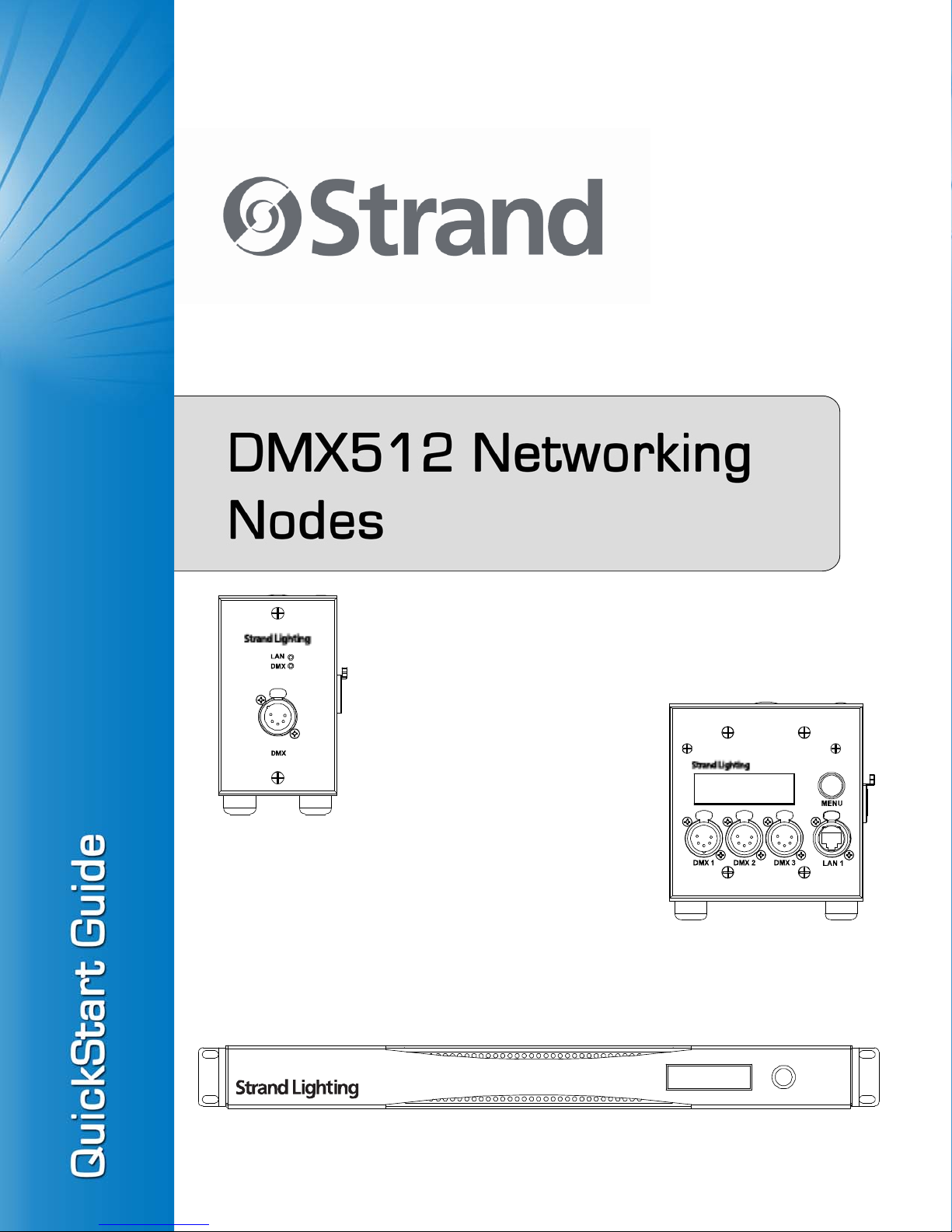
1. DMX512 Network Node Components
65161 - Single Port Node
DMX512
Connection (XLR5F)
NOTE: Unit can be flush mounted, surface mounted, or hung in truss.
Local Area Network
DMX512 Network Status LED
(LAN) Status LED
C-Clamp
Removable Rubber Feet (x4)
Network (POE) Connection
DMX512 Network Node Components 5
DMX512 Network Nodes QuickStart Guide
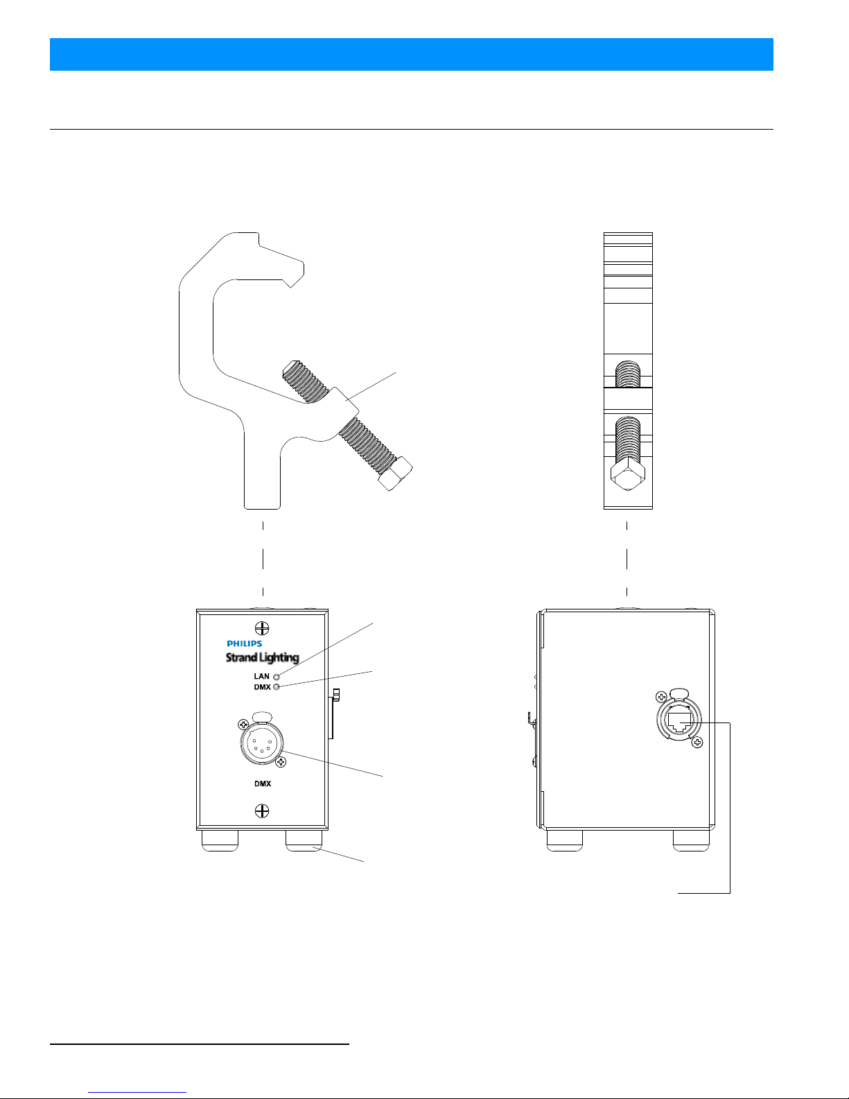
65163 - Three Port Node
DMX512 Connections
(3 Each, XLR5F)
LCD Information
Network Connection
(Not for POE)
Display
LCD Control
Rotary Button
NOTE: Unit can be flush mounted, surface mounted, or hung in truss.
Network (for POE) Connection
C-Clamp
Removable Rubber Feet (x4)

QuickStart Guide DMX512 Network Nodes
6DMX512 NETWORKING NODES - OVERVIEW
65168 - Eight Port Nodes
MENU
POWER INLET
100-250 VAC
.25 AMP 50-60 HZ
0.30 250V AMP SLOW FUSE
LAN 2 LAN 1
SHIELD
D-
D+
D2-
D2+
SHIELD
D-
D+
D2-
D2+
SHIELD
D-
D+
D2-
D2+
SHIELD
D-
D+
D2-
D2+
SHIELD
D-
D+
D2-
D2+
SHIELD
D-
D+
D2-
D2+
SHIELD
D-
D+
D2-
D2+
SHIELD
D-
D+
D2-
D2+
DMX 8 DMX 7 DMX 6 DMX 5 DMX 4 DMX 3 DMX 2 DMX 1
LAN 2 LAN 1 DMX 8 DMX 7 DMX 6 DMX 5 DMX 4 DMX 3 DMX 2 DMX 1
POWER INLET
100-250 VAC
.25 AMP 50-60 HZ
0.30 250V AMP SLOW FUSE
Local Area Network (LAN) 1
Ethernet Connection (RJ45)
AC Input Power
(input cable included with unit)
Rackmount Ear (x2, removable)
Local Area Network (LAN) 2
Ethernet Connection (RJ45)
Fuse (x2)
Compartment
DMX512 Connections
(8 Each, 5 Pin Phoenix Connectors)
Front of Unit (All 8-Port Models)
Rear of Unit (5-Pin Phoenix Connector Models)
LCD Control
Rotary Button
LCD Information
Display
Rear of Unit (5-Pin XLR5F Connector Models)
Fuse (x2)
Compartment Local Area Network (LAN) 1
Ethernet Connection (RJ45)
Local Area Network (LAN) 2
Ethernet Connection (RJ45)
DMX512 Connections
(8 Each, 5 Pin XLR5F Connectors)
AC Input Power
(input cable included with unit)

Power Requirements 7
DMX512 Network Nodes QuickStart Guide
INSTALLATION
1. Power Requirements
POE (Power Over Ethernet) Models (65161 or 65163)
All portable DMX512 Network Nodes are powered from a POE (Power Over Ethernet) compatible Ethernet Switch
or midspan/endspan POE injector using IEEE P802.3af-2003 power. The POE should be +48vdc. The unit shall draw
45mA with LCD backlight at full (65163 models only).
Rackmount Models (65168 or 65168-1)
Rackmount DMX512 Network Nodes are powered from standard AC wall sockets through the provided AC input
cable. The unit is auto-ranging from 100 - 240 VAC and the nominal current draw is 0.25 Amps with the LCD display
backlight at full.
Note: For all rackmount models, the socket-outlet shall be installed near the equipment and shall be easily
accessible. WARNING: Double Pole/Neutral Fusing / AVERTISSEMENT: Double Pole / Fusing Neutre.
2. Connecting a DMX512 Network
Basic DMX512 installation consists of connecting a DMX512 Network Node to a DMX512 controller in "daisy-
chain" fashion. A cable runs from the DMX512 controller to a DMX512 Network Node and to other DMX512
devices in the system. Note, the DMX512 Network Node does not have to be first device in the DMX512 signal
chain.
For more information on DMX512 networking and systems, refer to "Additional Resources for DMX512" on page 1.
3. Mounting - 65161 / 65163 Models
The 65161 DMX512 Network Node includes the faceplate, electronics, and a single-gang back box. This unit is
suitable for flush or surface wall mounting, sitting on a flat surface or hung in a truss (truss hook and mounting bolt
are included).
The 65163 DMX512 Network Node includes the faceplate, electronics, and a two-gang back box. This unit is suitable
for flush or surface wall mounting, sitting on a flat surface or hung in a truss (truss hook and mounting bolt are
included).
1
2
3
4
5
PUSH
DMX512 Connections
DMX512 Signal XLR Pin
Common (Drain) 1
DMX512 - 2
DMX512 + 3
No Connection 4
No Connection 5
XLR5F Type Connectors
DMX512 Connections
DMX512 Signal Phoenix Pin
Common (Drain) 1
DMX512 - (LAN1) 2
DMX512 + (LAN1) 3
No Connection 4
No Connection 5
5-Pin Phoenix Type
Connectors
SHIELD
D-
D+
D2-
D2+
DMX 8
12345

QuickStart Guide DMX512 Network Nodes
8INSTALLATION
Note: Installation should be done in full compliance of local and national codes.
Installation - 65161 or 65163 Flush Wall Mounting
To flush mount a 65151 or 65163 DMX512 Network Node:
Step 1. Determine a suitable location for unit to be installed.
Step 2. Prepare the wall by cutting an appropriate sized hole for the unit’s back box.
CAUTION: Before continuing, note that faceplate electronics is connected to a short internal Ethernet cable. Do not
damage cable in next step.
Step 3. If installed, remove faceplate with electronics from back box. Disconnect internal Ethernet cable from rear
of faceplate electronics. Set aside so faceplate and its electronics are safe from damage.
Step 4. Insert two supplied hole plugs into top of unit.
Step 5. Insert the back box in the wall and secure back box to structure using suitable hardware (by others).
Step 6. Connect network Ethernet cable to RJ45 connector on side of back box.
Step 7. Reconnect internal Ethernet cable to faceplate electronics.
Step 8. Reinstall faceplate.
Installation - 65161 or 65163 Surface Mounting
To surface mount a 65151 or 65163 DMX512 Network Node:
Step 1. Determine a suitable location for unit to be installed.
CAUTION: Before continuing, note that faceplate electronics is connected to a short internal Ethernet cable. Do not
damage cable in next step.
Step 2. If installed, remove faceplate with electronics from back box. Disconnect internal Ethernet cable from rear
of faceplate electronics. Set aside so faceplate and its electronics are safe from damage.
Step 3. Ensure that the back box is level by placing a spirit level on top of the box and mark the four mounting
holes.
Step 4. Drill four (4) holes in the wall and secure the back box to the wall using screws and suitable hardware (by
others).
Step 5. Reconnect internal Ethernet cable to faceplate electronics.
Step 6. Insert two supplied hole plugs into top of unit.
Step 7. Reinstall faceplate.
Step 8. The unit is ready for connection to network.
Installation - 65161 or 65163 Truss Mounting
To truss mount a 65151 or 65163 DMX512 Network Node:
CAUTION: Before proceeding, note that faceplate electronics is connected to a short internal Ethernet cable. Do not
damage cable in next step.
Step 1. If installed, remove faceplate with electronics from back box. Disconnect internal Ethernet cable from rear
of faceplate electronics. Set aside so faceplate and its electronics are safe from damage.
Step 2. Using supplied bolt, slide Belleville washer over bolt so washer will compress against back box when
tightened.
Step 3. Working inside of back box, insert bolt with washer through hole in top of back box.

Mounting - 65158 or 65158-1 Models 9
DMX512 Network Nodes QuickStart Guide
Step 4. Thread bolt into truss hook. Tighten bolt.
Step 5. The unit is ready for connection to network.
4. Mounting - 65158 or 65158-1 Models
To rack mount a 65168 DMX512 Network Node:
Note: Before installing, you will need four (4) rack screws that fit your specific rack (by others), at least 1U of rack
space available in the rack, and a place to connect the AC input cable. Do not connect to AC supply source at this
time.
Step 1. If rackmount ears are not attached, attach them to unit.
Step 2. If unit has rubber feet installed, unscrew them from unit. Keep for future use.
Step 3. Slide 65158 (or 65158-1) DMX512 Network Node into rack.
Step 4. Make data connections for LAN1, LAN2, and DMX networks (as applicable).
Step 5. Secure node into rack with four rack screws.
Step 6. Connect unit to AC power source.
Note: For all rackmount models, the socket-outlet shall be installed near the equipment and shall be easily
accessible. WARNING: Double Pole/Neutral Fusing / AVERTISSEMENT: Double Pole / Fusing Neutre.

QuickStart Guide DMX512 Network Nodes
10 OPERATION
OPERATION
1. Overview
The DMX512 Network Nodes described in this guide provides compact and cost effective networking solutions for
lighting facilities of any size.
The DMX512 Network Node is available is three basic configurations. For available models, refer to "About this
Manual" on page 3.
2. Node Configuration
Pre-Configuring DMX512 Network Nodes
DMX512 Network Nodes are configured at the factory with common default values. It is therefore necessary to
change the network configuration for each node before it is installed onto the network. It is logical that the
configuration of the DMX512 ports and the LCD setting should be done at the same time and each node labeled with
its IP Address ready for installation in the appropriate back box, auxiliary rack or dimmer rack.
The network default configuration for DMX512 Network Nodes is as follows:
Note: For configuration information, please download the current version of the Strand Net Software
Operation Guide from the Strand Lighting web site at www.strandlighting.com.
Field Value
IP Address 2.X.X.X
IP Netmask 255.0.0.0
DMX Universe Art-NET 0.0
DMX512 Network Node - Single Port (catalog number 65161) 11
DMX512 Network Nodes QuickStart Guide
PRODUCT SPECIFICATIONS
Note: Product specifications contained in this section are subject to change without prior notice. Refer to the product
specification sheets on the Strand Lighting web site for current information.
1. DMX512 Network Node - Single Port (catalog number 65161)
Input Power: Power Over Ethernet (PoE) supplied at Ethernet Port
Connections: DMX 5-Pin XLR Female Connector (bi-directional) - programmable DMX In or DMX out
with RDM
RJ45 (Ethernet) connector at side of back box
Communications: DMX512A, RDM, ShowNet, Streaming ACN, Art-Net, Vision.Net
Compliance: cETLus, CE, C-Tick, FCC, RoHS, IEEE (Ethernet)
Configuration: Via PhilipsStrandNet.exe application
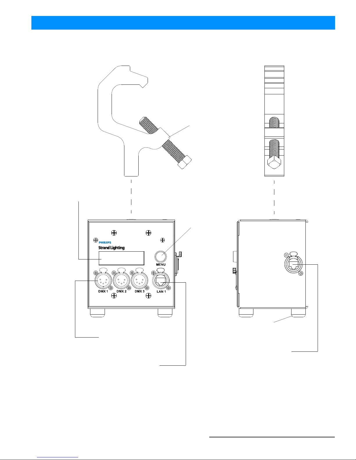
Weight: Node Only: 1.55 Lbs / 0.7 Kgs (with back box and rubber feet - no hook)
Truss Hook & Bolt: 0.95 Lbs / 0.45 Kgs
1.91 in
48.5 mm
5.06 in
128.5 mm
4.63 in
117.6 mm
2.75 in
70.0 mm
5.78 in
146.8 mm
3.74 in
95.0 mm

QuickStart Guide DMX512 Network Nodes
12 PRODUCT SPECIFICATIONS
2. DMX512 Network Node - Three Port (catalog number 65163)
Input Power: Power Over Ethernet (PoE) supplied at Rear Ethernet Port Only
Connections: DMX 5-Pin XLR Female Connector (bi-directional) - programmable DMX In or DMX out
with RDM
RJ45 (Ethernet) connectors (x2 - one on front and one at side of back box)
Communications: DMX512A, RDM, ShowNet, Streaming ACN, Art-Net, Vision.Net
Compliance: cETLus, CE, C-Tick, FCC, RoHS, IEEE (Ethernet)
Configuration: Via PhilipsStrandNet.exe application or LCD Display Menu
Weight: Node Only: 1.90 Lbs / 0.86 Kgs (with back box and rubber feet - no hook)
Truss Hook & Bolt: 0.95 Lbs / 0.45 Kgs
4.52 in
114.8 mm
4.63 in
117.6 mm
5.06 in
128.5 mm
3.74 in
95.0 mm
1.91 in
48.5 mm
5.78 in
146.8 mm

DMX512 Network Node - Eight Port (catalog number 65168) 13
DMX512 Network Nodes QuickStart Guide
3. DMX512 Network Node - Eight Port (catalog number 65168)
Input Power: 100 - 250VAC, 50/60 Hz, 0.25A (max)
Connections: Eight DMX Phoenix Connectors (bi-directional) - programmable DMX In or DMX
out with RDM
Two RJ45 (Ethernet) connectors at rear of unit
Communications: DMX512A, RDM, ShowNet, Streaming ACN, Art-Net, Vision.Net
Compliance: cETLus, CE, C-Tick, FCC, RoHS, IEEE (Ethernet)
Configuration: Via PhilipsStrandNet.exe application or LCD Display Menu
Weight: Node Only: 4.10 Lbs / 1.86 Kgs
4. DMX512 Network Node - Eight Port (catalog number 65168-1)
Input Power: 100 - 250VAC, 50/60 Hz, 0.25A (max)
Connections: Eight DMX 5-Pin XLR Female Connectors (bi-directional) - programmable DMX In or DMX
out with RDM
Two RJ45 (Ethernet) connectors at rear of unit
Communications: DMX512A, RDM, ShowNet, Streaming ACN, Art-Net, Vision.Net
Compliance: cETLus, CE, C-Tick, FCC, RoHS, IEEE (Ethernet)
Configuration: Via PhilipsStrandNet.exe application or LCD Display Menu
Weight: Node Only: 4.12 Lbs / 1.87 Kgs
6.29in
159.8 mm
0.26in
6.6mm
1.25 in
31.8 mm
17.42 in
442.5 mm
18.93 in
480.8 mm
18.53 in
470.7 mm
1.74 in
44.2 mm
1.99 in
50.5 mm
6.29in
159.8 mm
0.26in
6.6mm
1.25 in
31.8 mm
17.42 in
442.5 mm
18.93 in
480.8 mm
18.53 in
470.7 mm
1.74 in
44.2 mm
1.99 in
50.5 mm
DMX 8 DMX 7 DMX 6 DMX 5 DMX 4 DMX 3 DMX 2 DMX 1

This manual suits for next models
3
Table of contents
Popular Network Hardware manuals by other brands


Adaptive Recognition
Adaptive Recognition Carmen ANPR BOX Installation and user manual

COMEXIO
COMEXIO EnOcean Unit manual

HP
HP UPS Network Module user guide

Cisco
Cisco Wide Area Application Engine 612 Hardware installation guide

MSA
MSA FS-EZX-MOD-BAC Startup guide

ProfiTap
ProfiTap F4-10G-BP BYPASS TAP Installation and configuration manual


