MARKING OUT TOOLS
TOOLS YOU WILL NEED
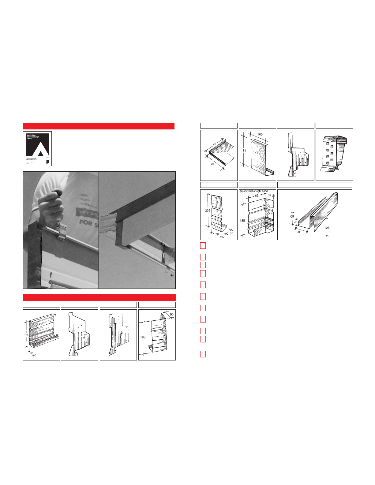
INSTALLING FASCIA
Square, string line, adjustable
bevel square & spirit level.
CUTTING TOOLS
Hacksaw, snips.
FIXING TOOLS
Hammer, drill, silicone, rivet gun
pliers.
OTHER USEFUL ACCESSORIES
Ladder, scaffold.
MEASURING YOUR PROJECT
Draw your roof outline and measure each fascia
length required, marking it on your plan.
For lengths longer than 9 metres, allow a joining
point adjacent to one rafter and mark the adjusted
fascia lengths on your plan.
BEFORE YOU START
Ensure that all materials are on site and double check
that the materials delivered correspond with your
order and initial take-off. Ensure that all tools are on
hand and that you have completely read and
understood the Clickfast Fascia and Gutter
installation instructions.
If further advice is needed contact your nearest
Stratco Sales Office before commencing.
MARKING OUT
Check rafter foot and plumb cuts are correct.
Determine the eave height, by reference to the
plans and by the location of soffit supports. The
soffit should finish at the top of the window reveal,
unless otherwise specified and the distance from the
top of the top plate to the window reveal should be
recorded (measurement A). Generally, this
measurement should only be taken from the highest
windows (usually the WC, laundry or bathroom).
Check at least two windows to confirm the height.
Determine the distance from the back of the fascia
base (by using a rafter bracket) to the outside
face of the wall frame (measurement B). It is
important to use a spirit level to ensure that the
bracket is plumb in taking this measurement.
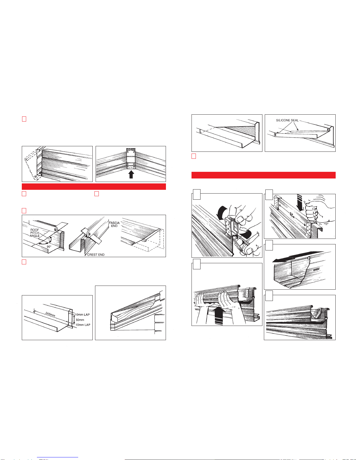
Measure barges by taking the actual roof length
from the top of the apex to the bottom of the
proposed fascia. Allow 300mm extra for laps and
angle cutting.
14
Deduct 60mm from measurement A and 50mm
from measurement B to provide two mark out
points for setting out a bracket. The mark out points
determine the back of the bracket and the centre slot.
4
Using an adjustable bevel square, spirit level and
tape, mark the bracket location on the second
last rafter from each end of a fascia run. Nail a
bracket (commencing with the first nail in the
adjustment slot) to the inside of each rafter. Fully nail
off each bracket with three nails.
5
1
2
3
Place a nail into the
foot cut of the rafter
on the two brackets from
Step 5, on the
measurement B-50mm
line and run a taut string
line between them.
6
Using a bevel square,
mark the location for the
back of the bracket on
every second rafter. Repeat
this process around the
building.
NOTE: An alternative
method is to put the string
line on the inside of the
soffit groove on the bracket.
To mark out the remaining
brackets, use a loose
bracket and the bevel
square in conjunction with
the string line. A final check
is made using a spirit level
against the bracket.
7
Complete your order form by summarising all
fascia and barge lengths, counting internal and
external mitres, and listing the number of brackets
and other accessories required.
Phone or fax your order to your nearest Stratco
outlet, clearly specifying delivery details and the
fascia and gutter finishes required.
5
6
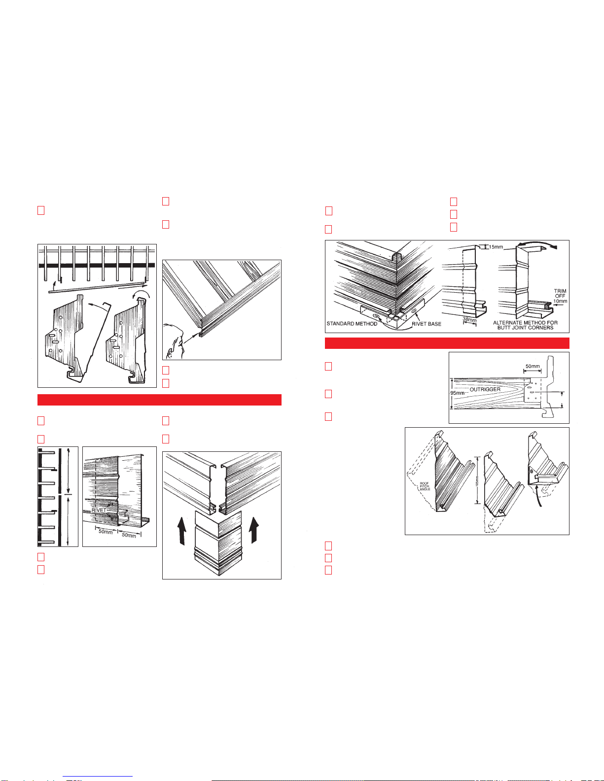
For internal corners not using butt joint method,
measure past the corner (approximately 1 metre,
and adjacent to a rafter) and mark the adjusted
lengths on your plan. If the butt joint method is used
lengths are measured to the actual corner.
3
2