5 ripple self-drilling screws V-shaped flashing
V-shaped flashing38x25mm rail four 3mm rivets
FENCE INSTALLATION
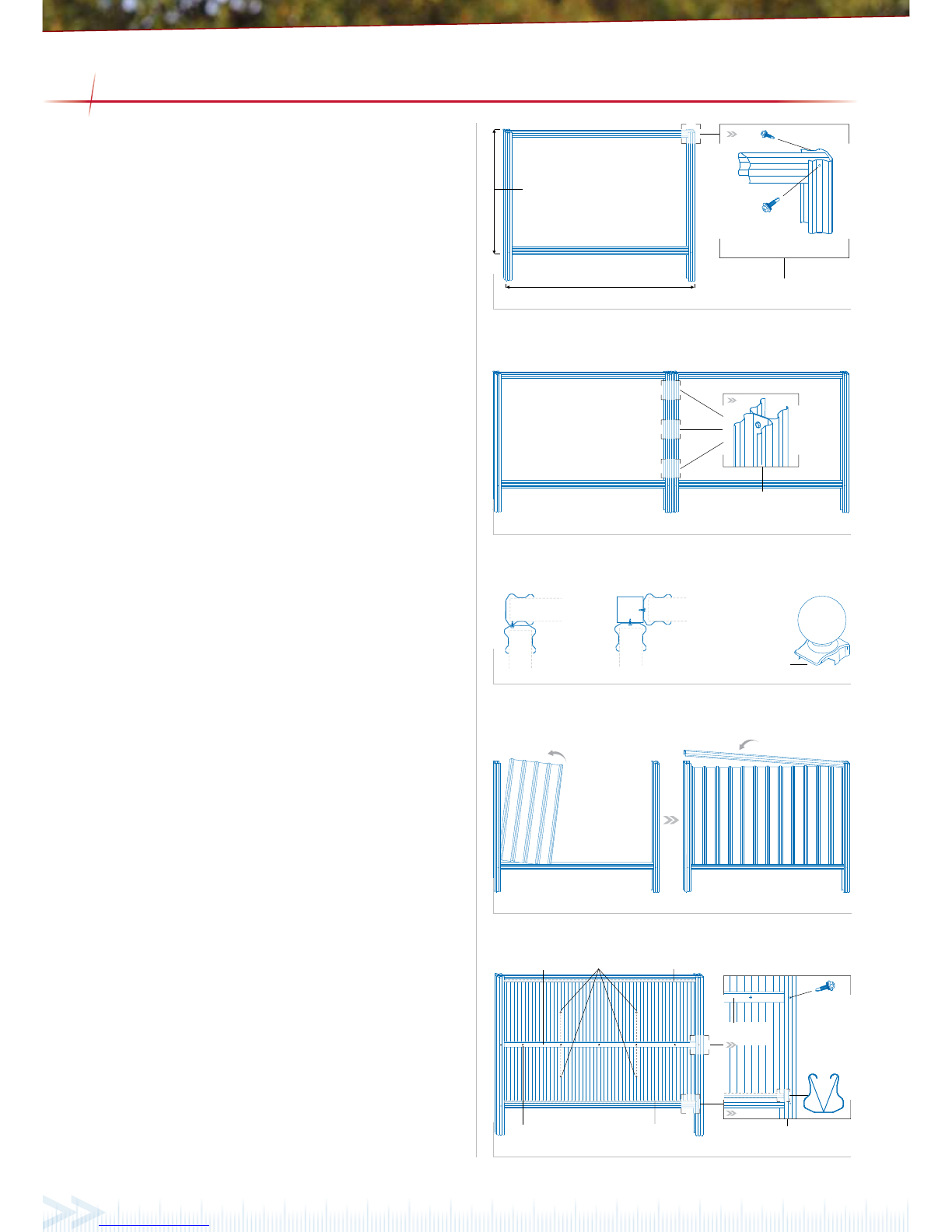
Figure 3.0
Fence panels should be installed starting from a gate post, free
end or corner. If you are working on sloped ground and intend to
step or slope the fence see the sections on the following page for
the correct installation procedure.
Assemble the framework
Lay the posts down on the ground and insert the top and bottom
track. Fix the tracks using a 10x16mm screw on each side of
both ends, see Figure 3.0. The top track should be ush with
the top of the post, unless you are installing a screen top, in
which case the post will need to extend 300mm past the track. If
SHS posts are required, they should be xed to the fence at this
stage using three 10x16mm screws. Caps should be inserted on
top of the SHS posts to prevent water entering. When extending
from a concreted gate post the frame will need to be assembled
vertically in position.
Extending the fence
Assemble the second panel and x it to the rst using three
10x16mm self drilling screws, refer to Figure 3.1. Place the
fence into the footing holes. If you are using SHS posts, ensure
they are installed between the panels. Prop the fence into the
correct position and concrete the joined posts into place. Refer
to ‘Preparing Footings’ for the correct method of concreting
the posts. Frames should be assembled and added one at time,
concreting the footings as you install each frame.
When joining around a corner, the posts can be xed directly to
each other or both posts xed to an SHS coloumn, refer to Figure
3.2. The SHS method must be used if the design calls for the
panels to have SHS posts. Post caps and ball caps can be used on
a corner post, provided the bottom of the cap is cut to t on one
end, so the cap can sit ush.
Installing the sheets
After the concrete has been allowed to cure for at least 48 hours
the fence sheets can be installed. Working on one panel at a time,
take o the top track by removing the screws holding it in place.
The sheets can now be positioned in the frame. Each sheet should
be rotated into position as shown in Figure 3.3, ensuring the
correct sheet overlap. (refer to Figure 3.5) The top track can now
be reinstalled. Starting at one end and working down to the other,
push the track into position, making sure the track is rmly in
place. To minimise rattling, the sheets should be xed together
at the overlaps using a 3mm rivet midway up the sheet. In wind
speeds W41 and greater, fasten the sheets to the tracks at each
of the overlaps using 10x16mm screws.
Completing a CGI Mini Panel
For CGI mini, two V-shaped ashings are provided. The V-shaped
ashings slide into the tracks with the point of the ‘V’ to the
outside of the panel. A 38x25mm internal rail is installed on one
side. The rail is positioned in the gap between the sheet and post,
half way down the panel. Angle the rail into position and x the
rail to the post using a 10x16mm screw at each end. The sheets
are then xed to the rail using ve 10x20mm ripple self-drilling
screws per sheet ensuring it is fastened at each overlap. Sheets
should be xed together at the overlaps using four 3mm rivets
midway between the tracks and internal rail, see Figure 3.4.
Figure 3.3
Figure 3.2
Figure 3.1
Figure 3.4