StreetStrider 3i User manual

!
!
!
StreetStrider 3i and 7i
OWNER’S MANUAL
16321 Gothard Street, Suite E
Huntington Beach CA 92647
1-800-348-0998
www.StreetStrider.com
©September 2016

!
23i and 7i / Owner’s Manual
OWNER’S MANUAL CONTENTS PAGE .
1. About This Manual 2
2. Parts Identification 3
3. Assembling the StreetStrider 3i and 7i 7
3.1 Unpacking and Prep 7
3.2 Wheels 8
3.3 Poles and Skis 10
3.4 Rear Hub, Chain and Shifter 11
3.5 Brakes 13
3.6 Front Wheel Alignment 14
3.7 Folding 14
4. Simple Steps to Learn to Stride 15
5. Safety Equipment 15
6. Mechanical Safety Check 16
7. Limited Warranty 17
8. Return Policy 18
RECORDS .
Register your StreetStrider online at www.StreetStrider.com so we can notify you about
new models,care and maintenance issues, and record yourserial number. You may
also want to register your serial number with your local police department in the event that your StreetStrider is lost or stolen.
1. About This Manual .
This StreetStrider 3i and 7i Owner’s Manual contains important assembly, maintenance, safety and performance information. It was written to
help you get the most performance, comfort, enjoyment and safety out of your new StreetStrider. Keep this manual handy for future reference.
IMPORTANT: If your StreetStrider was purchased unassembled, read this manual before you assemble it. The Limited Warranty
found in this manual on page 17 applies only to StreetStriders that comply with the assembly instructions in this Owner’s Manual.
IMPORTANT: You should read this manual before you go out on your first ride.
Riding a StreetStrider can be a hazardous activity even under the best of circumstances. It is highly recommended that your first stride on your
new StreetStrider be taken in a controlled environment, away from cars, obstacles and other cyclists, and wearing your helmet.
Proper maintenance of your StreetStrider is your responsibility as it reducesthe risk of injury. This manual contains many IMPORTANT,
CAUTION and WARNING statements concerning the consequences of failure to maintain or inspect your StreetStrider. When inspecting your
StreetStrider, be certain to secure all parts properly as described in Table 2-1. Under-tightening or over-tighteningcan result in component
damage. StreetStrider parts have metric hardware - always use the correct tools.
IMPORTANT: It is impossible to predict every condition that will occur while striding. StreetStrider (the Company) has made no
representation about the safe use of the StreetStrider under all conditions. There are risks associated with the use of any
StreetStrider that cannot be predicted or avoided, and the Company recommends safe and cautious striding.
WARNING Failure to read and comply with all assembly, safety, performance and
maintenance requirements and warnings, and unsafe or improper use of the StreetStrider
could result in serious injury or death.
Record your StreetStrider model, serial number (on the frame under the bottom bracket; see photo)
and other information below. Retain your sales receipt as proof of purchase.
MODEL ________COLOR____________SERIAL NUMBER__________________________
DATE OF PURCHASE_______________PLACE OF PURCHASE_____________________
!
!

!
3i and 7i Owner’s Manual 3
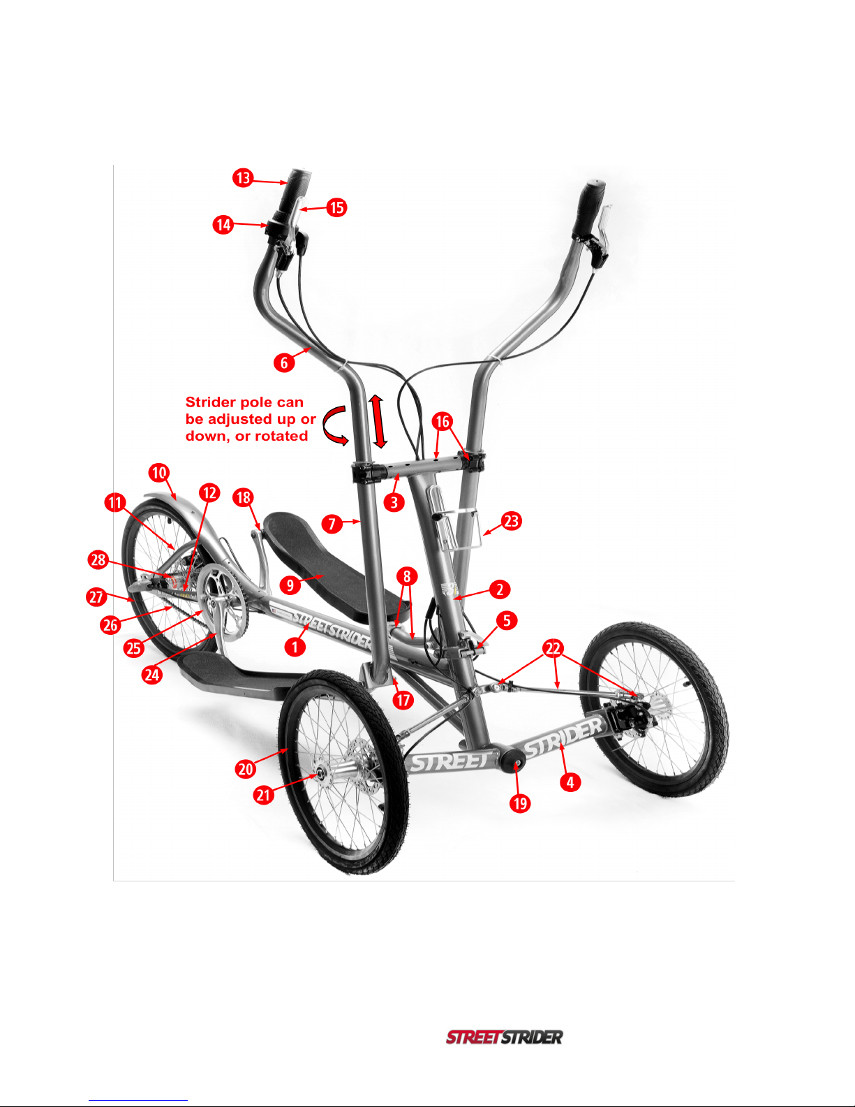
2. Parts Identification
Table 2-1. StreetStrider Parts List with Hardware Specifications,Quantity,and Maintenance State.
Parts are numbered in subsequent figures.
#
DESCRIPTION
HARDWARE
SPECIFICATIONS
QTY
STATE
1
Main frame bone
1
2
Head tube
1
3
Crossbar
1
4
Front beam
1
5
Fold joint
Quick Release clamp
stem nylon lock nut
M6 x P1.0 x L20 x H10 x W10
1
Snug for secure
clamp operation
6
Stride pole upper
Left and right side
2
7
Strider pole lower
2
8
Striderski
Quick release clamp
Composite bushings
Roller bearings
Left and right side, QR on right ski
OD12 x ID10 x L15 x 17 mm flange, at Joint #2
OD 25 x ID 18 x L 20, at Joint #3
2
4
4
Tighten
9
Foot platform
4 mm hex screw,
M5 x P0.8 x L12 x H12 x W4, flat head
12
Tighten
10
Rear fender frame
4 mm hex screw,
M5 x P0.8 threaded hole for luggage rack
1
11
Fender stay
2
12
Chain stay
2
13
Hand grip
Left and right side, rubber
2
14
Twist grip shifter
3mm hex screw
M5 x P0.8 x L12 x W3, clamp
1
Tighten
15
Brake lever
5 mm hex screw
Parking pin
Cable housing adjuster
Cable doubler
M5 x P0.8 x L20 x H10 x W5, clamp
OD 10, spring loaded
M10 x P2.0 barrel adjuster with lock ring
Front brake, with adjuster and lock ring
2
2
2
1
Tighten
Adjust-lock
Adjust-lock
16
Joint #1, cross bar-pole
pivot clamp assembly
4mm hex screw
6 mm hex spindle
3 mm hex set screw
3 mm hex set screw
Composite bushings
M5 x P0.8 x L25 x H8 x W4, clamp cap
M14 x P2.0 x L20 x H18 x W6, clamp base
M6 x P0.8 x L10, with cone end, clamp base side
M6 x P0.8 x L6, with cup end, cross bar
OD21 x ID18 x L25 x 26 mm flange, in cross bar
8
2
2
8
4
Tighten evenly to
secure pole
Tighten
Tighten
Snug but allow
joint movement
17
Joint #2, pole-ski pivot
8mm hex screw,
washer,
17 mm nut
M10 x P1.5 x L75 x H15 x W8
OD16 x ID10 x T1
M10 x P1.5 x L10 x W17, nylon lock
2
2
2
Snug but allow
joint movement
18
Joint #3, ski-pedal pivot
6 mm hex spindle
OD18 X L60 x W6, thd 9/16" right and left, C clip
2
Tighten
19
Front beam pivot
8 mm hex screw
3 mm hex set screw
Tapered roller bearing
M10 x P1.5 x L20 x W8, front cap
M6 x P0.8 x L10 x W3, rear end
OD 47 x ID 20 X T15
1
1
2
Tighten
Tighten
20
Front wheel and tire
Tire 16”x 1 3/8”, 37 x 349, 80 psi
2
21
Front wheel hub
19 mm hex axle nut
M12 x P1.75 x L10 x W19, nylon lock
2
Tighten
22
Steering linkage
Inboard and outboard
rod ends
Threaded linkage rod
M8 x P1.25 x L20 x W14 flats on stud
M8 x P1.25 x L10 x W13 nylon lock nut
M8 x P1.25 x L20 rod, right and left thread ends
M8 x P1.25 x L5 x W14, right and left jam nuts
4
2
4
Tighten
Tighten
Tighten

!
43i and 7i / Owner’s Manual
23
Bottle cage
4 mm hex in boss
M5 x P0.8 x L12 x H10 x W4, socket
2
Tighten
24
Crank arm set with
Bottom bracket
8 mm hex screw
Square taper
M8 x P1.0 x L15 x H12 x W8, 18 mm flange
68 x 122 mm
2
1
Tighten
Tighten
25
Chain ring with guard
52 T
1
26
Chain
1/2" x 1/8" x 93 links
1
27
Rear wheel and tire
Tire 20” x 1 3/8”, 37 x 451, 80 psi
1
28
Internal gear hub
15 mm axle nuts
3 or 7 speed, 3/8” x 26 tpi x W15 axle nuts
2
Tighten
29
Front disc brake
5 mm hex mount screw
5 mm hex caliper screw
5 mm hex outer pad
3 mm hex inner pad
Cable housing adjuster
4 mm hex cable clamp
M6 x P1.0 x L15 x H10 x W5, through knuckle
M6 x P1.0 x L15 x H10 x W5, through bracket
W5 outer pad adjuster with 2 mm lock set screw
W3 inner pad adjuster, through center screw hole
M6 x P1.0 x L15 knurled for fingers with lock ring
M5 x P0.8 x L12 x H10 x W4, socket and nut
4
4
2
2
2
2
Tighten
Adjust-tighten
Adjust-tighten
Adjust
Adjust-lock
Adjust-tighten
30
Front disc rotor
4mm hex screw
M5 x P0.8 x L10 x H10 x W4, pan head
12
Tighten
31
King pin bolt in front
beam clevis
8 mm hex bolt
washer
17 mm nut
M10 x P1.5 x L75 x H15x W8, socket
OD16 x ID10 x T1
M10 x P1.5 x L10 x W17, nylon lock
2
2
2
Snug but allow
knuckle swivel
32
Steering knuckle w/
lean stop
4mm hex screw
Lean stop disc
Composite bushing
M6 x P1.0 x L15 x H10 x W5, socket screw
W10 nylon lock nut
OD18 x T4 with 6 mm offset hole
OD12 x ID10 x L15 x 17 mm flange
2
4
Adjust-tighten
33
Bell crank for 3 speed
hub
2.5 mm hex screw
M5 x P0.8 x L6 x W2.5 set screw
Gear alignment window
Shift cable barrel adjuster
1
1
Snug to secure
Adjust
34
Rear disc brake
5 mm hex mount screw
5 mm hex caliper screw
5 mm hex outer pad
3mm hex inner pad
Cable housing adjuster
4 mm hex cable clamp
M6 x P1.0 x L15 x H10 x W5, through drop out
M6 x P1.0 x L15 x H10 x W5, through bracket
W5 outer pad adjuster with 2 mm lock set screw
W3 inner pad adjuster, through center screw hole
M6 x P1.0 x L15 knurled for fingers with lock ring
M5 x P0.8 x L12 x H10 x W4, socket and nut
2
2
1
1
1
1
Tighten
Adjust-tighten
Adjust-tighten
Adjust
Adjust-lock
Adjust-tighten
35
Rear disc rotor
4mm hex screw
M5 x P0.8 x L10 x H10 x W4, pan head
6
Tighten
36
Rear drop out
Dropout slot for rear hub axle
Holes for rear brake mounting bracket
M5 x P0.8 hole for rear luggage rack screw
2
4
2
37
Shifter cassette for 7 sp
Cassette pulley and lock ring on 7 sp hub
1
Install-lock
M=OD of threads, mm
L=length
W=wrench fit, mm
Specification
Key
P=pitch, threads/mm
H=OD of head
T=washer thickness, mm
!
3i and 7i Owner’s Manual 5
Figure 2-1. StreetStrider 3i and 7i Parts. Refer to Table 2-1 for part numbers and descriptions.
!
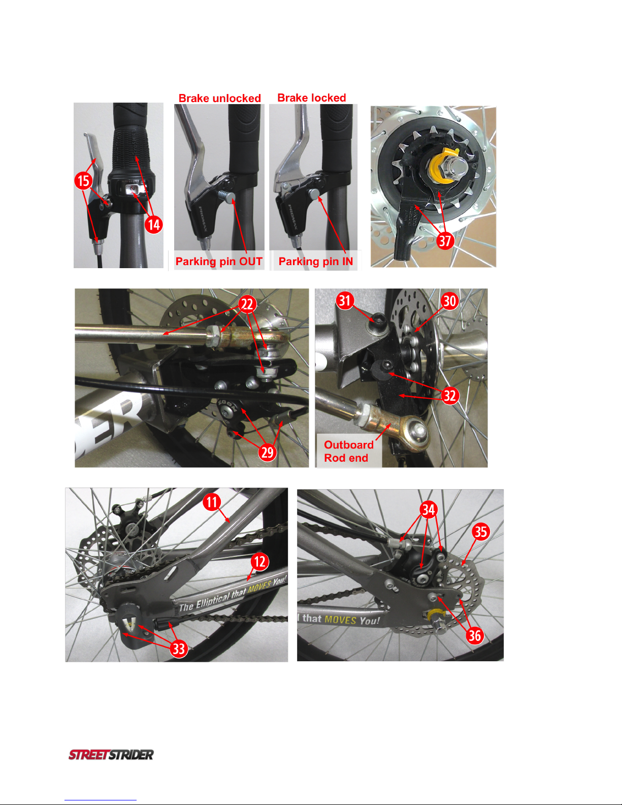
63i and 7i / Owner’s Manual
Figure 2-2. StreetStrider 3i and 7i Parts. Refer to Table 2-1 for part numbers and descriptions.

!
3i and 7i Owner’s Manual 7
3. Assembling the StreetStrider 3i and 7i …… …. …
To assemble your StreetStrider 3i or 7i,first view the StreetStrider assembly videos provided to you on the StreetStrider DVD, then follow the steps
and photos in this chapter. Included in the shipping box are the StreetStrider in parts, and asmall bundle in the top tray inside the box containing
the StreetStrider Owner’s Manual, Assembly Checklist, StreetStrider DVD, tool kit, bagsof assembly parts, 2 spare inner tubes, and reflectors. The
tool kit contains a 19 mm socket, 17 x 14, 15 x 13, 14 x 12, and 13 x 12 mm open end wrenches, 2, 2.5, 3, 4, 5, 6 and 8 mm hex wrenches, and 2
tire levers. Parts include: a front beam bearing assembly, 28 mm crank arm bolts, a shifter push rod for the 3i, and a cassette pulley for the 7i.
3.1. Unpacking and Prep (see video) .
Figure 3.1-1. Unpacking
The StreetStrider box has graphics to show which side is up (Fig. 3.1-1a). The top tray in the box holds the parts bundle (Fig. 3.1-1b),and the
support layers underneath protect the StreetStrider components. The front wheel assembly and rear wheel are the next 2 layers (Fig. 3.1-1c).
Remove the wheels and set aside.
Figure 3.1-2. Removing Padding
The main frame assembly is on the bottom layer (Fig. 3.1-2a). Using the corner cut-outs to grip the bottom cardboard panel, lift that panel and the
folded StreetStrider out of the box, set the unit on top of the box or table,and remove the remaining zip ties (Fig. 3.1-2b). Set the foot platform
assemblies (lower pole, ski, foot platform, crank arm) aside, then lift the frame with upper poles attached by cables off of the lower panel and set
upright on the table (Fig. 3.1-2c).
Figure 3.1-3. Moving the Chain
Remove the packing material from the chain that’s wrapped around the right fender stay (Fig. 3.1-3a). Move the loop of chain down the fender
stay, around the dropout (Fig. 3.1-3b), and forward along the chain stay so the loop of chain can wrap around the bottom bracket shell (Fig. 3.1-
3c).
IMPORTANT: Save the box and packing material as they must be used to repack the StreetStrider for any returns.
TERMINOLOGY: The right and left sides of the StreetStrider refer to sides when one is striding.

!
83i and 7i / Owner’s Manual
3.2. Wheels (see video) .
Figure 3.2-1. Front Beam Shaft
Retrieve the front beam shaft assembly and take the cap, bearings and back plate off the shaft (Fig. 3.2-1a). Roll the StreetStrider onto it’s left side
and loosen the set screw under the front beam shaft tube with a 3 mm hex wrench (Fig. 3.2-1b). Slide the shaft all the way into the tube from the
rear so that the flat section on the rear end of the shaft fits just above the 3 mm set screw (Fig. 3.2-1c), and then tighten the set screw.
IMPORTANT: Make sure there is some grease on the shaft and bearings.
Figure 3.2-2. Front Beam and Wheels
Slide the back plate and one of the tapered bearings, with taper facing forward, onto the shaft (Fig. 3.2-2a). Unfold the front wheels on the front
beam and set the assembly in front of the StreetStrider frame. Lift the frame up and slide the shaft with rear bearing into the bearing housing in the
center of the beam (Fig. 3.2-2b). Insert the other tapered bearing onto the shaft with the taper facing rearward (Fig. 3.2-2c). Place the black cap
over the front of the beam and shaft, insert the 10 mm screw, and tighten with the 8 mm hex wrench (Fig. 3.2-2d).
IMPORTANT: We recommend adding a liquid thread locker to the threads of the 10 mm screw.
!
Figure 3.2-3. Steering Linkages
Lower the left steering linkage so the outboard rod end can be secured to the left steering knuckle (Fig. 3.2-3a). Unscrew the 13 mm nylon lock nut
from the rod end stud, insert the threaded stud through the hole at the forward end of the steering knuckle, secure the stud with the nylon nut having
one washer above and one washer below the knuckle (Fig. 3.2-3b),and then hold the stud and tighten the nut using two 13 mm wrenches (Fig.
3.2-3c). Repeat steps to attach the right steering linkage (Fig. 3.2-3d). IMPORTANT: Inflate tires to 80-85 psi.
Figure 3.2-4. Front Brake Cables
Route the front brake cables from the cable
doubler on either side of the head tube, under the
steering linkage and over the front beam (Fig. 3.2-
4a). Insert the left and right cable and housing
into the barrel adjuster on the left and right brakes,
respectively (Fig. 3.2-4b).
!
!
3i and 7i Owner’s Manual 9
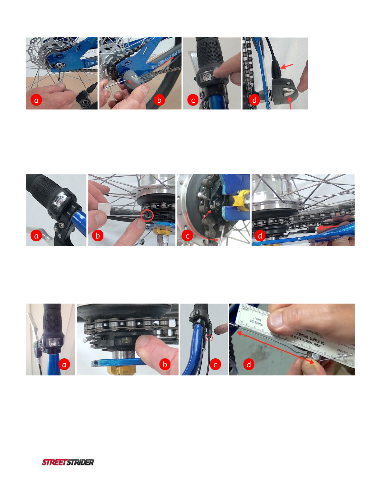
Figure 3.2-5. Rear Wheel on 3i
Retrieve the 3-speed rear wheel, remove any cardboard packing from the right axle end that
covers the sprocket, remove the black plastic cover pressed over the silver acorn nut on the left
axle end, then lift the rear fender, slide the wheel between the dropouts and rest the fender on
the tire (Fig. 3.2-5a). On the right side, loop chain over sprocket and unscrew hex nut so there
is an exposed section of axle that can slide into the dropout (Fig. 3.2-5b). On the left side, align
the brake rotor with the brake caliper gap and unscrew acorn nut so there is an exposed section
of axle that can slide into the dropout (Fig. 3.2-5c). Slide axle into dropouts all the way forward,
align the tongue of the yellow non-turn washer on the left axle end with dropout slot, and finger
tighten the axle nuts on both ends (Fig. 3.2-5d).When finished, rear wheel axle is in dropouts
and fully forward, axle nuts are finger tight, and chain is looped over sprocket at the rear and
over bottom bracket shell at the front (Fig. 3.2-5e). IMPORTANT: Inflate tires to 80-85 psi.
!
.
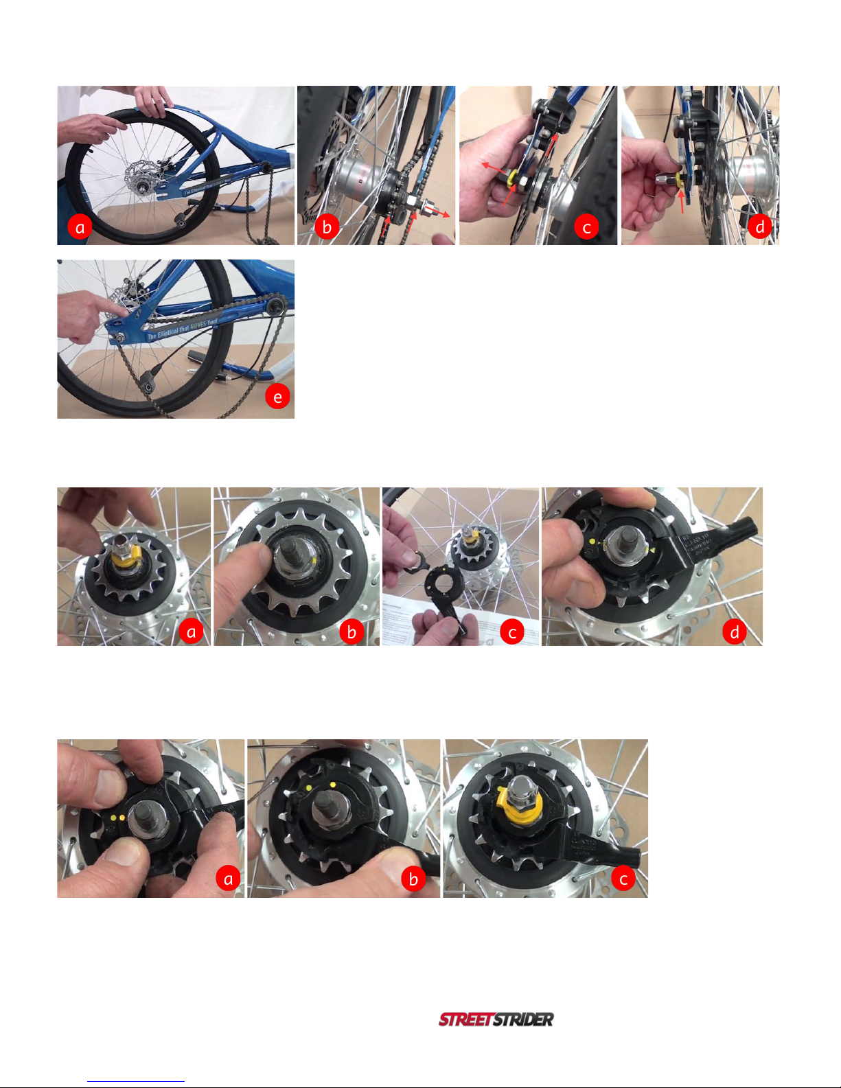
Figure 3.2-6. Rear Wheel Hub on 7i
Retrieve the 7-speed rear wheel, remove any cardboard packing from the right axle end that covers the sprocket, remove the black plastic cover
pressed over the silver acorn nut on the left axle end. Remove the silver acorn nut and yellow non-turn washer from the right axle end (Fig. 3.2-6a).
Locate the 2 yellow dots on the silver washer (Fig. 3.2-6b). Locate the shifting cassette pulley and the lock ring in the parts bag (Fig. 3.2-6c).Place
the shifting cassette pulley over the axle so that the yellow dots on the washer and the cassette pulley are in line (Fig. 3.2-6d).!
Figure 3.2-7. Rear Wheel Hub on 7i
Put the lock ring over the axle so that the 2 yellow dots are adjacent (Fig. 3.2-7a). Rotate the lock ring 45° clockwise to lock the cassette pulley
onto the hub (Fig. 3.2-7b).Replace the yellow non-turn washer with tongue pointing rearward, and screw the acorn nut back onto the axle a few
turns (Fig. 3.2-7c).

!
10 3i and 7i / Owner’s Manual
Figure 3.2-8. Rear Wheel on 7i
Lift the rear fender, slide the wheel between the dropouts and rest the fender on the tire (Fig. 3.2-8a). On the right side, loop chain over sprocket.
On the left side, align the brake rotor with the brake caliper gap.Unscrew acorn nuts on each end of the axle so there is an exposed section of axle
under the non-turn washers that can slide into the dropouts (Fig. 3.2-8b).Slide axle into dropouts all the way forward, align the tongue of the non-
turn washers with dropout slots, finger tighten the acorn nuts on both ends,and loop chain from hub sprocket at the rear and over bottom bracket
shell at the front (Fig. 3.2-8c). IMPORTANT: Inflate tires to 80-85 psi.
3.3. Poles and Skis (see video) .
Figure 3.3-1. Head Tube
Using the 4 mm hex wrench, remove the 4 screws and caps from the pole clamp at Joint #1 (Fig. 3.3-1a). Rest the upper poles on the main frame
and unfold the head tube (Fig. 3.3-1b). Slide the quick release clamp pin to the right (Fig. 3.3-1c), lift the head tube to the full upright position and
close the quick release lever (Fig. 3.3-1d). !
Figure 3.3-2. Lower Poles
Retrieve the right foot platform assembly (lower pole, ski, foot platform, and crank arm with chain ring) and position next to right side of the frame
(Fig. 3.4-2a). Rotate the Joint #1 clamp base so the set screw is on bottom (Fig. 3-3-2b).The function of the 4 set screws on each end of the
crossbar (Fig. 3.3-2c) is to adjust the fit of the bushings inside the crossbar so the Joint #1 clamp assembly is snug and rotates smoothly. If the
Joint #1 clamp is too tight, loosen each set screw ¼turn. If the Joint #1 clamp is too loose or has too much play, tighten each set screw ¼turn.
IMPORTANT: Do not over tighten the 4 set screws. Lift the lower pole,insert it into the clamp base,and install the clamp cap with the 4 caps
screws using the 4 mm hex wrench. Make sure there is an equal gap between cap and base in the front and rear of the clamp,but do not tighten
the screws yet (Fig. 3.4-2d).
IMPORTANT: We recommend adding a little grease to the threads of the 4 cap screws.
!
!
3i and 7i Owner’s Manual 11
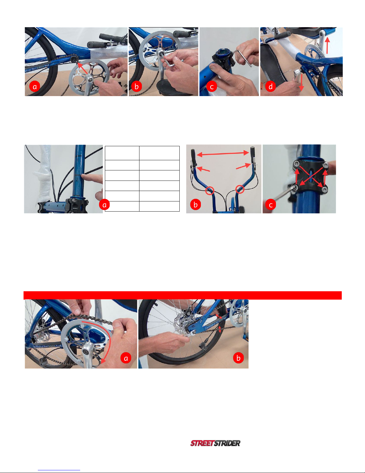
Figure 3.3-3. Skis
Lift the right crank arm so it is in the 6 o’clock position and insert it onto the Bottom bracket square spindle (Fig. 3.3-3a). IMPORTANT: Make sure
there is a little grease on the spindle so the crank arm slides on firmly. Retrieve an 8 mm crank bolt, screw it into the spindle to secure the
crank arm,and tighten with the 8 mm hex wrench (Fig. 3.3-3b). Attach the left lower pole in the Joint #1 clamp as done on the right side (Fig. 3.3-
3c). Rotate the right crank arm to the 12 o’clock position and insert the left crank arm,in the 6 o’clock position,onto the bottom bracket spindle.
As done on the right side, insert the other 8 mm crank bolt and tighten to secure the left crank arm (Fig. 3.3-3d).
Figure 3.3-4. Upper Poles
Insert the upper poles into the lower poles. The right upper pole has the twist grip shifter and brake lever. IMPORTANT: Make sure there is a
little grease on the pole end so it slides in easily. The pole height lines (black or white) are used to set the approximate pole height for the
height of the user, from < 5’ to approximately 7’ (see table and Fig. 3.3-4a). IMPORTANT: A good starting pole height will position the user’s
arm to have a 90° elbow bend,with forearm parallel to the ground when standing on the platforms and holding the grips of both poles in
vertical position. Rotate the poles so the grips are approximately shoulder width of the user (Fig. 3.3-4b). With the 4 mm hex wrench, carefully
tighten the Joint #1 clamp in an X pattern (Fig. 3.3-4c) so that all the screws are tightened evenly and the space between the clamp base and cap
on the front side of the pole is equal to the space on the rear side.Finally, position the brake levers forward, in front of the grips, and tighten the
brake clamp with a 5 mm hex wrench. Then rotate the shifter so the gear window faces the user,and tighten the shifter clamp with a 3 mm hex
wrench. Secure the shifter and brake cablesto the poles with zip ties (Fig. 3.3-4b).
3.4. Rear Hub, Chain and Shifter (see video) .
Figure 3.4-1. Chain
Lift the chain off the Bottom bracket and wrap around the right crank arm chain ring (Fig. 3.4-1a). Pull the rear wheel backward to make the chain
taught, center the front of the wheel in the frame chain stays, then tighten the axel nuts using the 15 mm wrench (Fig. 3.4-1b). A taught chain
should only move about ½” if lifted at a point midway between the chain ring and hub sprocket (Fig. 3.4-1b).
Pole
Height
User Height
(cm)
1
5’ 0” (152)
2
5’ 6” (168)
3
6’ 0” (183)
4
6’ 6” (198)
STOP
7’ 0” (213)
!
12 3i and 7i / Owner’s Manual
Figure 3.4-2. Shifting Gears on the 3i
Retrieve the 3-speed shifter push rod from the parts bag and insert it into the hole on the right end of the axle (Fig. 3.4-2a), then attach the bell
crank to the right axle by fitting it over the push rod and right axle nut as close to the drop out as possible, with the shifter cable routed along the
lower edge of the frame chain stay, then securing it by tightening the 2.5 mm set screw with the 2.5 mm hex wrench (Fig. 3.4-2b). IMPORTANT:
Do no over tighten the 2.5 mm set screw. Set the twist grip shifter in 2nd gear (Fig. 3.4-2c). On the bell crank, make sure the interior thicker
yellow line under the gear alignment window is between the two thinner yellow lines on the window. If needed, use the shifter cable barrel adjuster
at the front of the bell crank to move the interior line to the correct 2nd gear position (Fig. 3.4-2d).
Figure 3.4-3. Shifter Connections on the 7i
Set the 7-speed shifter to gear 1 (Fig. 3.4-3a), then insert the 2 mm hex wrench (or short spoke) into the hole of the cassette pulley tab located at
the 9 o’clock position (Fig. 3.4-2b) and rotate the wrench to the 6 o’clock position so the cable fixing screw can be inserted into the oblong slot on
the cassette pulley, now in the 9 o’clock position, with the nut facing outward (Fig. 3.4-2c). While holding the wrench at the 6 o’clock position, insert
the black plastic ferrule on the end of the cable housing into the socket at the end of the cassette pulley arm (Fig. 3.4-2d),then return the wrench to
the 9 o’clock position making sure the cable lies in the groove under the cassette pulley.
Figure 3.4-4. Shifting Gears on the 7i
Set the 7-speed grip shifter to gear 4 (Fig. 3.4-3a), then check the gear alignment window on the hub cassette pulley to make sure the 2 yellow
lines are aligned (Fig. 3.4-2b). If the lines are offset,turn the barrel adjuster located where the shifter cable enters the grip shifter (Fig. 3.4-2c)until
the 2 yellow lines align (Fig. 3.4-2b). If turning the barrel adjuster is not sufficient to align the 2 yellow lines, shift to gear 1, separate the shifter
cable from the cassette pulley and make sure the free cable, from the ferrule at the end of the housing to the center of the fixing screw,is 100 mm
long (Fig. 3.4-2c). If not, loosen the fixing screw/nut, reposition it to the 100 mm length, tighten the fixing screw/nut, and reinstall the cable onto the
cassette pulley.
!
3i and 7i Owner’s Manual 13
3.5. Brakes (see video) .
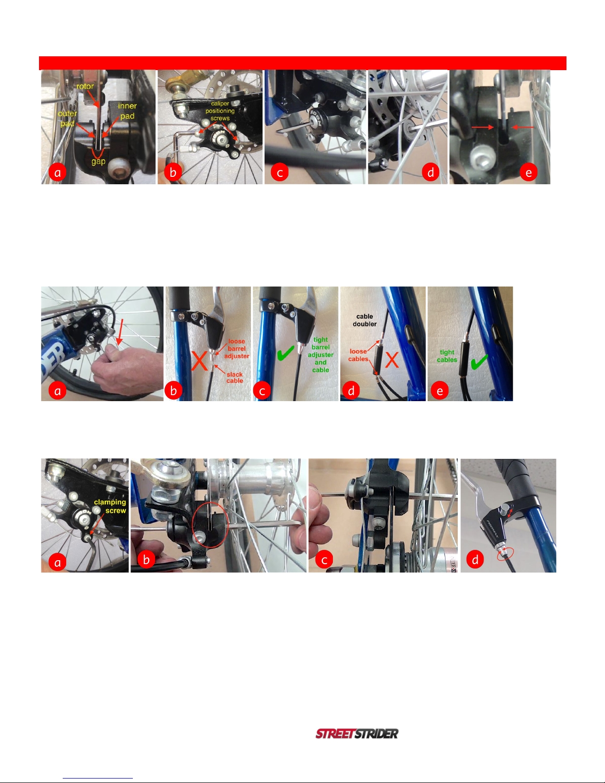
Figure 3.5-1. Front Brake Calipers
To correctly position the brake pads, the brake pads must first be pressed tight against the disc brake rotor. To do that, first check to make sure the
disc brake rotor is in the center of the caliper gap (Fig. 3.5-1a). If the rotor is in the center of the gap, proceed by skipping the next sentence.If the
rotor is not in the center of the caliper gap,loosen the 2 caliper positioning screws with a 5 mm hex wrench (Fig. 3.5-1b). To press the brake pads
tight against the rotor,insert the 3 mm hex wrench through the center screw on the caliper lever (Fig. 3.5-1c) and insert the 5 mm hex wrench into
the outer pad back (Fig. 3.5-1d) and screw in the pad adjusters until the pads are tight against the rotor in the center of the gap (Fig. 3.5-1e). If the
caliper positioning screws had to be loosened, tighten them now. Using the same procedure, tighten the pads against the rotor in the center of the
caliper gap on the other front brake.
Figure 3.5-2. Connect Brake Cables
With the brake cable routed through the barrel adjuster on one front brake, pull the cable down firmly (Fig. 3.5-2a) to remove any slack or loose
cable at the brake lever and on either end of the cable doubler, as well as screw in the barrel adjuster at the brake lever (Fig. 3.5-2b-e). Pull the
cable down at the other brake to make sure there is no loose cable on that side as well.
Figure 3.5-3. Connect Brake Cables (con’t)
Loosen the clamping screw using the 4 mm hex wrench and thread the cable between the nut and the caliper lever, then pull the cable taught and
tighten the clamping screw (Fig. 3.5-3a). Clamp the cable on the other brake caliper the same way. Using the 3 mm and 5 mm hex wrenches,
unscrew the inner and outer pads to leave a small sliver of light between the rotor and the pads (Fig. 3.5-3b) so when the wheel rotates,the rotor
does not rub the pads. Repeat on the other brake. To make sure both front brakes stop equally,stand in front of the StreetStrider, squeeze the left
brake lever and pull the StreetStrider forward while slowly easing the brake pressure. If one wheel starts rotating before the other, which begins to
turn the StreetStrider, adjust the brake pads and/or the barrel adjuster at the caliper until that wheel begins to rotate with the other wheel.
The rear brake caliper is adjusted exactly as described for a front brake caliper (Fig. 3.5-3c). Finally, both brake levers have a parking brake pin to
hold the brake lever in a squeezed position (Fig. 3.5-3d). If the parking brake does not hold,unscrew the brake lever barrel adjuster (Fig. 3.5-3d).
IMPORTANT: Properly adjusted brakes will clamp the wheels when the brake lever is squeezed about 1 inch (25 mm).
!

!
14 3i and 7i / Owner’s Manual
3.6. Front Wheel Alignment (see video) .
Figure 3.6-1. Aligning the front wheels
The front wheels need to be aligned so they do not point in (toe in) or point out (toe out) –they need to be parallel to each other. This alignment is
important for performance so take the time to do it correctly. First, insure that the tires are inflated up to 80-85 psi and that the StreetStrider is not
leaning, with the head tube vertical from the front view. Measure the distance from the center rib of one tire to the center rib of the other tire on both
the front or leading edge and the rear or trailing edge (Fig. 3.6-1a). The distancesshould be near 26 inches and should be equal to each other
within 1/8” or 3 mm. If the measurements are not equal to each other, use the 14 mm open end wrench to loosen the jam nuts that are tightened
against the base of each rod end (Fig. 3.6-1b).On each steering linkage, one rod end has right hand threads and the other has left hand threads,
so make sure to turn the jam nuts in the correct direction to loosen and then to tighten.To make sure the wheels are parallel,rotate the linkage rod
one way or the other (Fig. 3.6-1c)-note how the tire angle changes -until the distance between the tire center ribs in the front is equal to that in the
rear. Make sure that any adjustment to the right linkage rod is duplicated on the left linkage rod, maintaining symmetry.
Figure 3.6-2. Aligning the front wheels (con’t)
When the wheels are parallel to within 1/8” or 3 mm,tighten the jam nuts against the rod ends. To tighten the jam nuts,first rotate both rod ends as
far as possible in the direction that the jam nuts will tighten (Fig. 3.6-2a),then use the 14 mm open wrench to tighten the jam nut against the rod
end. IMPORTANT: Do not over tighten and strip the thin jam nut. Check the distances between the tire center ribs one more time to make sure
they are equal. Check to make sure that the length of the left steering linkage from inboard rod end center to outboard rod end center is equal to the
length of the right steering linkage. Check to make sure that each steering linkage rod is free to rotate as the StreetStrider is leaned to each side.
Finally, to increase resistance to leaning, the King Pin bolt can be tightened with the 8 mm hex and 17 mm open end wrenches. To change the lean
angle degree, adjust the position of the lean stop disc on the steering knuckle with the 5 mm hex and 10 mm open end wrenches (Fig. 3.6-2b).
3.7. Folding (see video) .
Figure 3.7-1. Folding
Stabilize the StreetStrider by engaging the right parking brake pin to lockthe rear brake. From the left side of the StreetStrider, rotate the left crank
arm to the 3 o’clock positionand open the quick release clamp on the left ski just in front of the foot platform (Fig. 3.7-1a). Under the left foot
platform,locate and depress the button that releases the telescopic inner tube of the left ski (Fig. 3.7-1b). Extend the inner tube forward until the
release button snaps into the hole in the outer tube just behind the quick release clamp,and close the clamp on the left ski to stabilize the extended
ski (Fig. 3.7-1c). IMPORTANT: Do not stand on the platform of the extended ski or it will damage the left ski. Open the head tube quick
release joint lever, rotate the stem forward, move the T-pin to the right, then fold down the head tube (Fig. 3.7-1d). Reverse the folding steps
sequence to unfold your StreetStrider for use.

!
3i and 7i Owner’s Manual 15
4. 7 Simple Steps to Learn to Stride .
Step 1. Safety first. Before you stride, wear a CPSC (Consumer Product Safety Commission) approved helmet. Children under 18 years old
must wear helmets in some states. At night, make sure to wear light colored and/or reflective clothing and equip your StreetStrider with front and
rear lights. Before starting any exercise program, check with your doctor to make sure you are physically healthy enough.
Step 2. Find a safe, flat place. An ideal location to practice striding is a large flat area such as a parking lot with little to no traffic.
Step 3. Become familiar with the brakes and grip shifter. Straddle your StreetStrider with both feet on the ground and practice
squeezing the front brake lever at the left grip and the rear brake lever at the right grip. At the right grip,rotate the grip shifter clockwise to shift to a
lower gear and counter clockwise to shift to a higher gear. To start striding on a flat place,rotate the shifter to a middle gear.
Step 4. Step on and start rolling. While straddling the StreetStrider and with both hands on the grips, step onto the lowest foot platform,
placing your foot near the middle of the platform. With the other foot, give yourself a push forward to start rolling,then place that foot onto its
platform. Use your legs to move the platforms in the forward elliptical path and focus on using your arms to move the poles back and forth.
Step 5. Find the best gear. As you increase speed, shift to a higher gear in order to get the smoothest arm and leg motion. When climbing
a hill, shift to a lower gear. Try different gears to achieve the optimum speed and cadence for your striding style and exercise goals.
Step 6. Lean to steer. To make a turn, simply lean or shift your body weight a little bit in the direction of the turn and the StreetStrider will
begin to turn. The more you lean, the more the StreetStrider turns. You can pedal while turning. Practice right and left turns, shifting gears, and
braking to a stop while standing on the StreetStrider.
Step 7. Have fun! Now get out there and enjoy your StreetStrider! You’ll have a blast and burn calories too!
5. Safety Equipment .
WARNING: Many states require specific safety devices. It is your responsibility to familiarize yourself with the laws of the states where
you stride and to comply with all applicable laws, including properly equipping yourself and your StreetStrider as the law requires.
Helmets. While not all states require bicyclists to wear approved protective headgear, common sense dictates that you should wear a CPSC-
approved or other helmet whether the law requires it or not. Most serious vehicular injuries involve head injuries that might have been avoided if the
rider had worn a helmet. To do aproper job, your helmet must fit correctly, be worn correctly and be properly secured.
WARNING: Always wear a helmet when riding your StreetStrider. Always keep the chinstrap securely buckled. Failure to wear an
approved helmet may result in serious injury or death.
Reflectors. Reflectors, an integral part of your StreetStrider, are important safety devices designed to reflect street lights and car lights in a way
that helps you be seen and recognized as a moving rider. Federal regulations require every StreetStrider to be equipped with front and rear wheel
and foot platform reflectors. The size, performance and location of each reflector are specified by the U.S. Consumer Products Safety Commission.
CAUTION: Check reflectors and their mounting brackets regularly to make sure they are clean, straight, unbroken and securely mounted.
Replace damaged reflectors and straighten or tighten any that are bent or loose.
WARNING: Do not remove the reflectors or reflector mounting brackets from your StreetStrider as they are an integral part of the safety
system. Removing the reflectors may reduce your visibility to others on the roadway. Being struck by other vehicles often results in
serious injury or death.
Lights. If you ride your StreetStrider after dusk, it must be equipped with lights so that you can see the road and avoid road hazards, and so that
others can see you. Vehicle laws treat StreetStriders like any other vehicles, meaning you must have operational white front and red rear lights if
you are riding after dusk. Front and rear lights may not be standard equipment on your StreetStrider. You can purchase lights and get
recommendations from the StreetStrider online store or your local bicycle shop.
WARNING: Reflectors are not a substitute for proper lights. It is your responsibility to equip your StreetStrider with all state and locally
mandated lights. Riding at dawn, dusk, night or any other time of poor visibility without a lighting system that meets your local and state
laws or without reflectors is dangerous and may result in serious injury or death. If you intend to ride at any time under poor visibility
conditions, you must have front and rear lights and reflectors that are adequate for those riding conditions. CAUTION: Lights and
reflectors may not be adequate to insure that motoristswill see you under all conditions.
Eye Protection. It’s always a good idea to wear protective eyewear—tinted when the sun is bright, clear when it’s not –as any kind of outdoor
riding can involve airborne dirt, dust, bugs and other objects. Most bicycle shops carry protective eyewear, some with interchangeable lens
systems. CAUTION: To avoid injury, always wear suitable protective clothing, including footware.
Wet Weather Striding. In wet conditions, the stopping power of all brakes - yours as well as the brakes of other vehicles sharing the road -is
dramatically reduced and your tires don’t grip a wet surface nearly as well. This makes it harder to control speed and easier to lose control. To
make sure you can slow down and stop safely in wet conditions, ride more slowly and apply your brakes earlier and more gradually than you would
under normal, dry conditions.

!
16 3i and 7i / Owner’s Manual
WARNING: Wet weather impairs traction, braking and visibility, both for the StreetStrider and for other vehicles sharing the road. The risk
of accident is dramatically increased in wet conditions.
Night Striding. Even if you have excellent night vision, many other people with whom you are sharing the road may not. A StreetStrider, like
any object, is more difficult for motorists and pedestrians to see at dusk, night, or any other time of poor visibility. Make sure you comply with all
local laws about night riding,and take the following additional precautions:
•Make sure your StreetStrider is equipped with correctly positioned and securely mounted reflectors.
•Purchase and install adequate battery or generator powered front and rear lights.
•Wear light colored, reflective clothing and accessories, such as a reflective vest, reflective arm and leg bands, reflective stripes on your
helmet and flashing lights.
•Any moving or flashing reflective device or light source will help get the attention of approaching motorists, pedestrians and other traffic.
•Make sure your clothing or anything you may be carrying on the StreetStrider does not obstruct a reflector or light.
•Stride slowly and avoid areas of heavy traffic, dark areas, and roads with speed limit over 35 mph. Avoid road hazards. If possible, ride
on routes already familiar to you.
WARNING: StreetStriding under poor visibility conditions without reflectors or a lighting system that meets local and state laws can
result in serious injury or death.
6. Mechanical Safety Check and Maintenance .
Your StreetStrider will perform properly and last longer if it is maintained in a clean, adjusted, and lubricated condition. Here is a list of simple
mechanical safety checksthat you should get in the habit of making every time you’re about to get on a StreetStrider. For more details, watch the
StreetStrider Workshop videos on the Support page of our website www.streetstrider.com.
Nuts and Bolts. Lift the rear wheel off the ground by 2-3 inches, then let it bounce on the ground. If anything sounds, feels or looks loose, do a
quick visual and tactile inspection of the whole StreetStrider.If any loose parts or accessories are found, secure them. If you’re not sure, ask
someone with experience to check.
Tires and Wheels. Make sure your tires are inflated to 80-85 psi for stock tires, or adjust inflation according to your non-stock tire
specifications. To check if your tires are in good shape, spin each wheel slowly and look for cuts in the tread and sidewall. Replace damaged tires if
necessary. To check if your wheels are true, spin each wheel. If a wheel is out of true by >1/4” or 6 mm, this is often the result of loose spokes. You
can easily tighten spokes with an inexpensive spoke wrench to true the wheel, or this can be done at a bicycle shop.
Brakes.Squeeze the brake levers. If the brakes do not clamp the wheels properly or you cannot apply full braking force at the lever without
having it touch the grip, adjust your brakes. Do not ride the StreetStrider until the brakes are properly adjusted.
Lubrication. Depending on how often and hard your StreetStrider is used, and the type of road and weather conditions to which it is subjected,
it will require lubrication sooner or later. Before applying lubrication,clean the road dirt off the parts. Lubricate the chain with a bicycle chain
lubricant when it appears dry and/or is noisy. The pivot joints, rod ends and roller bearings require regular lubrication with light grease. The brake
and shifter cables require oil.
WARNING: Riding with improperly adjusted brakesor worn brake padsis dangerous and can result in serious injury or death. Do not
attempt to adjust your brakesor wheels while the StreetStrider is in motion.
WARNING: Do not engage in any activity that exceeds your riding ability and skill. Practice new StreetStriding skills in a safe controlled
environment. Keep hands, fingers and feet away from all moving parts while the StreetStrider is in motion, including the tires, wheels,
brakesand brake cables.
NOTE: Like any sport, StreetStriding involves the risk of serious injury, damage and/or death. By choosing to use a StreetStrider, you
assume the responsibility for the risk, not the people who sold you the StreetStrider, nor the people who made it, nor the people who
distribute it, nor the people who manage or maintain the roads or trails on which you ride. So you need to know and practice the rules of
safe and responsible StreetStriding.
Now buckle on your helmet and enjoy your StreetStrider.

!
3i and 7i Owner’s Manual 17
7. Limited Warranty .
The specific warranty covering your StreetStrider is governed by the law of the state or country in which it was purchased, and applies only to
mobile elliptical devices purchased from a StreetStrider Authorized Dealer.
Frames (Frame, Strider Skis, Strider Poles).StreetStrider frames are warranted by StreetStrider, 16321 Gothard St, Unit E, Huntington Beach
CA 92647, against manufacturing defects in materials and/or workmanship for a period of three (3) years from the date of original purchase.
Components.Components are warranted by their original manufacturer and not by StreetStrider.The Shimano internal geared hub is warranted
for a period of two (2) yearsaccording to the Shimano warranty (http://bike.shimano.com/content/sac-bike/en/home/news-and-info/warranty.html).
Joint bearings, drive parts, and frame fixtures are warranted against manufacturing defects in materials and/or workmanship for a period of one (1)
year and according to the individual components’ manufacturers, from the date of the original retail purchase.
Terms of Limited Warranty. This limited warranty is not meant to suggest or imply that the StreetStrider cannot be broken or will last forever. It
does mean that the StreetStrider is covered subject to the terms of the limited warranty.
•This limited warranty applies only to the original owner of a StreetStrider and is not transferable to subsequent owners.
•This limited warranty applies only to StreetStriders assembled in full compliance with the instructions within this Owner’s Manual.
•Damage resulting from normal wear and tear, including the results of fatigue, is not covered. Fatigue damage is a symptom of the frame
being worn out through normal use. It is one kind of normal wear and tear, and it is the owner’s responsibility to inspect his/her
StreetStrider on a regular basis.
•This limited warranty is void if the StreetStrider is subjected to abuse, neglect, improper repair, improper maintenance, alteration,
modification, an accident or other abnormal, excessive, or improper use –to be determined by the Company at its sole discretion.
•Personal injury, StreetStrider failure, loss or damage, abuse, neglect, normal wear and tear including the results of fatigue, improper fit or
maintenance by anyone other than a StreetStrider Authorized Dealer, or use of parts inconsistent with the use originally intended for the
StreetStrider as sold are not covered by this warranty. In no event shall the Company be liable for incidental or consequential damages
that might arise as a result of improper use and/or failure of the StreetStrider.
•For any warranty claim to be considered, the StreetStrider must be brought in to a StreetStrider Authorized Dealer on the same continent
on which the StreetStrider was purchased. The StreetStrider must be in assembled condition and accompanied by the original, dated
sales receipt for the StreetStrider. Be sure to keep your receipt in a safe place.
•All labor and transportation charges for warranty service are the responsibility of the StreetStrider’s owner.
During the duration of this Limited Warranty, the Company will either repair any defective frame or component, or, at our option, replace any
defective frame or component with the same or most nearly comparable model or component then available.
THIS IS THE EXCLUSIVE REMEDY UNDER THIS WARRANTY. ANY AND ALL OTHER REMEDIES AND DAMAGES THAT MAY OTHERWISE
BE APPLICABLE ARE EXCLUDED, INCLUDING, BUT NOT LIMITED TO, INCIDENTAL OR CONSEQUENTIAL DAMAGES OR PUNITIVE
DAMAGES.
THIS IS THE ONLY WARRANTY MADE BY STREETSTRIDER ON ITS FRAMES AND COMPONENTS, AND THERE ARE NO WARRANTIES
THAT EXTEND BEYOND THE DESCRIPTION HEREIN. ANY WARRANTIES THAT MAY OTHERWISE BE IMPLIED BY LAW INCLUDING, BUT
NOT LIMITED TO, ANY IMPLIED WARRANTY OF MERCHANTABILITY OR FITNESS FOR A PARTICULAR PURPOSE, ARE EXCLUDED.
Please refer to the documents included with your StreetStrider for possible further restrictions.
NOTICE: StreetStriding is potentially a hazardous activity, as is bicycling. The user understands that StreetStriding, even under normal
circumstances, can be hazardous, and accepts full liability for any injury, accident, or death of the user or other StreetStrider occupant that may
arise from the use of the StreetStrider. The user assumes the risk of any personal injury, damage to or failure of the StreetStrider and any other
losses if the StreetStrider is used in any competitive event, including racing, ramp jumping, stunt riding or similar activities or training for such
competitive activities or events. This StreetStrider is not manufactured, marketed, designed or intended to be altered in any way or at any time for
use in the following ways: stunt riding, curb jumping, hopping, or similar activities, in off-road conditions, or with motors, engines or other power
equipment. Use of a StreetStrider in any of these or similar ways automatically voids the StreetStrider Limited Warranty. The Company, its dealers,
affiliates or agents shall not be liable under this warranty nor under any state or federal law or the common law or otherwise for any damage, failure,
including personal injury, resulting from such use and/or alteration.
This Limited Warranty gives the consumer specific legal rights. The consumer may also have other legal rights that vary from state to state or
country to country. Some states and countries do not allow the exclusion or limitation of incidental or consequential damages or warranties, so the
above limitations or exclusions may not apply to you. If it is determined by a court of competent jurisdiction that a certain provision of this Limited
Warranty does not apply, such determination shall not affect any other provision of this Limited Warranty and all other provisions shall remain in
effect.
NOTICE: The policy of the Company is one of continued development and improvement. Consequently, we reserve the right to change or
amend or discontinue specifications in this publication without prior notice.

!
18 3i and 7i / Owner’s Manual
8. Return Policy .
All new StreetStriders come with a 30-day Satisfaction Guarantee period. Please understand that, under the best circumstances, the StreetStrider
provides vigorous exercise that will help you become more fit and/or maintain your fitness level.
If you’re not completely satisfied with your StreetStrider for any reason, please call 1-800-348-0998 within 30 days of delivery to ask any questions,
as we would like to help you have as satisfactory an experience as possible with your StreetStrider.
If, however, you decide to return it, please call 1-800-348-0998 within 30 days of delivery to request a Return Merchandise Authorization (RMA)
number and to set up your return. Products returned without an RMA number will be considered unauthorized and will not be refunded or credited.
Upon receiving your RMA number, your returned product must be received no later than two (2) weeks after we have provided your RMA number.
To return your StreetStrider product, please follow these 4 steps:
1. Repack the product. Products plus all accessories and materials must be returned undamaged in original packaging. You must pack the
StreetStrider products and materials in the original packing material so that the parts are disassembled and folded down. Make sure
everything is padded and secured. Care must be taken to prevent damage during return shipping.
DAMAGE DURING RETURN SHIPPING WILL RESULT IN AN ADDITIONAL REPAIR FEE. To avoid an additional repair fee and to
make sure the StreetStrider is returned properly, we encourage you to repack it exactly as it was packed when it arrived.
For more details, watch the 3-part video to repack the 3i or 7i on the Support page of our website www.streetstrider.com
2. Display the RMA number on the box and the address label. No returns will be accepted without the RMA number clearly displayed on the
box. Products returned without an RMA number will not be refunded or credited.
3. Send the package to:
StreetStrider
Attn: Returns Department
16321 Gothard St., Unit E
Huntington Beach, CA 92647
You are responsible for the cost of shipping the StreetStrider product back to the company.
Upon receiving the returned product, the Company will refund all monies to you less the cost of shipping the product to you and a 10% restocking
fee. The Company may charge an additional repair fee if the product is returned in a damaged condition. You can expect your refund within 30 days
of our receiving your returned product.
Order Cancellation Policy. After placing your order, it may be possible to cancel your order by calling us directly at 1-800-348-0998. However,
once inventory has been allocated to your order, it cannot be cancelled and we cannot guarantee that the order will not be shipped. After your order
has shipped, you must return any unwanted items in accordance with our Return Policy. If you refuse delivery, your refund will be less shipping and
restocking fees.
Damage Upon Delivery. If your StreetStrider product is delivered to you in a damaged condition as a result of faulty shipping, you should call
StreetStrider at 1-800-348-0998 or email shipping@streetstrider.com for return instructions. You should also notify the shipper. Photographs
documenting the damage are required.
Other manuals for 3i
2
This manual suits for next models
1
Table of contents
Other StreetStrider Bicycle manuals


