1 MA_VEB200-2_A3_210511_en.doc
Mechanic’s instructions
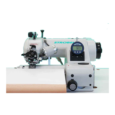
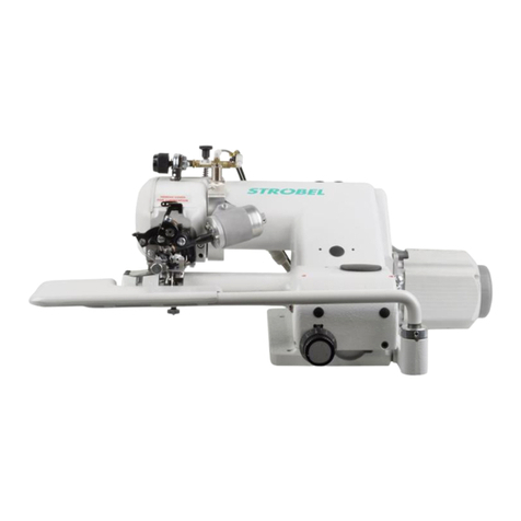
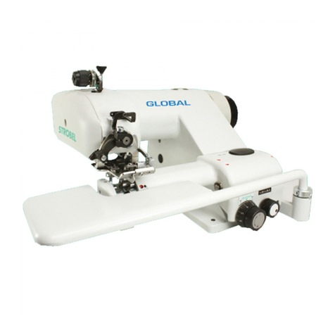
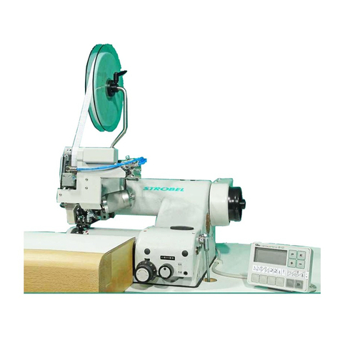
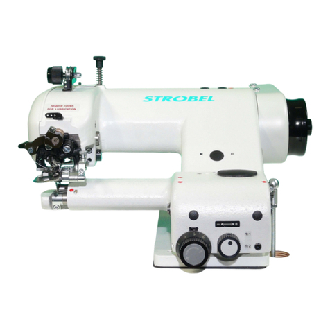
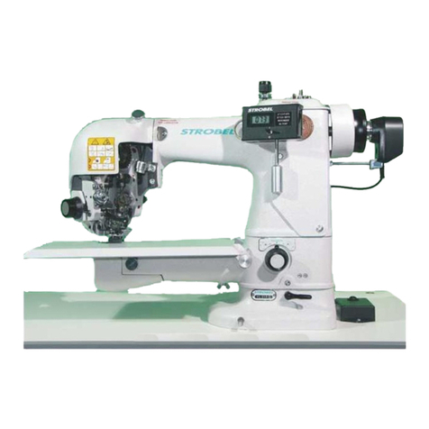
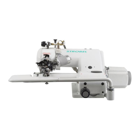
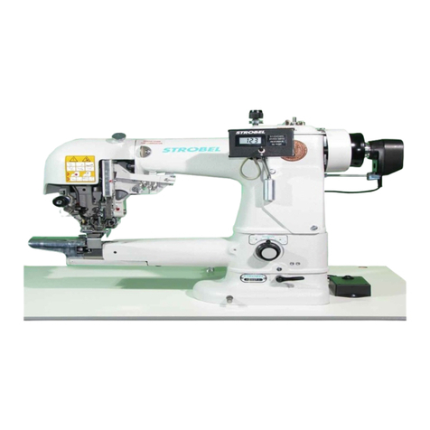
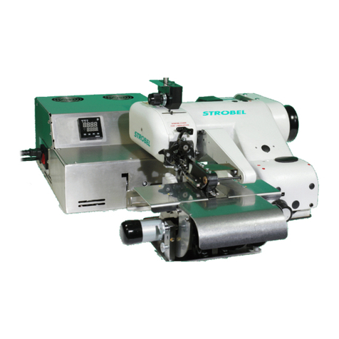
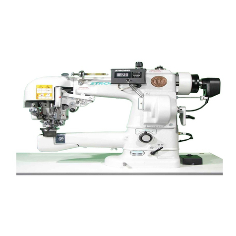
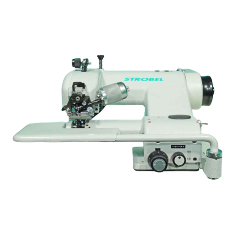
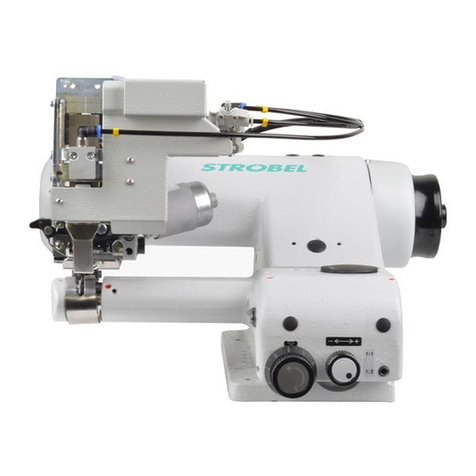
STROBEL Class VEB200-2
C o n t e n t s
1General notes on safety .............................................................................................................3
2General .......................................................................................................................................5
2.1 Operating instructions ......................................................................................................5
2.2 Class description, serial number and initial basis for description....................................5
2.3 Range of application and intended use............................................................................5
2.4 Technical data ................................................................................................................... 6
2.5 Brief setting instruction ....................................................................................................8
3Hints for repair and settings.......................................................................................................9
3.1 Mounting the stitch plate .................................................................................................9
3.1.1 Removing the stitch plate (Fig. 2).....................................................................10
3.1.2 Remounting the stitch plate (Fig. 2).................................................................10
3.1.3 Setting the stitch plate (Fig. 1)..........................................................................11
3.1.4 Replacing the needle glide plate (Fig. 3) ..........................................................11
3.1.5 Setting the cloth retainers (Fig. 4)....................................................................12
3.2 Needle lever....................................................................................................................13
3.2.1 Mounting (Fig. 5)...............................................................................................13
3.2.2 Setting the needle stroke (Fig. 7) .....................................................................14
3.3 Loop stroke (Fig. 6)..........................................................................................................16
3.3.1 Setting the loop stroke (Fig. 7) .........................................................................16
3.4 Looper .............................................................................................................................17
3.4.1 Removing and remounting the looper (Fig. 7) .................................................17
3.4.2 Removing and remounting the looper shaft (Fig. 7)........................................17
3.4.3 Looper deflection (Fig. 3)..................................................................................17
3.4.4 Setting the looper (Fig. 8) .................................................................................17
3.5 Feed dog (upper feed) (Fig. 10) ......................................................................................19
3.5.1 Setting the feed dog .........................................................................................19
3.6 Feed plates......................................................................................................................20
3.6.1 Setting the feed plates......................................................................................20
3.6.2 Setting the feed plate lifting (Fig. 10)...............................................................20
3.7 Plunger ............................................................................................................................21
3.7.1 Replacing the plunger shafts (Fig. 11) ..............................................................21
3.7.2 Setting the plunger (Fig. 12) .............................................................................22
3.7.3 Setting the cloth support arm (Fig. 11) ............................................................23
3.7.4 Setting the spring initial tension at the spring loaded plungers (Fig. 11)........23


