Strong International RADIANCE 72-00800 User manual
RADIANCE
Follow Spotlight
Type 72-00800
PRELIMINARY
STRONG INTERNATIONAL
a division of Ballantyne of Omaha, Inc.
4350 McKinley Street
Omaha, Nebraska 68112 USA
Tel 402/453-4444 • Fax 402/453-7238
www.strongint.com


RAD/001
PREFACE
THE STRONG RADIANCE SPOTLIGHT is an AC follow spot complete with
lamphouse, igniter, power supply, optical system, and color boomerang. It is available in either 1200 or
2500 watt models, and is designed for use with one of two single-ended metal halide bulbs. Bulbs are
not supplied with the unit, but are available from theatrical supply distributors.
AN ELLIPICALREFLECTOR and condenser lenses are designed to operate in a fixed
position with the bulb mounted vertically in the lamphouse. The bulb socket is adjustable in relation to
the optics to permit positioning the arc on the optical center line of the reflector and lenses. The igniter
is contained within the lamphouse enclosure.
THE SEPARATE POWER SUPPLY comes equipped with a three-wire AC line cord
and connects to a 230 volt (±10 volt), single phase 60 Hz.AC line. The 1200 watt Radiance is available
in a 115 volt model. A230 volt, 50 Hz. power supply is shipped with export models of either wattage.
The power supply is protected by a double-pole circuit breaker, and operation of the power supply is
controlled by the ON/OFF switch on the lamphouse.
THE IGNITER in the lamphouse requires a 237 V.AC open circuit pulse, provided by a
step-uptransformer in the power supply, to ignite the bulb.After ignition, the powersupply automatically
drops the voltage to the value required to maintain the arc.
ADJUSTMENT CONTROLS for positioning the metal halide bulb are located below
the bulb socket at the rear of the lamphouse. This control mechanism permits concise positioning of the
bulb in relation to the reflector and also allows the bulb to be centered both vertically and horizontally
on the optical center of the reflector.
THEPOWERSUPPLYis connected to the lamphouse by a cable assembly approximately
13 feet long, terminating in a quick-disconnect plug for easy attachment to the power supply. This
cable assembly contains all the control wires for the operation of the lamphouse and power supply.
ANINTERNALLYWIREDBLOWERisusedinthefollowspot lamphouse and operates
from the AC control circuit. This blower is used to cool both the lamphouse and optical system.
METAL HALIDE BULB (not provided with unit)
1200 Watt (G22 Base) 2500 Watt (G38 Base)
Philips MSR 1200/2 Philips MSR 2500 HR
or equivalent
RAD/002
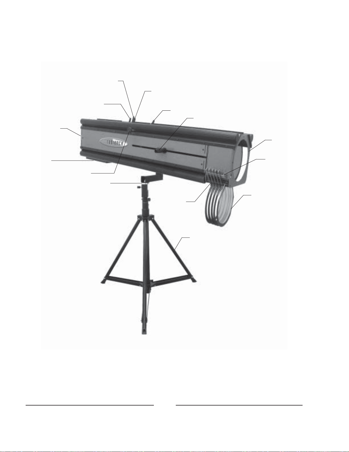
Horizontal
Masking
Shutter
Iris Vertical
Masking
Shutter
Fade-Out
Spot Size Control Handle
Color
Boomerang
Color Release
Lever
Color Frame
Color
Selector
Arm
Tripod Floor Stand
(optional)
Spigot & Cantilever Arm
Tilt Friction
Adjustment
Intake Blower,
ON/OFF Switch
(Rear Cover)
Cover, Bulb
Positioning
Screws
RAD/003
SETTING UP SPOTLIGHT
THE RADIANCE FOLLOW SPOT is shipped in sections which must be assembled.
The cantilever arm and spigot (truss pin) mount to the round tension plate on the off-operator side of
the spotlight head using (2) truss head screws. Keyhole slots in the cantilever arm align to the screws.
THE SPIGOT is a standard 28mm (1-1/8 inch) diameter for truss mounting. The spigot
will also seat into the top of the optional tripod base stand. Height of the unit may be determined by the
user, but when adjusting the tripod base, make certain the unit remains stable. Setting the tripod base
to an extreme operating height contributes to making the spotlight assembly topheavy and unsteady.
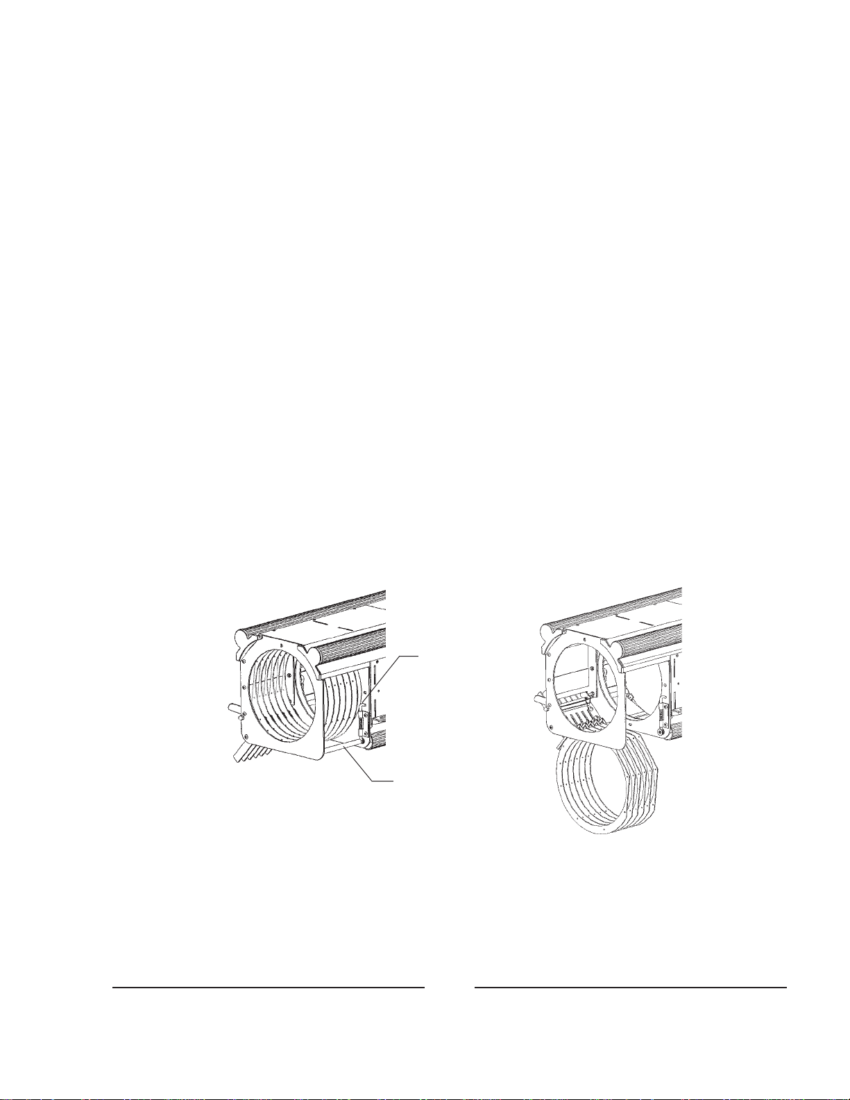
THERADIANCE COLOR BOOMERANG makesprovision for “stowing” colorframes
for shipment. When stowed, the color frames are protected from breakage or other damage caused by
transporting the spotlight. To enable operation of the color boomerang, raise the spring-loaded lockpin
and push the retainer bar into its recess. This allows the color frames to drop into a “deployed” position
for normal operation. To again stow the color frames for transport, raise all six color frames to their
engaged position, raise the lockpin, and extend the retainer bar from its recess.
CONNECTTHE CABLEASSEMBLYfrom the lamphouse to the mating receptacle on
the side of the power supply and tighten firmly. The connector and receptacle are keyed to prevent
misalignment of the pins; check for correct pin alignment before tightening the locking ring. Do not
connect the power supply to the AC line until completing the installation of the metal halide bulb.
“Stowed” “Deployed”
Lockpin
Retainer Bar

RAD/004
BULB INSTALLATION AND OPERATION
REMOVE THE REAR TOP COVER PLATE by releasing the four chromed captive
quarter-turn screws and lifting the plate from the top of the lamphouse enclosure. This will expose the
ceramic base of the two-pin bulb socket located on the base of the lamphouse between the reflector and
the condenser lenses.
THE BULB SOCKET accommodates either the 1200 (G22) or the 2500 watt (G38)
single-ended metal halide bulb. Carefully check the data plates on the spotlight head and on the power
supply to verify correct wattage before installing either bulb.
DO NOT TOUCH the quartz portion of the metal halide bulb with bare fingers! Any
fingermarks accidentally placed on the bulb envelope must be removed with alcohol before lighting
the bulb; skin oils will rapidly burn into the envelope material and shorten bulb life. Wear clean cloth
gloves or grasp the envelope using a clean cloth towel when handling the bulb.
INSERT THE METAL HALIDE BULB into the lamphouse and seat the two pins into
the bulb socket. Press firmly downward to insure correct fit and good electrical contact.
REPLACE THE TOP COVER PLATE over the lamphouse opening. Tighten all four
quarter-turn fasteners. Make certain the ON/OFF switch on the rear cover is in its OFF position.
CHECK THE POWER SUPPLYDATAPLATE for the required input voltage. Plug the
AC cord from the power supply into an appropriate AC outlet. Turn the circuit breaker on the side of
the power supply case to the “ON” position. The blowers in the power supply and in the spotlight
lamphouse will operate. Press the “ON” switch on the lamphouse and the bulb will ignite.
ALLOW THE BULB to heat up for three to five minutes to reach full brightness, then
proceed with the instructions for alignment of the bulb with the reflector. Leave the bulb on throughout
the alignment procedure; a metal halide bulb will not readily restart when hot.
USING A PHILLIPS SCREWDRIVER, rotate the three adjusting screws below the
lamphouse base pan to center and focus the bulb inside the reflector. Screw heads are accessible through
three clearance holes in the cover plate. The ideal light field is as flat as possible at highest intensity.
BOTHTHE RELFLECTORand the condenser lens assembly are positioned at the factory
for optimum light collection. Do not loosen the set screws retaining these components to the slide
rods, or otherwise reposition these elements.

RAD/005
BULB INSTALLATION AND OPERATION(continued)
WHEN TRANSPORTING THE SPOTLIGHT, or if the bulb may be subjected to a hard
shock when moving to another location, remove the metal halide bulb from the lamphouse by reversing
the installation procedures. If the control section of the bulb adjustment is not changed, the bulb should
be able to be replaced without any necessity to repeat the aligning procedures.
THE METAL HALIDE BULB ignites best when cold. After extinguishing the bulb,
allow at least thirty minutes cooling before attempting re-ignition.
EXPECTED BULB LIFE ranges from 500 to 800 hours (depending upon wattage), but
because of manufacturing tolerances, some bulbs may lose color quality before this period. Refer to
the bulb manufacturer’s specifications and information packaged with the bulb.
BULB LIFE can be maximized by avoiding repeated ignitions.Allow the lamp to burn
throughout the spotlight’s use cycle, dousing out with the masking shutter blades or fade-out mechanism
as required.
CAUTION
ULTRAVIOLET RADIATION is emitted when the bulb is ignited. Wear
protective clothing and goggles or glasses when adjusting the shutter
bladesorperforming any service with theopticalsystemhousingremoved.

RAD/006
OPERATION OF OPTICAL SYSTEM
THE SPOT SIZE CONTROL is located on the right side of the optical system protruding
from a slot in the spotlight housing. A variation of spot sizes from full flood to a small spot can be
obtained by moving the spot size control from one extreme to the other. Beam intensity is increased by
this optical system when reducing from flood to spot, and maximum intensity is reached when the spot
size control is in the extreme forward position. Depressing a thumb lever adjacent to the control
permits free movement forward and back, and releasing the thumb lever locks the control in position.
ROTATING THE CONTROLKNOB operates the spot focus control. When making an
adjustment, rotate the spot size control until the sharpest edge is obtained on the projected spot. Moving
the large lens to its center of travel and then adjusting for a sharp edge should give satisfactory results
for the full movement of the lens system.
THREE BEAM SHAPING CONTROL LEVERS are located immediately in front of
the lamphouse compartment and project through the top of the optical system housing. The iris control
is the center lever. When this lever is to the left (viewing the spotlamp from the rear), the largest
aperture is provided. Smaller apertures are obtained as the lever is moved to the right.
THE MAXIMUM FLOOD SPOT is obtained with the iris control lever to the left (away
from operating side) for the large aperture and with the spot size control moved as far as possible
toward the rear. Smaller sized spots are projected as the spot size control is moved forward. Most of
the spot sizes needed will be produced with the iris in its maximum open position.
FORA“HEAD SPOT,” or any spot size smaller than can be obtained with the spot size
control in its extreme forward position, shift the iris control lever to the right (toward operating side)
for a smaller aperture. The iris control lever should always be returned to its extreme left position
before the spot size control is again moved to obtain larger spots.
THE HORIZONTAL MASKING SHUTTER LEVER is the rearmost lever projecting
through the top of the optical system housing. The horizontal masking shutter blades are operated by
this lever to shape the projected spot to a rectangle, strip spot, or for dousing.
THE VERTICALMASKING SHUTTER LEVER is the lever in front of the iris control.
The vertical masking shutter blades are operated by this lever to narrow the projected spot from full
width to complete douse.
THE DISENGAGED POSITION of both masking shutter levers is to the extreme left
(away from operating side). Varying degrees of masking, from open to complete cutoff, are obtained
by moving the levers to the right (toward operating side).

RAD/007
OPERATION OF OPTICAL SYSTEM (continued)
THEANGLE OF THE MASKING SHUTTER BLADES can be adjusted to compensate
for the horizontal projection angle. If the spotlight is installed at an extreme house-right or house-left
position, the projected edges of the masking blades may not align horizontally with the apron, or
vertically with the proscenium. Alternately tightening and loosening the 6-32 socket head adjusting
screws (see Figure 3, Items __ and __) using a long, ball-ended 3/32" allen key will shift the position of
these blades.
THE FADE-OUT MECHANISM AND DOUSER CONTROL is the single lever
projecting through the top of the optical system housing near the center of the unit. This lever controls
the amount of light from full intensity when the lever is to the left, to complete fadeout and douse when
the lever is to the extreme right.

RAD/008
HANDLING THE SPOTLIGHT
GENERALLYTHE BEST POSITION for the operator to stand is near the center of the
spotlight, on the right hand side, although the angle of tilt and the size of porthole may alter the position
for the most convenient operation.
EACH OPERATOR will, after a few minutes of operation, generally develop his or her
own system and preferred position for operating the follow spot.
THE VERTICALTILT TENSION KNOB is located on the side of the housing adjacent
to the fade-out lever. Counterclockwise rotation of the knob frees the tilt tension, and clockwise rotation
applies tension. The individual operator can set his or her desired degree of tension.
OPERATION OF COLOR BOOMERANG
SEETHE “SETTING UPSPOTLIGHT” SECTION in the preceding pagesofthismanual
for details of the “Stowed” and “Deployed” configurations of the Radiance boomerang. It is
recommended to “stow” the color frames whenever transporting the spotlight.
THE COLOR BOOMERANG is equipped with six color filter gels containing the
following colors in order from rear to front: (1)Amber, (2) Flesh Pink, (3) Daylight Blue, (4) Light Sky
Blue, (5) Primary Blue, (6) Light Red. Keep the darkest or most dense colors (red, dark blue) to the
front of the boomerang, farthest from the bulb.
THE SIX COLOR ARMS are mounted to the side of the boomerang. To insert a color
disc in the light beam, move the proper color arm downward until the latch engages. To release a color
disc, raise the color release lever, or engage another color, thereby canceling the previous color.
TO REMOVE A COLOR DISC ASSEMBLY, release the arm and lift the color holder
ring from the arm bracket. To attach a color gel to a color frame, spray the flat surface of the ring
(without the channel clip) with an aerosol adhesive. Center the ring over a precut 12 by 12 inch (30 x
30cm) gel, and press the adhesive-coated side onto the gel. Trim the excess gel material and install the
color frame into the boomerang. Only the six above-noted colors are supplied with the boomerang;
additional colors, and color temperature reduction filters, are available from theatrical supply dealers.

RAD/009
MAINTENANCE
TO CLEAN THE CONDENSER LENSES, dismount the lamphouse top cover and
remove the bulb. Using a good grade of alcohol and piece of lens tissue (facial tissue can be used as a
substitute), gently wipe both sides of each lens until the surfaces are clean. Clean the envelope of the
bulb before replacing in the same manner.
THE REFLECTOR should be cleaned periodically with a clean, soft lint-free cloth to
remove any dust from the reflecting surface. USE NO ABRASIVES.
AREMOVABLE OPTICAL SYSTEM COVER, secured with quarter-turn fasteners, is
located immediately in front of the fade-out control lever. The center lens, and the back surface of the
large lens, can be cleaned easily through this opening.
TO CLEANTHE FRONT SURFACE of the large lens, slide the lens carriage to the full
forward position. The front surface is now readily accessible through the front of the housing.
THE INSIDE of the lamphouse and lens mechanism and the blowers should be cleaned
periodically, depending on the dust conditions at each installation. The blower blades and inlet grilles
need cleaning to remove the dust buildup that accumulates over a period of time.
THE FOLLOW SPOT does not require any lubrication.
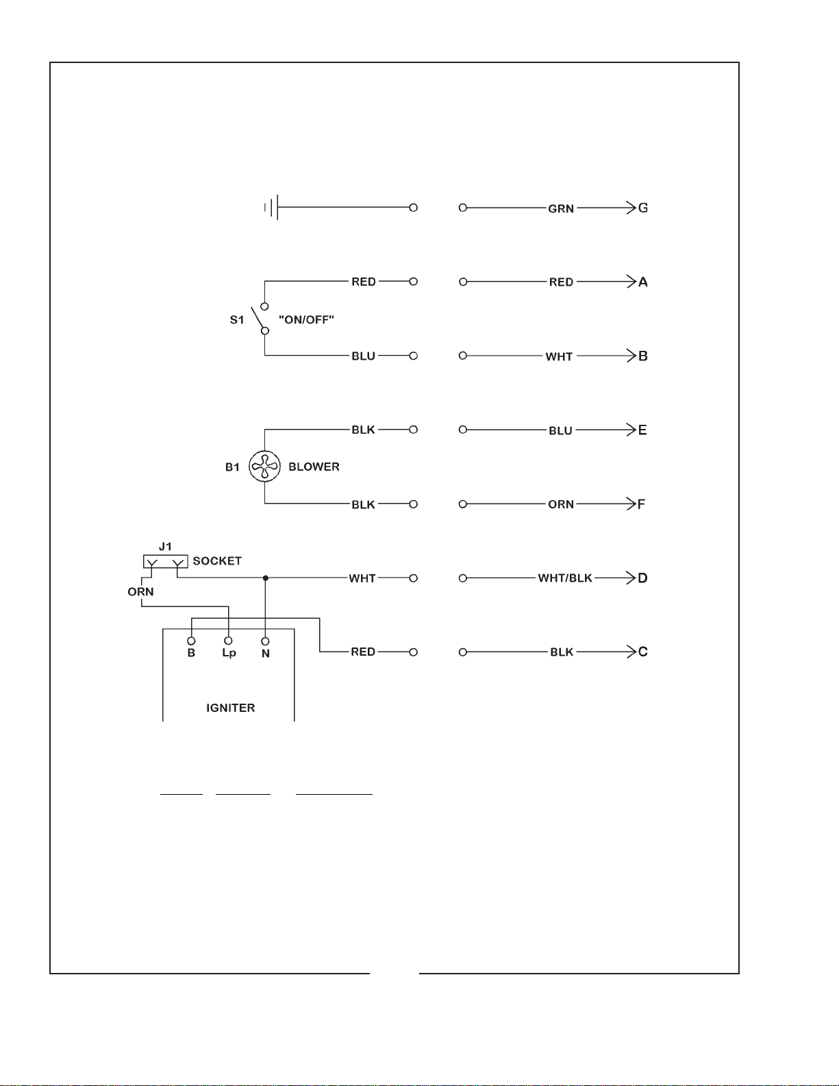
Ref.
Desig. Part No. Description
B1 71627000 Lamphouse Blower, 230 V.AC, 50/60 Hz.
J1 G22 Socket (1200 W.)
J1 71-40001 G38 Socket (2500 W.)
S1 71-61110 Rocker Switch, ON/OFF
- 71-64001 Igniter
- 71-71001 Lamphouse/Power Supply Interconnect Cable Assembly
includes (7) Pin Quick-Disconnect Plug
LAMPHOUSE SCHEMATIC DIAGRAM
575/012

575/027
RADIANCE POWER SUPPLY
2500 Watt: 72-00939

PARTS LIST
Power Supply
Item Part No. Description
1 72-00932 Cabinet Corner Extrusion (4 req’d.)
2 72-00934 Bottom Plate, Cabinet
3 72-00933 Cabinet Side Panel (2 req’d.)
4 72-00937 End Panel, Blower Mount
5 72-00938 End Cover, Louvered
6 72-00799 End Cover Bracket (8 req’d.)
7 72-00935 Top Cover Plate
8 72-00936 Transformer Mounting Bracket
9 72-00882 Extrusion Dress Plug (8 req’d.)
10 4100371 Screw, 10-32 x 3/8" Pan Head (42 req’d.)
11 4080624 Screw, 8-32 x 5/8" Pan Head (3 req’d.)
12 4060310 Screw, 6-32 x 5/16" Pan Head (7 req’d.)
13 4250508 Screw, 1/4-20 x 1/2" Pan Head (4 req’d.)
14 4258001 Hexnut, 1/4-20 Self-Locking
15 71-71002 Receptacle, (7) Pin
16 4080622 Screw, 8-32 x 5/8" Flat Head (4 req’d.)
17 4068007 Hexnut, 6-32 Self-Locking
18 71-14110 Contactor
19 71-61120 Switching Circuit Breaker, 30 A. 2 Pole
20 71627000 Blower, 230 V.AC, 50/60 Hz.
21 21-21016 Fuse, 1 A. 250 V.
22 71-64002 Transformer, 2500 Watt
22 Transformer, 1200 Watt
23 31-10001 Capacitor Clamp, 2-1/2" Diameter
24 31-08133 Capacitor, 60 µf, 370 V.AC
25 31-28039 Carry Handle
26 4100629 Screw, 10-32 x 5/8" Button Head (4 req’d.)
27 81-98254 Traction Foot, Rubber (4 req’d.)
28 4108002 Hexnut, 10-32 NyLock (4 req’d.)
29 4107101 Flatwasher, #10 SAE (4 req’d.)
30 4313000 Cap Screw, 5/16-18 x 3" Hex Head (4 req’d.)
31 4317100 Flatwasher, 5/16" (4 req’d.)
32 4318001 Nexnut, 5/16-18 (4 req’d.)
33 71307000 Blower Grille
34 31-98163 Cord Grip, Strain Relief
35 91-21001 Fuseholder


Table of contents
Other Strong International Spotlight manuals

Strong International
Strong International SUPER TROUPER II User manual

Strong International
Strong International TrussTrouper 1.2 User manual

Strong International
Strong International XENON GLADIATOR III User manual

Strong International
Strong International SUPER TROUPER II User manual

Strong International
Strong International SUPER TROUPER II User manual

Strong International
Strong International XENON GLADIATOR IV User manual

Strong International
Strong International FOLLOW SPOTLIGHT 48057 User manual


