Strong SM-RAZOR-T-M User manual

SM-RAZOR-T-M SM-RAZOR-T-L SM-RAZOR-T-XL
Strong™ Low Prole Tilt Mount
for Ultra-Thin Flat-Panel TVs
INSTALLATION MANUAL

SM-RAZOR-T Installation Manual
pg.2
www.snapav.com Support: 866.838.5052
Warnings:
Specications:
SM-RAZOR-T-M 80 lbs. (36.29 kg)
SM-RAZOR-T-L 100 lbs. (45.36 kg
SM-RAZOR-T-XL 120 lbs. (54.53 kg)
SM-RAZOR-T-M Up to VESA 400x300
SM-RAZOR-T-L Up to VESA 600x400
SM-RAZOR-T-XL Up to VESA 800x600
Maximum Flat Panel Display Weight:
Supported VESA Patterns:
CAUTION:
This wall mount is intended for use only with the maximum weight of
80 lbs. (36.29 kg) for model SM-RAZOR-T-M, 100 lbs. (45.36 kg) for
model SM-RAZOR-T-L, and 120 lbs. (54.53 kg) for model SM-RAZOR-
T-XL. Use with heavier than the maximum weight indicated may result in
instability causing possible injury.
• Installationofthisproductshouldbedonebyaqualiedprofessional.
• Donotbegininstallationbeforereviewingandunderstandingtheseinstructions.
• Ensurethemountingwallusedcansafelysupport4timesthecombinedweightof the
mount and chosen display.
• Undernocircumstancesshouldthisproductbemountedtometalstuds.
• Themanufacturerdoesnotacceptresponsibilityforincorrectinstallation.
Tools Required:
• PowerDrill
• 5/6”and3/16”DrillBit
• PhillipsHeadScrewdriver
• Level
• 3/8”SocketWrench
• Hammer
• StudFinder

© 2013 StrongTM
pg.3
SM-RAZOR-T Installation Manual
Package Contents
(Q) 17.8 x 6.5 x 1.5mm
M6 Metal Washer (x8)
(A)BlackHexwasherhead
w/PhilipsDrive
M Model (x4) L &
XL Models (x6)
(C) M4 x 12mm
PhilipsHeadScrew(x4)
(L) M8 x 16mm
PhilipsHeadScrew(x4)
L & XL Models Only
(I)M6x12mm
PhilipsHeadScrew(x4)
(F) M5 x 12mm
PhilipsHeadScrew(x4)
(G) M5 x 20mm
PhilipsHeadScrew(x4) (H)M5x30mm
PhilipsHeadScrew(x4)
(D) M4 x 20mm
PhilipsHeadScrew(x4)
(M) M8 x 20mm
PhilipsHeadScrew(x4)
M Model Only
(N) M8 x 25mm
PhilipsHeadScrew(x4)
L & XL Models Only
(O) M8 x 30mm
PhilipsHeadScrew(x4)
M Model Only
(P) M8 x 40mm
PhilipsHeadScrew(x4)
L & XL Models Only
(U) M5 x 12mm
PhilipsHeadScrew(x8)
XL Model Only
(J) M6 x 20mm
PhilipsHeadScrew(x4)
(E) M4 x 30mm
PhilipsHeadScrew(x4)
(K) M6 x 30mm
PhilipsHeadScrew(x4)
(R) 20.5 x 8.5 x 2mm
M8 Metal Washer (x8)
(S)OD13xID6x12mm
BlackNylonSpacer(x4)
(T)OD17xID8.5x12mm
BlackNylonSpacer(x4)
L & XL Models Only
Wall Plate (x1)
ExtensionBrackets(x2)
XL Model Only
DisplayBrackets(x2)
(B)ConcreteWallAnchors
M Model (x4) L &
XL Models (x6)

SM-RAZOR-T Installation Manual
pg.4
www.snapav.com Support: 866.838.5052
Installation
Step 1. Pre-Drill Wall for Mounting
A. XL Model only:IftheverticalVESA
pattern dimension on the display
is greater than 400 mm (Figure 1,
Dimension A), attach the extension
brackets to the tops of the display
brackets using the 8 included
screws (U) so the brackets will reach
between the VESA mounting holes
on the display.
B. Determinethediameterofthescrew
(parts C through P) your display
requiresbycarefullytryingtohand-
thread one screw into the threaded
insert on the rear of the display.
Ifthereisanyresistance,stop
immediately.
C. Spacers are commonly needed
on displays with curved backs or
recessed screw inserts. The screw
will thread through the appropriate
washer (Q or R), the display
brackets, any spacer needed (S or
T), and then into the display.
D. Mount the brackets so that they are as close to centered (vertically) on
the back of the display as possible. The pull rings and catch hooks face
inwardwhenmounted(Figure1).Thebracketsarelabeled“L”and“R”for
reference.
E. Ensure the brackets are installed with the flat side to the display and are
squaretoeachotherafterallscrewshavebeeninstalled(Figure1).
F. Adjust the height of the bracket release string to be above the bottom of
the display (Figure 2). Slide the clip up to lengthen and down to shorten
the release string.
Figure 1
A
XL Model Only
Figure 1
Figure 2
Lengthen
Shorten
Top of Arm
XL Model Only

© 2013 StrongTM
pg.5
SM-RAZOR-T Installation Manual
Step 2. Determine the Mounting Height of the Display
A. Attach the wall plate to the brackets on the display. Measure and record the
distance between the top of the display and the top edge of the wall plate
(Figure 3, Dimension A).
B. Markthewallwhereyouwantthetopofthedisplaytositwhenhung.
C. Subtract Dimension A from the desired mounting height on the wall to find the
correct mounting height for the top of the wall plate.
Depending on the layout of the VESA mounting holes on the display, the distance
between the wall plate and the top of the display will vary. Figure 3 illustrates the
distance that must be accounted for when deciding the final viewing height.
A
Figure 3
Top of TV

SM-RAZOR-T Installation Manual
pg.6
www.snapav.com Support: 866.838.5052
Step 3. Mount the Wall Bracket Assembly
Thewallplateisfastenedtoastudwallusingtheincludedlagscrews(A).Besureto
use the correct number of screws to fasten your mount as listed below:
Model:
SM-RAZOR-T-M:
SM-RAZOR-T-L:
SM-RAZOR-T-XL:
Number of Lag Screws:
4 (Figure 4)
4 (Figure 4)
6 (Figure 5)
Mounting on a Stud Wall
A. Pre-drillholesintotwowoodstudsusinga3/16”drillbit.Besuretodrill
intothecenterofthestudsatleast2-1/2”deep.Theuseofastudfinderis
highly recommended.
B. Insertthelagscrews(A)intoholesthroughthewallplateandtightenboltsso
thatwallplateisrmlyattached,butdonotovertighten.(Figures4and5)
Warning: Over tightening can damage the bolts, greatly reducing their holding strength.
Fig ure 5
Figure 4 Figure 5

© 2013 StrongTM
pg.7
SM-RAZOR-T Installation Manual
The wall plate is fastened to a concrete wall using the included lag screws (A) and
wallanchors(B).Besuretousethecorrectnumberofscrewsandanchorstofasten
your mount as listed below:
• Verifythatyouhaveaminimumof1-3/8”ofconcretethicknesstobeusedfor
the concrete anchors.
• Donotdrillintomortarjoints!Besuretomountinasolidpartoftheblock,
generally1”minimumfromthesideoftheblock.
• CinderblockmustmeetASTMC-90specifications.
• Toavoidbreakingoutthebackoftheholewhenenteringavoidorcavity,itis
suggested that a standard electric drill on slow setting is used to drill the hole
instead of a hammer drill.
• Concretemustbe2000psidensityminimum.Lighterdensityconcretemay
not hold anchors.
• Makesurethatthesupportingsurfacewillsafelysupportthecombinedload
oftheequipmentandallattachedhardwareandcomponents.
Mounting on a Concrete Wall
Warning: When installing wall bracket on cinder block:
Model:
SM-RAZOR-T-M:
SM-RAZOR-T-L:
SM-RAZOR-T-XL:
Number of Lag Screws:
4 (Figure 4)
6 (Figure 5)
6 (Figure 5)
A. Pre-drillholesintoconcreteusing5/16”
drillbitstoadepthof21/2”.Insert
concretewallanchors(B)andtapinwith
hammer if necessary (Figures 6 & 7).
B. Insertthelagscrews(A)intothewall
anchors(B)throughthewallplateand
tighten all bolts so that wall plate is
firmly attached, but do not over tighten.
Warning: Over tightening can damage the
bolts, greatly reducing their holding strength.
Correct
concrete
concrete
plaster/
drywall
plaster/
drywall
Incorrect
Cutaway View
Figure 2
Fig ure 6
Figure 6
Cutaway View
IncorrectCorrect
Drill holes and
insert anchors.
Place wall arm
assembly plate
over anchor and
secure with lag screw.
Tighten all
lag screws.
Concrete
Wall
Wall Arm
FlangeBolt
Figure 7
Figure 4

SM-RAZOR-T Installation Manual
pg.8
www.snapav.com Support: 866.838.5052
Step 4. Hang Display onto the Wall Plate
A. Carefully lift the display and place the bracket hooks over and onto the angled
lip in the wall plate (Figure 8). Do not release the display until it is completely
connected to the wall plate.
B. Pullthereleasestringsdownonbothsidesofthedisplay,andgentlypresson
the bottom of the display to lock the brackets onto the wall plate. (Figure 9)
C. Let the release strings slide back up, and check to see that the catches engage
by gently pulling the bottom of the display.
Afterthemountisinstalled,thedisplaycanbeconnectedtothewiring.Then,nallevel
and tilt adjustments can be made. See the the following sections for more details.
Figure 8
Installing Locked
Figure 9

© 2013 StrongTM
pg.9
SM-RAZOR-T Installation Manual
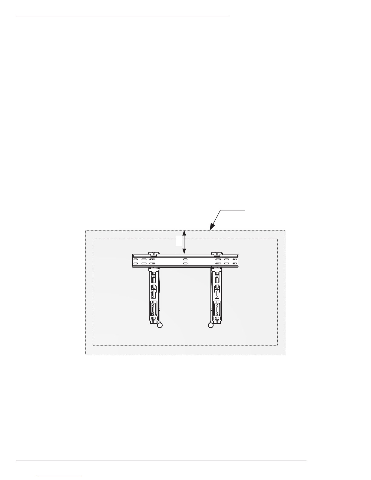
Wire Management Kickstands
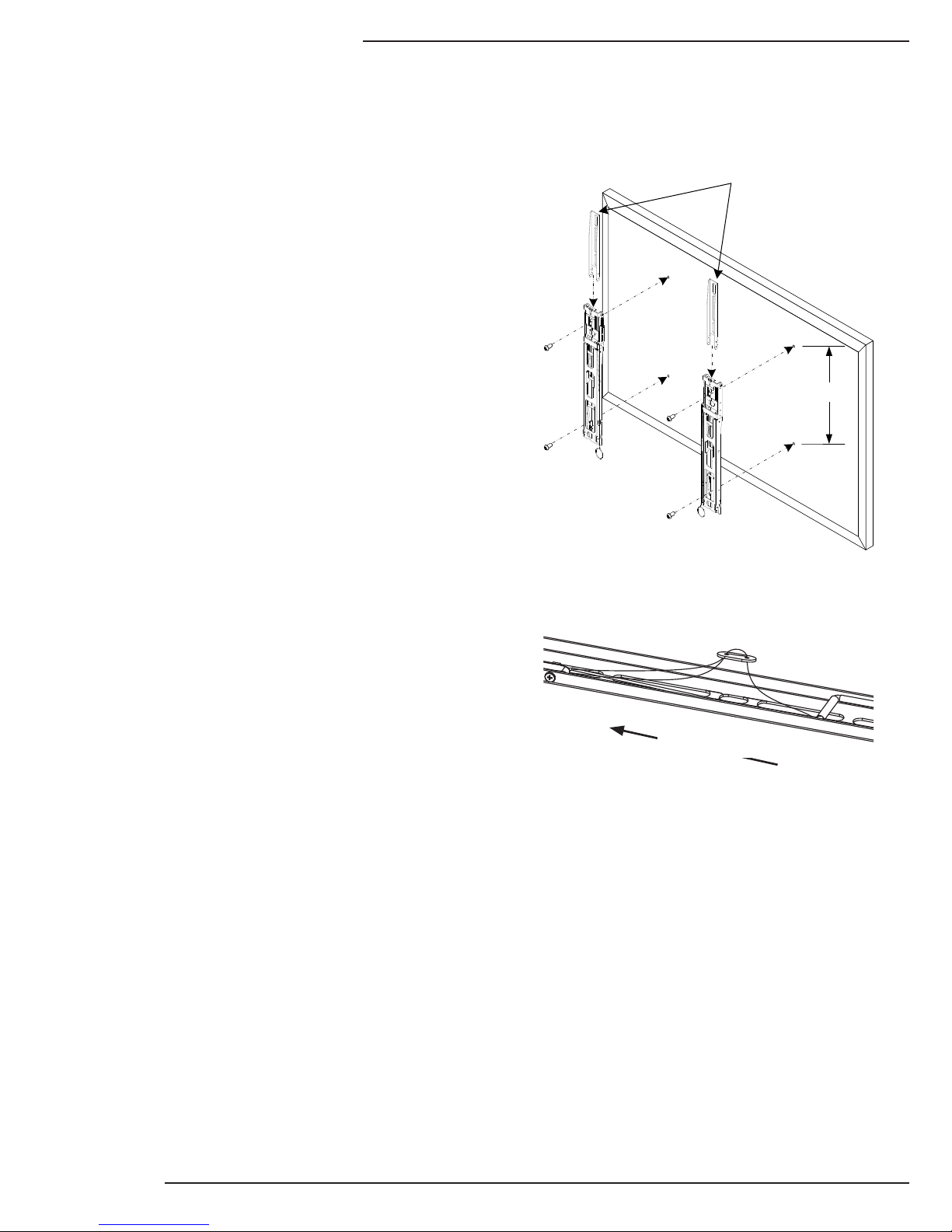
Display Leveling Adjustment
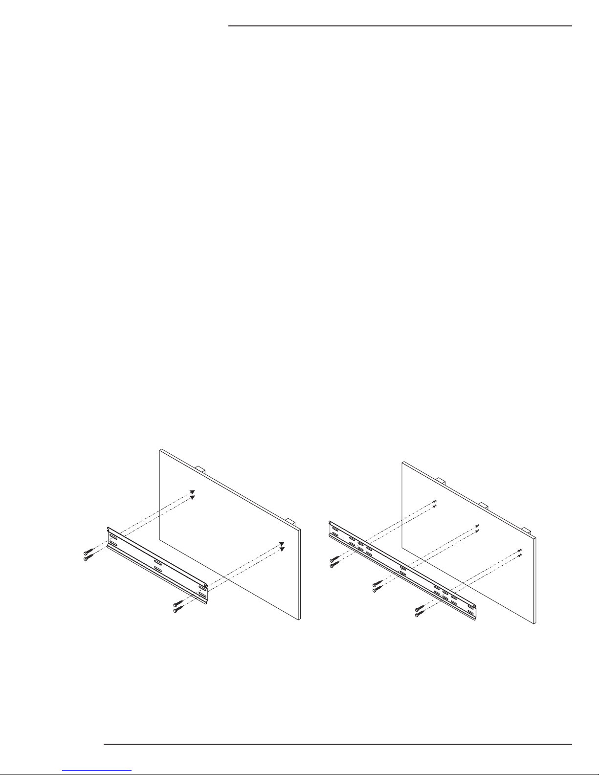
TheSM-RAZOR-Tmountsareequippedwithakickstandthatprovidesspacebetween
the display and the wall for connecting or disconnecting cabling
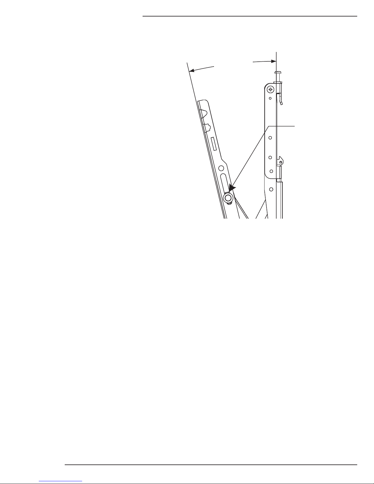
After mounting, the display may not be
hanging perfectly level. The set screw
at the top of each mounting hook allows
either side to be adjusted using a Phillips
screwdriver (Figure 11).
Place a level on one side of the display
as the adjustment is made. Turn the
screw clockwise to raise a side, or
counterclockwise to lower a side, until the
display is level.
Warning: Turning the leveling adjustment screws
too far clockwise to raise the display height could
lock the display brackets to the wall plate. This
could cause damage to the display or the mount
when trying to disconnect the display brackets from
the wall plate.
Note: These kickstands are provided for servicing only, it is recommended that they are
collapsed and the brackets are locked during normal placement.
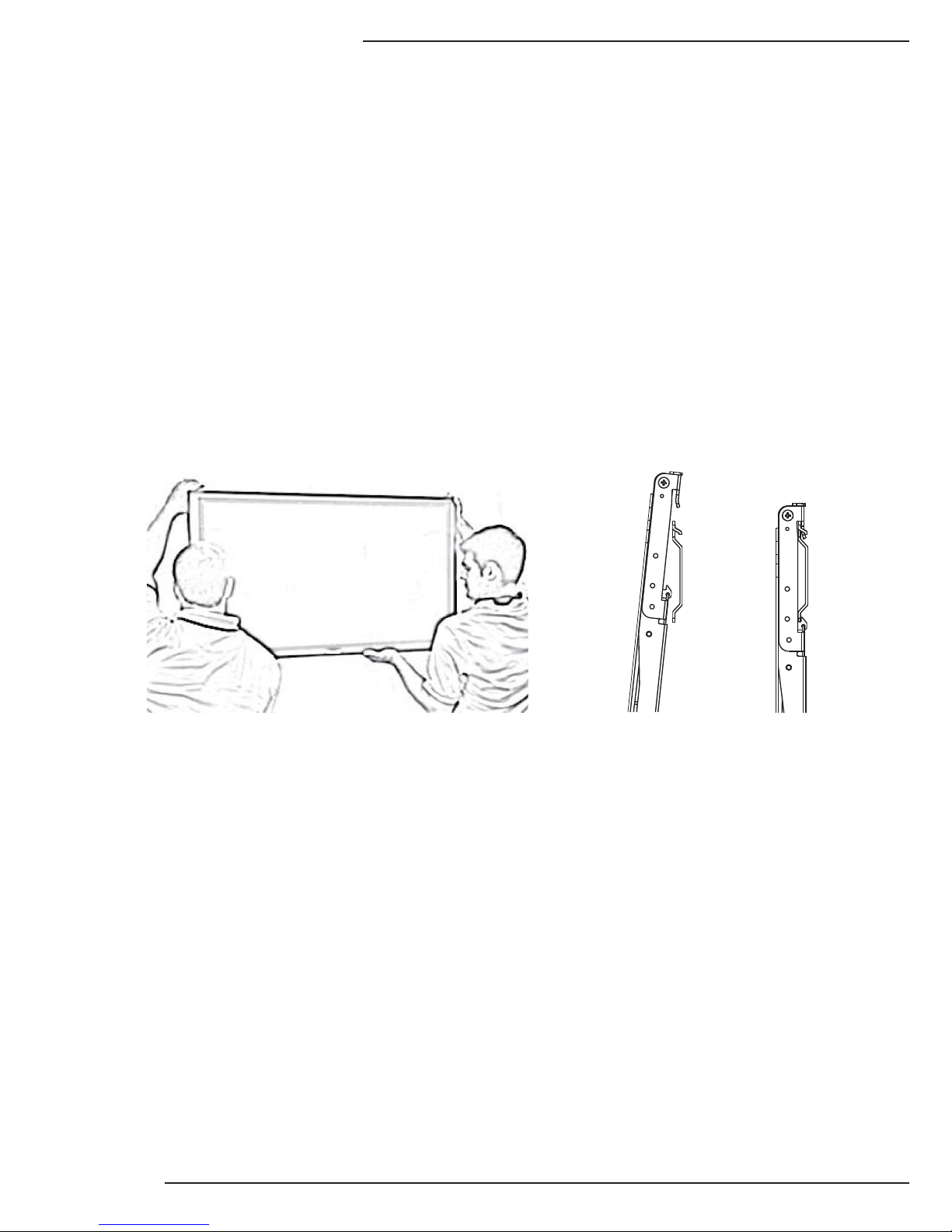
A. Pull down on the rings at the
bottom of the brackets to release
them from the wall bracket.
B. Pullthekickstandsoutoneach
bracket so that they rest on the
wall. (Figure 10)
C. When finished, collapse the
kickstands to allow the brackets
to lock onto the wall bracket.
D. Let the release strings slide
back up, and check to see that
the catches engage by gently
pulling the bottom of the display.
Figure 10
Leveling
Adjustment Screws
Figure 11

SM-RAZOR-T Installation Manual
pg.10
www.snapav.com Support: 866.838.5052
Display Tilt Adjustment
The SM-RAZOR-T mounts offer up to
15° of downward tilt. The mount is flat
(0°) when pushed to the wall. Once
the display is moved out, it tilts to 5°
and then can be adjusted from 5-15°.
To adjust the viewing angle of the
display, carefully push or pull the top
of the display toward or away from the
wall (Figure 13). The mount will snap
into place when pushed flat to the wall.
Ifthedisplaycannotbeadjustedwith
ease, loosen the tilt set screws until
the proper feel is achieved using a
Phillips screwdriver (Figure 12).
Ifthedisplaysagsafterbeingset,tightenthetiltsetscrewsuntilnosaggingoccurs.
The total adjustment needed should be minimal, no more than ¼ turn tighter or looser
than the default setting.
Warning: Do NOT over-loosen or remove the tilt adjustment friction screws. Doing so may cause
permanent damage to the mount or display.
Tilt Set Screw
Max 15°
Figure 12

© 2013 StrongTM
pg.11
SM-RAZOR-T Installation Manual
Lifetime Limited Warranty
Strong™ Mounts have a Lifetime Limited Warranty. This warranty
includes parts and labor repairs on all components found to be
defective in material or workmanship under normal conditions of use.
This warranty shall not apply to products which have been abused,
modified or disassembled. Products to be repaired under this warranty
must be returned to Snap AV or a designated service center with prior
notification and an assigned return authorization number (RA).
Lifetime
Contacting Technical Support
Phone: (866) 838-5052
Email: Techsupport@snapav.com

© 2013 STRONG™
130410-1510
This manual suits for next models
2
Table of contents
Other Strong TV Mount manuals