Strong Razor Articulating VersaMount... User manual

SM-VM-ART1-IW-16-L
Strong™ Razor Series Articulating VersaMount™
INSTALLATION MANUAL
SM-VM-ART1-IW-16-L

Pg. 2

Pg. 3
HARDWARE
#IMAGE DESCRIPTION ITEM QTY
BAG 1 Enclosure Mounting Screw (A) 6 × 40 mm 7
Concrete Anchor (B) 8 × 40 mm 7
Screw (C) M6 × 20 mm 4
Screw (D) M6 × 40 mm 4
Screw (E) M8 × 20 mm 4
Screw (F) M8 × 40 mm 4
BAG 2 Screw (G) M8 × 50 mm 4
Spacer (H) 8.5 × 15 × 5 mm 4
Spacer (I) 8.5 × 17.5 × 10 mm 4
Spacer (J) 8.5 × 17.5 × 19 mm 4
Spacer (K) 8.5 × 17.5 × 22 mm 4
BAG 3 M6 Washer (L) 6.4 × 18 × 2 mm 8
M8 Washer (M) 8.4 × 20 × 2 mm 8
Screw (for bezels) (N) M3 × 5 mm 8
Screw (for adapters) (O) M8 × 10 mm 8
M6 Lock Nut (for TV plate) (P) M6 2
M6 Washer (for TV plate) (Q) 6.4 × 16 × 1.5 mm 2
Nylon Washer (for TV plate) (R) 6.5 × 16 × 1.5 mm 2
BAG 4 10mm Socket Wrench 1
Wrench 1
Velcro Strips 4
Additional Tools Required
• Power Drill with
• 1/4” Drill Bit
• #2 Phillips Screwdriver
• Level
• 10mm Socket Wrench
• Stud Finder (for wood stud mount)
• Wood shims (optional)
• 5/16” drill bit
• Hammer
• Nails or tape (for drywall cutouts)
• Drywall saw (for drywall cutouts)

Pg. 4
1. WARNINGS
• These wall mounts are intended for use only with the maximum weight capacities listed below.
• Installationbyaqualiedprofessionalishighlyrecommendedforthisproduct.
• Do not begin installation until you thoroughly read and understanding these instructions.
• Ensure the mounting wall will safely support four times the combined weight of the mount and display panel.
• The manufacturer does not accept responsibility for incorrect installation.
CAUTION:
Use with heavier than the maximum weight indicated may result in instability which could possibly cause injury.
1. AVERTISSEMENTS
• Ces supports muraux sont pour être utilisés seulement avec les capacités de poids maximales ci-dessous.
• L’installationparunprofessionnelqualiéestfortementrecommandéepourceproduit.
• Ne commencez pas l’installation avant d’avoir lu et compris ces instructions.
• Assurez-vous que le mur de montage supporte en toute sécurité quatre fois le poids total du support et du panneau
d’achage.
• Le fabricant n’accepte pas la responsabilité por une installation incorrecte.
MISE EN GARDE:
Une utilisation avec un poids plus haut que le poids maximal indiqué peut provoquer une instabilité et ainsi des
blessures.
CAUTION: This wall mount is intended for use only with a maximum display weight of 100 lb / 45 kg.
Preparing an Existing Wood Stud Wall (Retrofit with Drywall)
The VersaMount ts a 16" stud bay. Under no circumstances should you mount this product to metal studs.
WARNING: Studs must be a minimum of 2"×4" and covered with no more than 3/8" thick drywall.
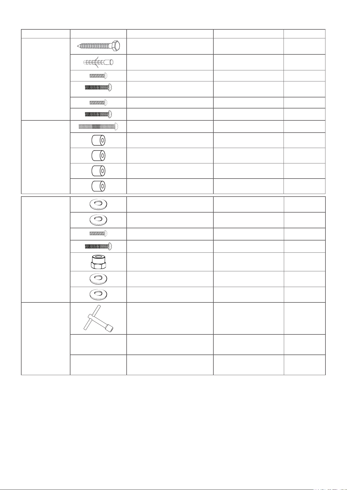
Materials required:
- Stud Finder - Cutout Template - Tape or Nails and Hammer - Drill - Drywall Saw
• Locate and mark the edges of the stud bay in the mount location.
• Using tape or nails, secure the provided cutout template in the desired mount location. Use the marks you made to
orient the template properly.
• Using a drill, make holes along the cutout line every 4–6 inches.
• Remove the template and complete the cuts using a drywall saw. Remove the drywall.
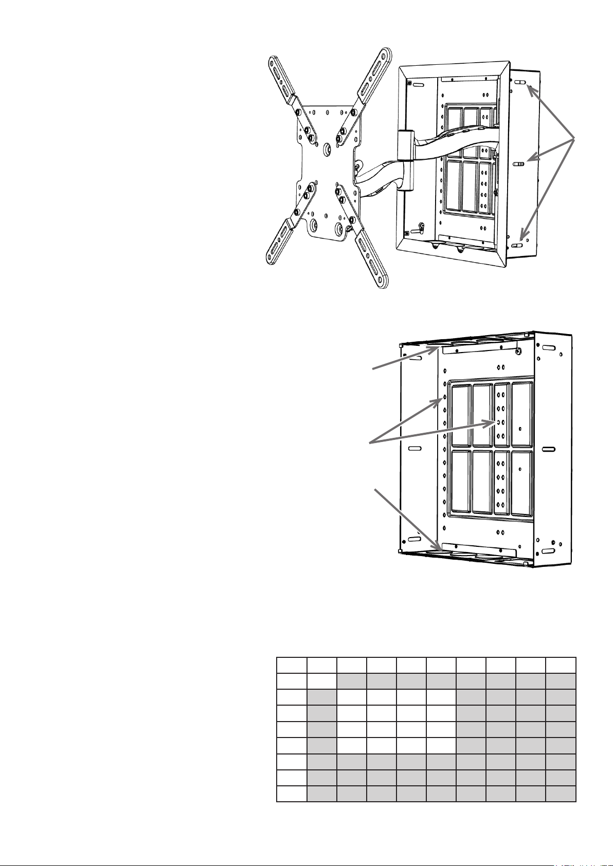
2. Installing the Enclosure into the Wall
Materials required:
- Wood Shims
- 6 × Lag Bolts (A)
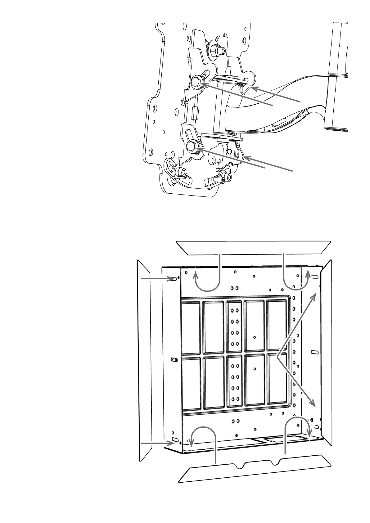
2.1 Reverse the Track Position
(OPTIONAL)
The vertical track and arm come pre-installed at
the right side of the enclosure. If your job requires
that the arm be at the left side of the box, remove
the twelve bolts (the nuts for which are shown to
the right), remove the arm, rotate the enclosure
180°, and use the bolts to re-install the arm.

Pg. 5
2.2 Inserting and Securing the Enclosure into the Wall
• Insert the enclosure into the wall.
• Shim the sides as needed so the enclosure
does not deform when securing the side walls.
Insert the lag bolts (A) into the outer holes
at the sides of the enclosure to secure the
enclosure to the wood studs.
3. Installing Equipment into the Strong VersaMount
The VersaMount allows for a variety of equipment
congurationoptions.Experimentwiththeequipment
congurationtodeterminethebestinstallationmethod.
Forimagesofdierentcongurationsofequipment
installed in the VersaMount, see the VersaMount product
page and Support Tab at SnapAV.com.
3.1 Using Knockouts
The knockouts on the top and bottom can hold low-
voltage rings or outlet boxes. An outlet box must be an
old-work metal junction box with integrated supports
forsecuremounting;new-workplasticoutletsdonott.
3.2 Modules
The back wall of the enclosure has holes and knockouts
on 6” centers to allow for easy structured can module
installation. Use a 1/4” drill bit to open more of the
knockout stamps as needed to mount equipment.
4. Install the Display Adapter Plate
This mount is compatible with most VESA patterns
between 75×75 and 400×400. Some VESA
patterns require the use of the included display
adapter brackets. The table at right shows whether
your display requires adapter brackets: standard
VESA patterns are shown in white. Patterns with
check marks can use the base plate (proceed to
step 6.2); VESA patterns with double diamonds
require the use of adapters (proceed with step 6.1).
knockout
knockout
module
holes
75 100 200 300 400 500 600 700 800
75 P
100 P P ³ ³
200 P P ³ ³
300 ³ ³ ³ ³
400 ³ ³ ³ ³
500
600
700
mount arm not shown for clarity

Pg. 6
4.1 Attaching the Display Adapter Brackets
To attach the extension adapters, align the adapter bracket holes with those on the TV-facing side of the adapter plate
and secure in place with the included bolts (O). The display adapter brackets can reach VESA patterns up to 400×400
andprovideadditionalexibilitywhenneeded.Referencetheexamplesbelowforsomewaystheadapterbrackets
can be used to achieve various VESA patterns.
Warning: Over-tightening can damage the bolts or the display and is not covered under warranty. Make sure the
fasteners are tight enough not to rattle loose while the mount is in use.
4.2 Attaching the Display
• Carefully lay the display face-down on a soft surface.
• Locate the four mounting holes in the back of the display housing. Carefully test threading the screws (C through G)
intothebackofthedisplayuntilyoundtheproperthread.
• Lay the adapter plate centered over the display with the two roll adjustment screws toward the bottom of the display.
Ensure the mounting holes of the display match up properly to four of the holes in the adapter plate.
• ChecktheclearancebetweentheTVandtheplate.Iftheplatewon’tsitatagainstthebackofthetelevision,place
spacers (H through K) and washers (L or M) between the display and the plate as needed.
• Fasten the plate to the display. Use screws long enough to thread securely into the display without bottoming out.
Warning: Over-tightening can damage the bolts or the display and is not covered under warranty. Make sure the
fasteners are tight enough not to rattle loose while the mount is in use.
5. Attach the Display to the Arm Asembly
• Lift the display and place the bolt at the center of
the plate into the notch as shown. Once placed,
the two bolts at the bottom will swing into place
through the level adjustment slots.
• Secure the display using the two Nylon washers
(R), two metal washers (Q), and lock nuts (P).
Be sure to place the Nylon washer between the
mount and the metal washer. This will allow for
easier tilt adjustments later.
• Secure the nuts with the 10mm socket wrench.
400×400 400×200 400×100
R QP

Pg. 7
6. Adjusting Display Position
6.1 Horizontal Level Adjustments
• You tightened the locking nuts at the bottom of the arm assembly end plate
at the end of the last step. Now loosen them ¼ turn each. This allows you
topositionthedisplaywithminimaleort.
• Place a level on top of the display, and rotate the display until it is horizontally
level.
• After adjustment is complete, tighten the nuts.
6.2 Vertical Position Adjustments
WARNING: Loosen the vertical shift lock bolts before adjusting the vertical position. Using vertical shift while
lock screws are engaged will damage the height adjustment system.
• Locate the four locking bolts on the sides of the vertical track . Loosen these bolts so the sled can move up and
down. There are two on each side, all four must be disengaged before adjusting height. They do not need to be
removed.
WARNING: Do not over-drive the height adjustment to its extremes (top or bottom). Doing so will damage the
height adjustment system.
• Locate gear box and
10mm hex gear drive
toward the bottom of
vertical track.
• Use a drill with 10mm hex
socket or provided socket
wrench to adjust. Use
the drill at low speeds
to ensure you do not
damage the system.
• Turn bolt clockwise to
move mount down.
• Turn bolt counter-
clockwise to move
mount up.
• Once the height is where
you want it, tighten the
locking bolts to secure
the display.
+/- 4°
leveling nuts
+/- 10°

Pg. 8
6.3 Tilt Adjustments
Tilt adjustments usually do not require
loosening any bolts or screws. The tilt
plate fasteners have been pre-adjusted for
easy adjustment with most TVs. However,
heavier TVs may sag due to the extra
weight.
Manually adjust the display to your
preferred angle, then evenly tighten the
lock nuts on each side of the arms using
the 10mm socket wrench to prevent the
display from sagging.
7. Attach Bezel
Attach the four pieces of the bezel
by securing the tabs on the rear
of reach piece to the inside of the
enclosure. Each bezel piece is
secured by two screws (N).

Pg. 9
8. Dimensions
All measurements in inches.
15.55
13.27
17.05
14.76
7.87
7.87
15.75
15.75
17.05
15.55
3.97
14.25
15.83
15.66
16.08
19.64
20.06

Pg. 10
Copyright ©2021, Wirepath Home Systems, LLC. All rights reserved. Control4 and SnapAV and their respective logos are
registered trademarks or trademarks of Wirepath Home Systems, LLC, dba “Control4” and/or dba “SnapAV” in the United States
and/or other countries. Control4, Snap AV, Strong, Strong Versabox, and WattBox are also registered trademarks or trademarks
of Wirepath Home Systems, LLC. Other names and brands may be claimed as the property of their respective owners. All
specicationssubjecttochangewithoutnotice.
Warranty
Limited Lifetime Warranty
Find details of this product’s Lifetime Limited Warranty at snapav.com/warranty, or request a paper copy from Customer Service
at (866) 424-4489. Find other legal resources, such as regulatory notices and patent information, at snapav.com/legal.
Lifetime
Contacting Technical Support
Phone: (866) 838-5052 Email: Techsupport@snapav.com
©2021 Strong™
210325-1542
Part # 200-SM-VM-002
This manual suits for next models
1
Table of contents
Other Strong TV Mount manuals