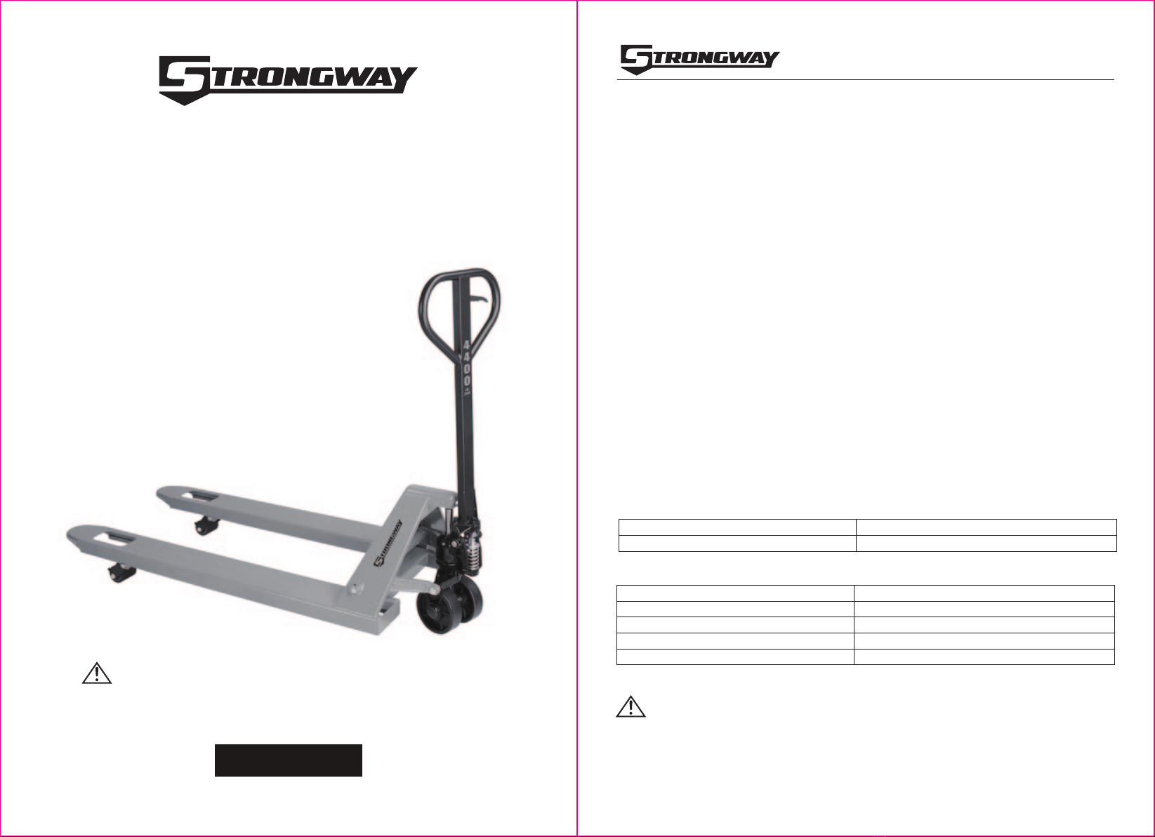
4400-Lb. Capacity Pallet Jack
OWNER’S MANUAL
Operating Instructions
WARNING:
• To avoid serious bodily injury or death, and/or property damage, do not exceed the rated
load capacity.
• When not in use, do not allow heavy loads to remain on the fork for an extended period of
time. Always lower the fork completely when not in use.
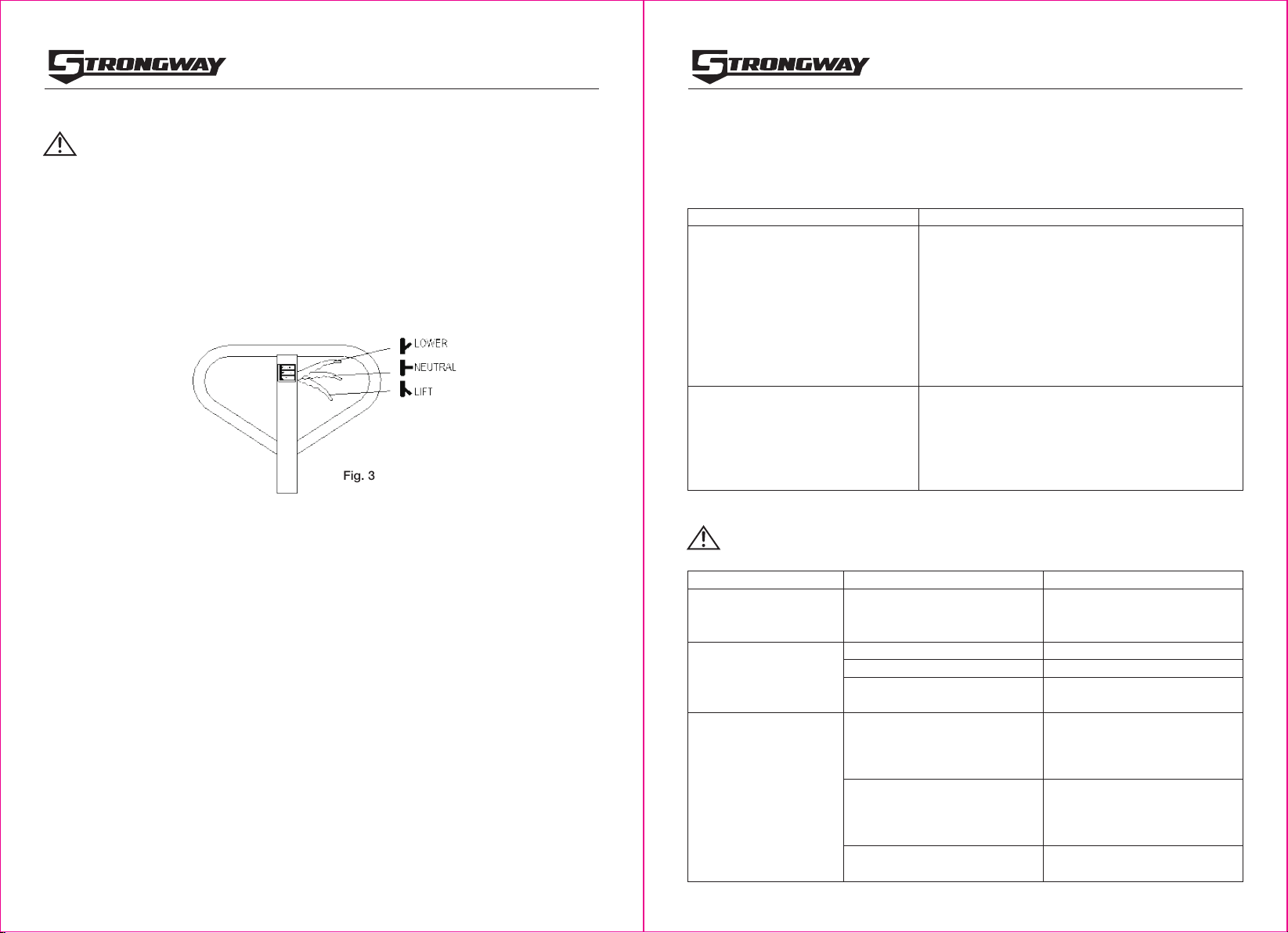
Adjusting the Control Handle – 3 Positions
On the drawbar of this pallet jack, you can find the control handle (117N) which allows for three
positions (Fig. 3):
LOWER - To lower the load, pull up on the control lever.
NEUTRAL - Place the control lever in this position while pulling the pallet jack or load.
LIFT - To raise the load, push down on the control lever and pump the handle to raise the
load.
Note: These three positions have been set at the factory to work as soon as the handle is
attached. However, if the forks do not raise or lower as expected, adjust the control positions
using the following instructions:
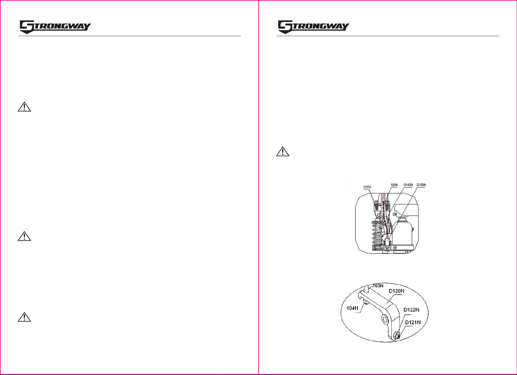
1. The adjusting screw (D121N) (Fig.2) is designed to adjust the 3 control positions. Use a
wrench and a slotted screw driver to loosen the nut and turn the adjusting screw clockwise,
or counter-clockwise, in order to leave 4-5 threads out after the nut is secured on the lever
plate (D120N). Check to see if the pallet jack works correctly in the 3 control positions. If
more adjustments are necessary, proceed to the following steps.
2. Place the control handle in the NEUTRAL position. If the fork frame does not rise when you
pump the pallet jack, skip to step 5. If the fork frame does rise when you pump the pallet
jack, turn the adjusting screw CLOCKWISE until the fork frame does not rise.
3. Keep the control handle in the NEUTRAL position. If the fork frame does not move when the
handle is pumped, skip to step 4 without any adjustment. If the fork frame lowers, turn the
adjusting screw COUNTER-CLOCKWISE until the fork frame does not lower.
4. Pull the control handle upward to the LOWER position. If the fork frame lowers, skip to step 5
without any adjustment. If the fork frame does not lower, turn the adjusting screw
CLOCKWISE again until the fork frame lowers.
5. Push the control handle down to the LIFT position. If the fork frame (D214N) elevates when
you pump the pallet jack, go back to check steps 1 to 3 until the pallet jack can work well in
all 3 control positions. If the fork frame does not elevate, turn the adjusting screw
COUNTER-CLOCKWISE again until the fork frame elevates. Repeat steps 1 thru 3 until the
pallet jack works in all 3 control positions.
4 of 11
4400-Lb. Capacity Pallet Jack
OWNER’S MANUAL
5 of 11
Fig. 3
Maintenance
Maintain the product by adopting a program of conscientious repair and maintenance in
accordance with the following recommended procedures. It is recommended that the general
condition of any tool be examined before it is used. Keep your tool in good repair. Keep handles
dry, clean, and free from oil and grease. The following chart is based on a normal operation
schedule.
Troubleshooting
WARNING:
Do not attempt to repair the pallet jack unless you are trained and authorized to do so.
Maintenance Interval Maintenance Point
Daily before operating
Daily inspection and maintenance of the pallet jack is
required, especially for the wheels and the axles.
Remove thread or rags on the wheel or axle if any are
detected. Unload and lower the forks to the lowest
position after every job is finished.
Use motor oil or grease to lubricate all movable parts.
Remove the air by moving the control handle to the
LOWER position, then pump the handle up and down
several times. Repeat this process until the forks lift
as intended.
After every 6 months operating
Failure Possible Cause Corrective Action
The forks cannot be
raised up to the
maximum height.
There is not enough hydraulic
oil in the pump. Add more oil.
Check the oil level every six months. The oil can be
hydraulic oil, motor oil, or break oil.
The pump capacity is about 14.37 oz. (0.425 liters).
When changing or adding oil, fill the tank through
the oil plug hole with 7.78 oz. (0.23L) of new
hydraulic jack oil.
The forks cannot be
raised.
Missing hydraulic oil.
The oil has impurities.
Air has been introduced into
the hydraulic oil.
Fill with oil.
Change the oil.
Bleed the air.
The forks cannot be
lowered.
The piston rod (D135N) or pump
body is deformed, resulting from
a partial load slanting to one
side or overloading.
The fork was kept in the high
position for a long time with the
piston rod exposed, causing
rusting and jamming of the rod.
The adjusting screw (D121N) is
not in the correct position.
Replace the piston rod (D135N)
or pump body.
Keep the fork in the lowest
position when not in use.
Ensure the rod is properly
lubricated.
Adjust the screw (D121N). See page
9 for adjusting the control handle.