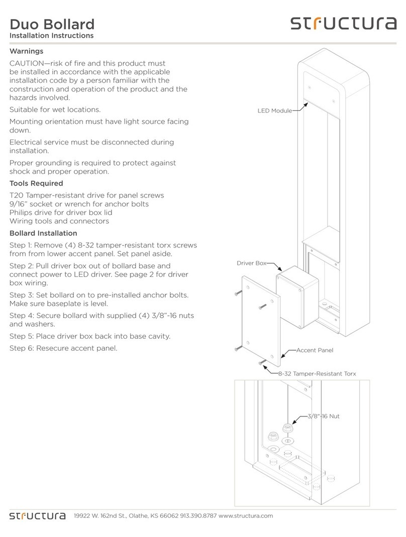
structura Mac User manual
Other structura Landscape Lighting manuals
Popular Landscape Lighting manuals by other brands
AMP Lighting
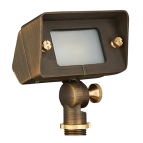
AMP Lighting AFL-4010-4-B-BZ Installation & maintenance guide
LIGMAN
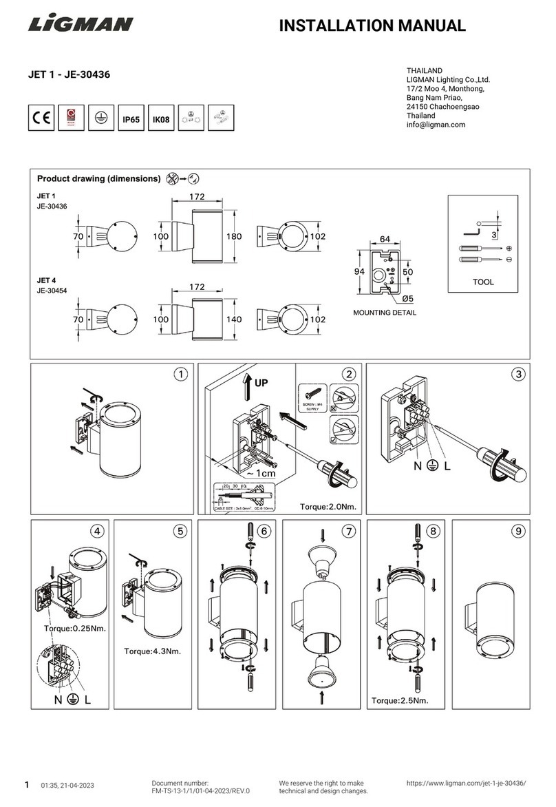
LIGMAN JET 1 installation manual
Cooper Lighting
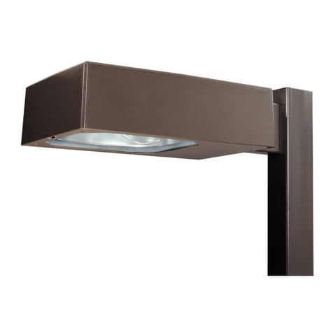
Cooper Lighting Tribute brochure
AMP Lighting
AMP Lighting TuscanPro APL-3026-4-B-BZ Installation & maintenance guide
Volt
Volt VPL-1002 Series installation instructions
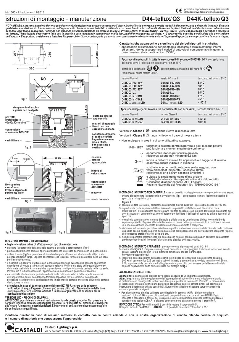
Castaldi Lighting
Castaldi Lighting D44K/Q3-L Series Installation and maintenance sheet
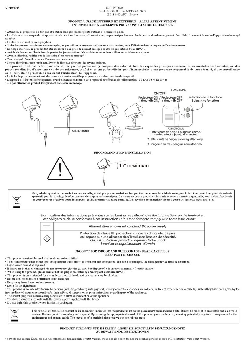
BLACHERE ILLUMINATIONS
BLACHERE ILLUMINATIONS PRD022 quick start guide
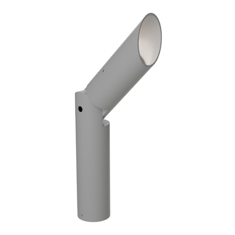
B-K lighting
B-K lighting ArtiStar Series quick start guide

Volt
Volt RGBW BuddyPro VHS-6725-0-BRB installation instructions
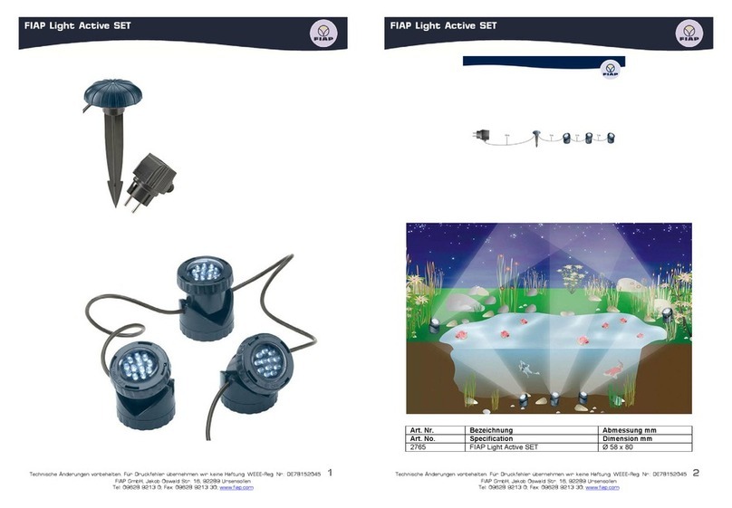
Fiap
Fiap 2765 operating manual
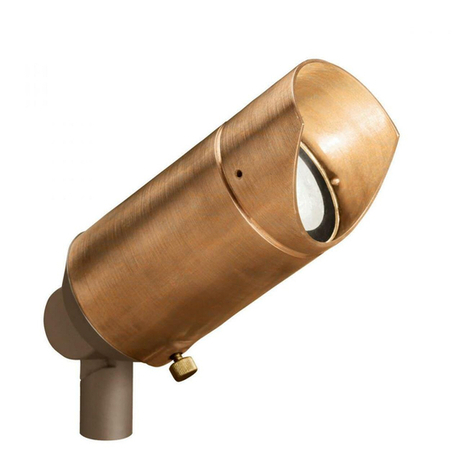
Kichler Lighting
Kichler Lighting 15384CO instructions
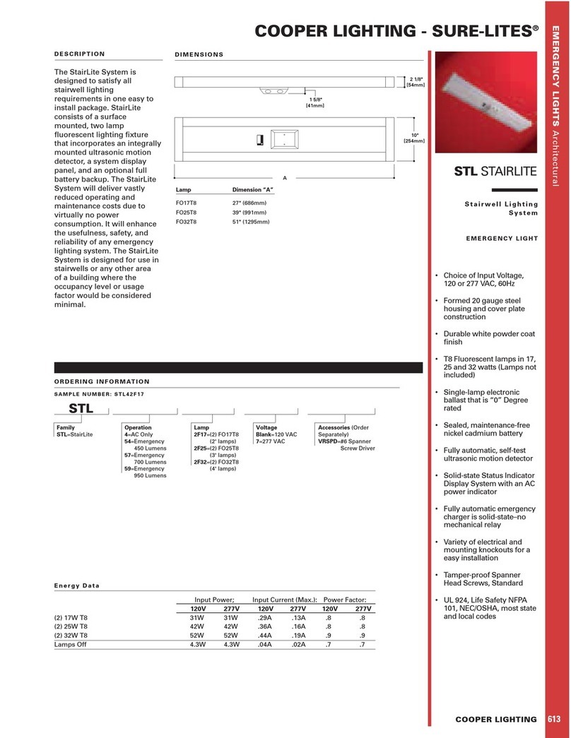
Cooper Lighting
Cooper Lighting Sure-Lites STL StairLite Specification sheet


