Struers AbraPol-10 User manual

Manual No.: 15097001
Date of Release 15.06.2005
AbraPol-10
Instruction Manual


AbraPol-10
Instruction Manual
Table of Contents Page
User’s Guide ..............................................................1
Reference Guide.......................................................31
Quick Reference Guide............................................63
A
lways state Serial No and Voltage/frequency if you have technical questions or when ordering spare parts.
You will find the Serial No. and Voltage on the type plate of the machine itself. We may also need the Date
and Article No of the manual. This information is found on the front cover.
The following restrictions should be observed, as violation of the restrictions may cause cancellation of
Struers legal obligations:
Instruction Manuals: Struers Instruction Manual may only be used in connection with Struers equipment
covered by the Instruction Manual.
Service Manuals: Struers Service Manual may only be used by a trained technician authorised by Struers.
The Service Manual may only be used in connection with Struers equipment covered by the Service Manual.
Struers assumes no responsibility for errors in the manual text/illustrations. The information in this manual is
subject to changes without notice. The manual may mention accessories or parts not included in the present
version of the equipment.
The contents of this manual is the property of Struers. Reproduction of any part of this manual without the
written permission of Struers is not allowed.
A
ll rights reserved. © Struers 2005.
Struers A/S
Pederstrupvej 84
DK-2750 Ballerup
Denmark
Telephone +45 44 600 800
Fax +45 44 600 801


AbraPol-10
Instruction Manual
AbraPol-10
Safety Precaution Sheet
To be read carefully
before use
1. The operator should be fully aware of the use of the machine according
to the instruction manual.
2. The machine must be installed in compliance with local safety
regulations.
3. The machine must be placed on a safe and stable support. The
machine must be leveled by means of the adjustable legs.
4. The machine must be placed in an adequate working position.
5. Make sure that the actual voltage corresponds to the voltage stated on
the side of the machine. The machine must be earthed.
6. Make sure that the water connections are without leaks. The main
water supply should be turned off if you leave the machine unattended.
7. The machine must be disconnected from the mains prior to any service.
8. Make sure that the specimens in the specimen holder are securely
fixed when operating.
9. Alcohol based consumables: follow the current safety rules for
handling, mixing, filling, emptying and disposal of the
alcohol-based liquids.
Struers recommend the use of an external exhaust system.
10. Observe the current safety regulations for handling, mixing, filling,
emptying and disposal of the additive for cooling fluid.
11. To achieve maximum safety and lifetime of the machine, use only
original Struers consumables.

AbraPol-10
Instruction Manual
12. Ensure that the splash ring is in place when operating.
13. Keep clear of the preparation disc when operating.
14. If you observe malfunctions or hear unusual noises - stop the machine
and call technical service.
15. Make sure that the screws for the specimen holder have the right
length and do not protrude.
The equipment is designed for use with consumables supplied by Struers. If subjected to misuse, improper
installation, alteration, neglect, accident or improper repair, Struers will accept no responsibility for
damage(s) to the user or the equipment.
Dismantling of any part of the equipment, during service or repair, should always be performed by a qualified
technician (electromechanical, electronic, mechanical, pneumatic, etc.).

AbraPol-10
Instruction Manual
1
User’s Guide
Table of Contents Page
1. Getting Started
Checking the Contents of the Packing Box ..................................... 3
Recirculation Cooling Unit TRECI (accessory)........................ 3
Additional Dosing Unit ABTDO (accessory) ............................ 3
Placing AbraPol-10 ........................................................................... 3
Getting Acquainted with AbraPol-10 ..............................................4
Front of AbraPol-10................................................................... 4
Supplying Power ............................................................................... 5
Direction of Rotation ................................................................. 5
Supplying Compressed Air............................................................... 6
Connection to an External Exhaust System ................................... 6
Mounting a Recirculation Cooling Unit (accessory)........................ 7
Placing Bottles in the Dosing Unit .................................................. 8
Mounting an Additional Dosing Unit (accessory) ........................... 8
Mounting the Outlet Kit (accessory).............................................. 10
Mounting the Water Supply Kit (accessory) ................................. 12
Mounting the Disc Cooling Kit (accessory).................................... 13
Mounting the Stock Removal Sensor (accessory).......................... 14
Mounting the Water Level Sensor (accessory)..............................15
2. Operation
Front Panel ..................................................................................... 16
Front Panel Controls ...................................................................... 17
Software Settings............................................................................ 18
Setting the Language .............................................................. 19
Setup Bottle Configuration ..................................................... 20
Reading the Display ....................................................................... 22
Sleep Mode............................................................................... 22
Changing/Editing Values ............................................................... 23
Numeric Values ....................................................................... 23
Alphanumeric Values .............................................................. 24
Programming a Preparation Step.................................................. 25
Mounting a Preparation Disc (300 or 350 mm)............................. 25
Inserting the Specimen Holder ...................................................... 25
Adjusting the Specimen Holder Position....................................... 25
Starting the Preparation Process (Struers Method)..................... 25
Stopping the Preparation Process.................................................. 26

AbraPol-10
Instruction Manual
2
Manual Functions........................................................................... 26
When Grinding with Water ....................................................26
When Grinding/Polishing with Lubricant.............................. 26
3. Maintenance
Weekly............................................................................................. 27
Coolant ..................................................................................... 27
General Cleaning............................................................................ 27
Cooling Tank............................................................................ 27
Painted Surfaces...................................................................... 27
Cleaning of Tubes.................................................................... 28

AbraPol-10
Instruction Manual
3
1. Getting Started
In the packing box you should find the following parts:
1 AbraPol-10 complete
1 Splash ring
1 Drain angle, 900
1 Pipe angle connection ø50
1 Pipe angle connection ø32
1 Hose for compressed air
3 Hose clamps
1 Allen key 4 mm
2Bottles,½ l
2 Bottle lids
1Bottle,1 l
1 Set of Instruction Manuals
1 TRECI complete
1 Drain angle, 450
1 Funnel
2Disposable plastic inserts
Three additional pumps for dosing of OP-Suspension, lubricants
and suspensions.
AbraPol-10 should be placed on a plane and horizontal floor. The
machine must be placed close to the power supply, compressed
air, water mains and water outlet facilities.
Checking the Contents of the
Packing Box
Recirculation Cooling Unit
TRECI (accessory)
A
dditional Dosing Unit ABTDO
(accessory)
Placing AbraPol-10

AbraPol-10
Instruction Manual
4
Take a moment to familiarise yourself with the location and
names of the AbraPol-10 components.
Specimen holder motor Turn/push button
DisplayHandle for adjusting
specimen holder position Front panel keys
Quick coupling Nozzle block
Double start buttons Emergency stop
Bottle unit
Getting Acquainted with
AbraPol-10
Front of AbraPol-10
AbraPol-10
Instruction Manual
5
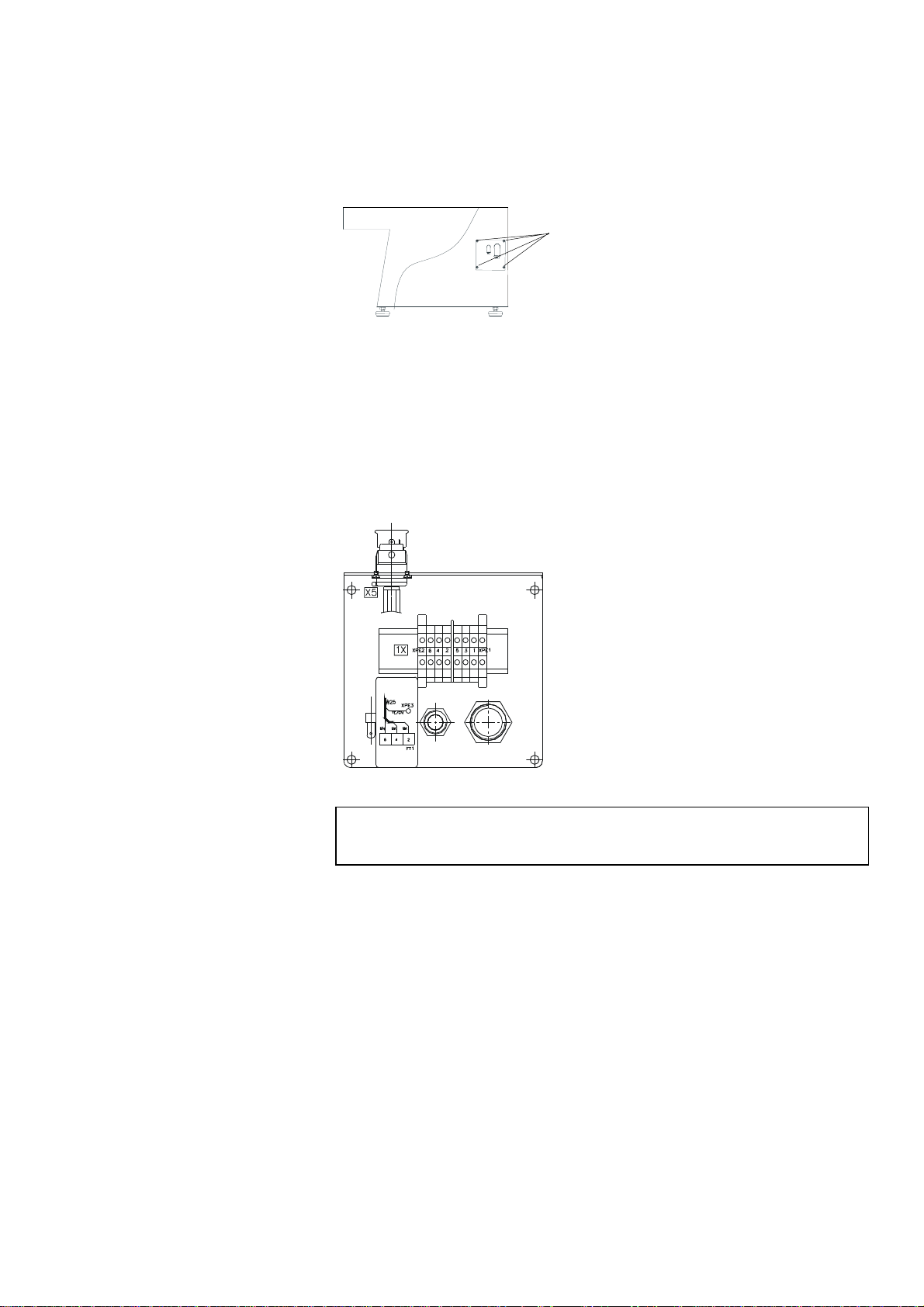
Remove the 4 Allen screws, on the right hand side of the
machine, securing the electrical panel, and let the electrical
panel rest on the two tabs.
Lead the cable through the relief angle and connect the 3
phases and earth according to local regulations.
In case of an external Recirculation Cooling Unit, connect the
electrical cable from the pump, according to the diagram
inside the panel.
The preparation disc should rotate counter-clockwise.
If the direction of rotation is clockwise, switch off AbraPol-10 and
unplug the machine.
Change two of the phases.
Repeat the rotation check.
Supplying Power
IMPORTANT
Check that the mains voltage corresponds to the voltage stated on the type
plate on the side of the machine.
Direction of Rotation
A
llen screws
AbraPol-10
Instruction Manual
6
Connect the compressed air supply with the inlet on the rear,
left side of the machine by means of the air hose and the hose
connection delivered with the machine.
Fasten the air hose with a hose clamp.
The pressure supply should be 6-10 bar and should be supplied
either from a central compressor, portable compressor with
compressed air reservoir or compressed-air bottle. A capacity of 20
l/min at atmospheric pressure is sufficient.
Please refer to the section on Technical Data for recommended air
quality.
An exhaust system can be connected when using alcohol based
suspensions or lubricants.
Slot the 50 mm pipe angle connection into the hole on the left
hand side of the splash guard and connect to the exhaust system.
Recommended capacity for exhaust system: 180m3/h at 0mm
water gauge.
Supplying Compressed Air
Connection to an External
Exhaust System

AbraPol-10
Instruction Manual
7
Place the unit where you find it convenient, either inside the
machine or outside, on the left.
Connect the inlet hose from the dosing arm to the pump of the
Recirculation Cooling Unit and tighten the clamp.
(If the cooling unit is placed outside the machine, pass the
hose under the cabinet).
Lead the electrical cable into the electrical panel and connect
to the terminal points.
(If the cooling unit is placed outside, lead through the angle
on the panel).
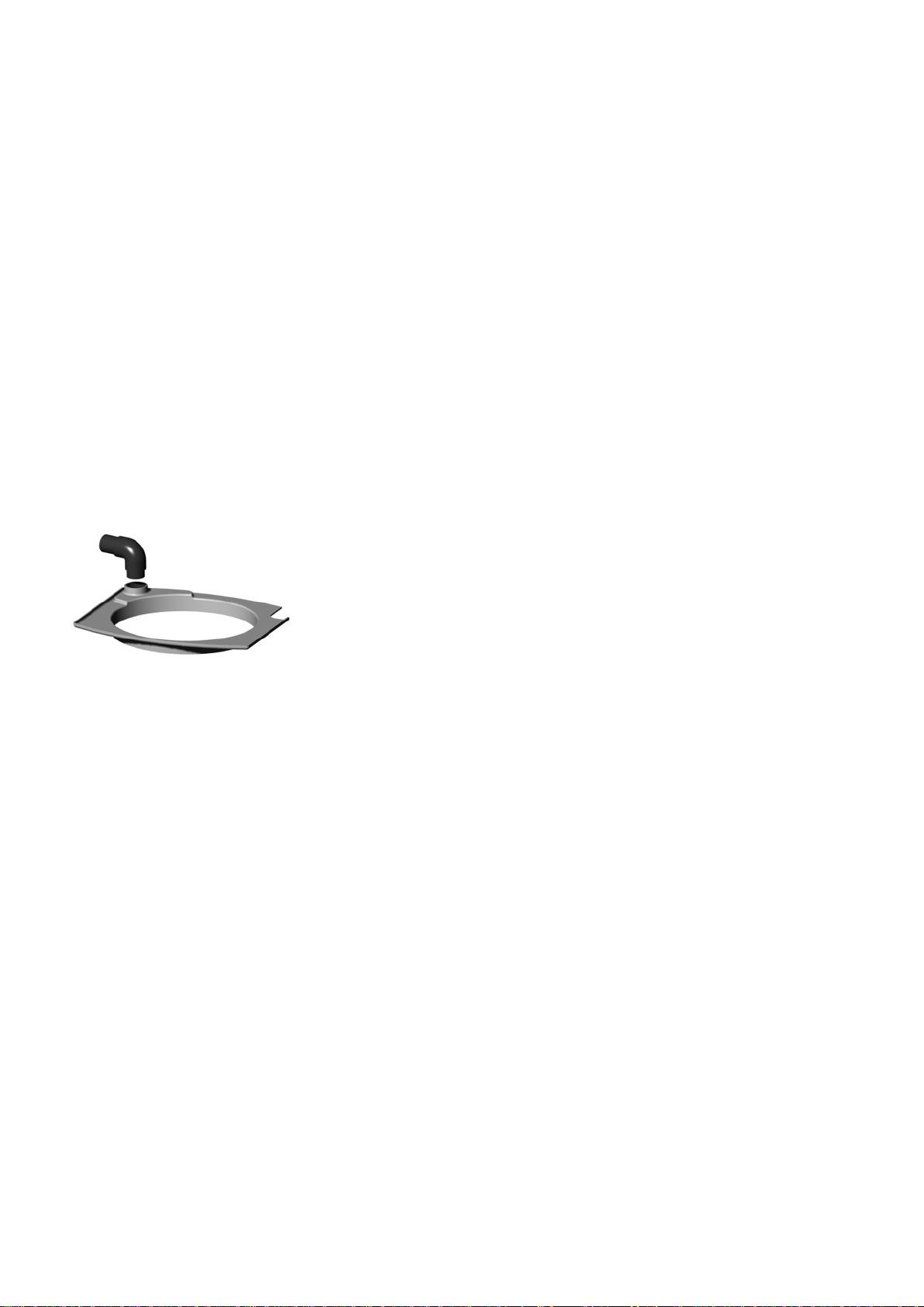
Slot the 900 drain angle into the pipe in the top of the
reservoir lid. (Note: The 450elbow pipe delivered with the
Recirculation Cooling Unit is not used with this machine).
Cut the drain hose to an appropriate length, and twist it into
the hole located on top of the unit.
(If the cooling unit is placed outside, lead the drain hose
through the hole on the rear left of the machine).
Check that there is a steady fall on the whole course of the
outlet hose.
Check that when the power is turned on, the pump rotates in
the direction indicated by an arrow on the top of the pump. If
not, change two of the phases on the pump motor cable.
Replace the panel/ back plate.
Place a disposable plastic insert in the tank and fold it over
the rim.
Fill the tank with 29.1 l water and 900 ml Struers Additive
for Cooling Fluid.
The water level should be 8-10 cm below the upper rim of the
tank.
Fit the tank lid and sieve.
Replace the front cover.
Mounting a Recirculation
Cooling Unit (accessory)
Warning
Disconnect the machine from the mains power supply before connecting or
disconnecting the recirculation pump.
Note!
The Recirculation Cooling Unit cannot be positioned outside the machine
when an outlet kit (ABTDR) is also used.
IMPORTANT
Too high a level of coolant in the tank might damage the pump. To avoid
this, place the disposable insert so that the pre-punched hole is in front of
the overflow aperture in the tank.
Always maintain the correct concentration of Struers Additive in the cooling
water (percentage stated on the Additive container).
Remember to top up with Struers Additive each time you refill with water.
Inlet hose 90
0
drain angle
AbraPol-10
Instruction Manual
8
Place the filled bottles in the dosing unit and connect the
tubing.
Enter the bottle details in the Bottle Configuration menu to
make them available for preparation methods. See “Setup
Bottle Configuration”.
The tubes can easily go through the bottle unit to reach larger
containers placed on the floor e.g. Lubricants.
Disconnect main power.
Open the doors to the bottle unit.
Remove the rectangular cover plate with the 4 mm Allen
key supplied.
Remove the cover plate located on the left side of the machine
with the supplied 4 mm Allen key supplied, and loosen the
plug.
Lead the reinforced water hose from the hole on the left,
through the hole in the reinforcement beam on the inside of
the bottle unit, and through the rectangular hole in the dosing
unit.
Connect the hose to the additional dosing unit, and tighten
the clamp.
Place the ½" - ¾" fitting in the hole ( ¾" on outside) and
tighten the ½" nut.
Connect the reinforced hose to the ½" thread.
Placing Bottles in the
Dosing Unit
Nb!
OP-X can not be placed on the floor.
Mounting an Additional Dosing
Unit (accessory)
ABTDO
plug
AbraPol-10
Instruction Manual
9
Connect the plug on the additional dosing unit to the plug
located in the bottom of the dosing unit.
Replace the two cover plates.
Connect the white water hose to the ¾" thread.
Mount the straight end of the pressure hose onto the water
inlet tube on the back of AbraPol-10:
− Insert the filter gasket in the coupling nut with the flat
side against the pressure hose.
− Tighten the coupling nut completely.
Mount the other end of the pressure hose on the water mains
tap for cold water:
− Mount the reduction ring with gasket on the water mains
tap, if necessary.
− Introduce the gasket and tighten the coupling nut
completely.
Connect the silicone tubes to the inlets/outlets of the dosing
pumps.
Check that the reinforced hose does not interfere with the
belts.
Reconnect main power and allocate the bottles.
NB
Remember the earth connections.
NB
OP-X suspension can only be used in bottle 4.
AbraPol-10
Instruction Manual
10
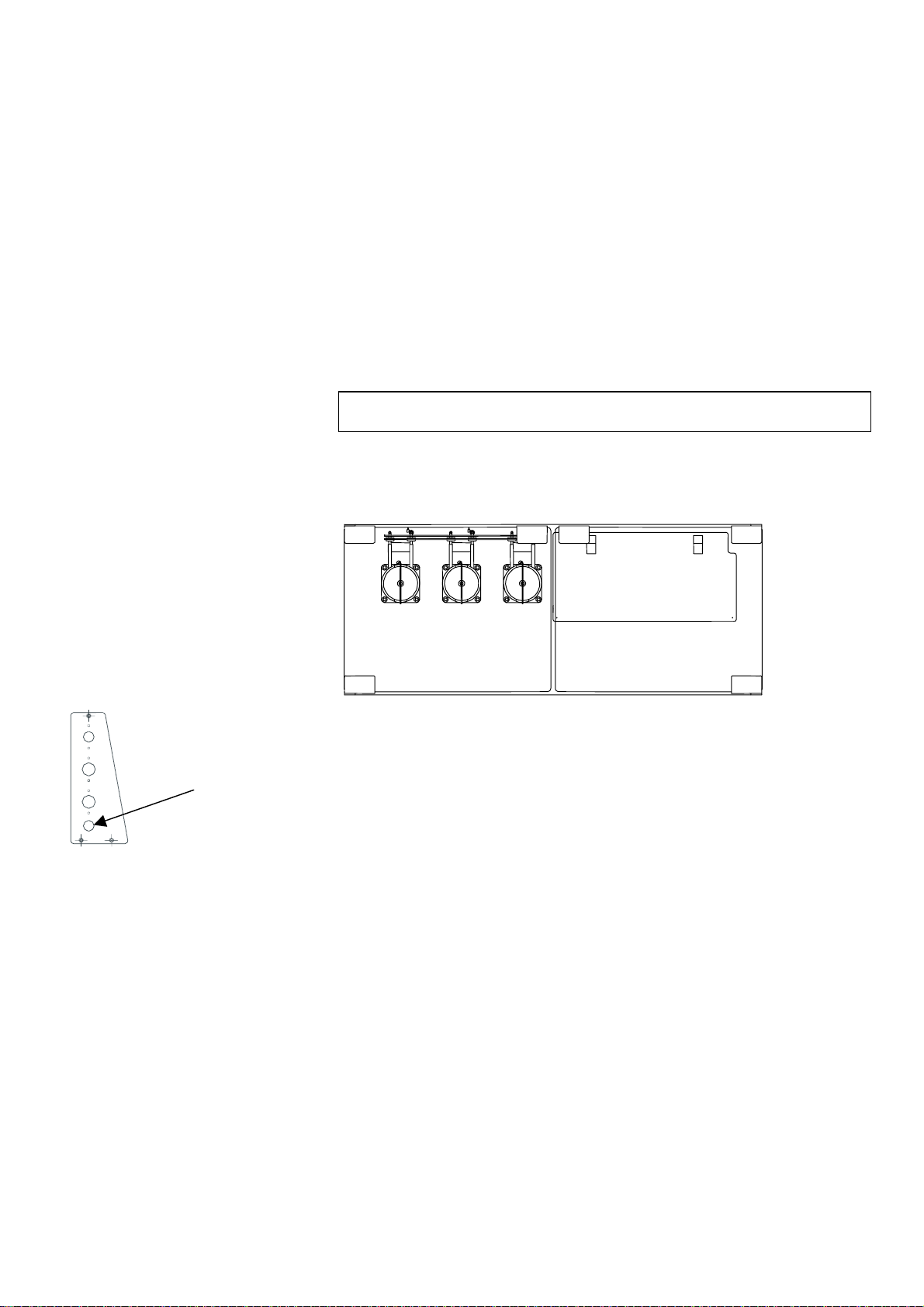
Disconnect main power.
Remove the lower front cover plate.
Remove the Recirculation Cooling Unit, if there is one.
Take the entire unit, and place it in position by letting the two
Allen bolts slide into the slots located in the left rear side.
Tighten the Allen bolts.
A
B
C
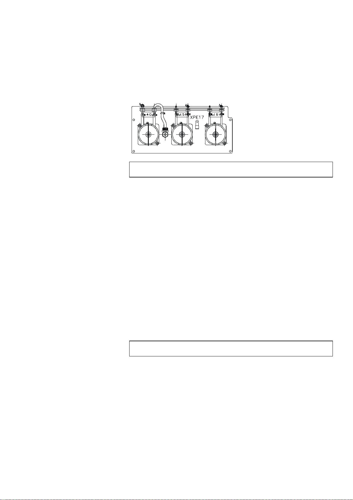
Strip the steel spring from approx. 3 cm of the drain hose and
cut. Bend the cut end of the steel spring inwards towards the
centre of the hose. Mount the drain hose onto pipe Aand
clamp the stripped section using a hose clamp.
Take another piece of drain hose and check that it is long
enough to reach the Recirculation Cooling Unit. Mount onto
pipe B. (Strip some steel spring from the hose and secure the
hose as described earlier).
Connect to the Recirculation Cooling Unit.
Connect a piece of drain hose from the outlet at the rear (C)
and lead to the drain.
Reposition the Recirculation Cooling Unit.
Make sure that the hoses do not interfere with the belts.
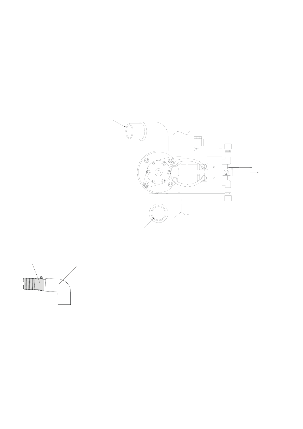
Mounting the Outlet Kit
(accessory)
ABTDR
Lead outlet hose
to the drain
Connect to
Recirculation Cooling Unit
Connect to
drain hose
Stripped
hose Pipe

AbraPol-10
Instruction Manual
11
Locate the electrical cable for the air solenoid valve (located
on the inner left side of the machine) and remove the cap
covering the stripped wires.
Open the cover of the DIN terminal by removing the screw
and connect the wires to the terminals.
Replace the cover for the DIN terminal.
Find the air supply hose and cut off the plug (stopper). Fix the
cut end into the air supply inlet.
Replace the front cover and reconnect main power.
Note:
It is not important to which terminal the wires are connected,
each wire can be connected to either terminal.
Air supply inlet
Air supply hose
DIN terminal
Screw

AbraPol-10
Instruction Manual
12
Disconnect main power.
Remove the lower front cover plate.
Remove the cover plate located on the left side of the machine
with the supplied Allen key, and break loose the plug.
Mount the water solenoid valve with the supplied Allen bolts
and key according to the type plate.
Connect the two blades (cable W23) to the solenoid.
Connect the reinforced hose from the doser arm to the hose
nipple, and tighten the clamp.
Be careful that the hose does not interfere with the belts.
Remount the cover plate.
Connect the white hose to the solenoid valve.
Mount the straight end of the pressure hose onto the water
inlet tube on the back of AbraPol-10:
− Insert the filter gasket in the coupling nut with the flat
side against the pressure hose.
− Tighten the coupling nut completely.
Mount the other end of the pressure hose on the water mains
tap for cold water:
− Mount the reduction ring with gasket on the water mains
tap, if necessary.
− Introduce the gasket and tighten the coupling nut
completely.
Replace the front cover and reconnect the main power.
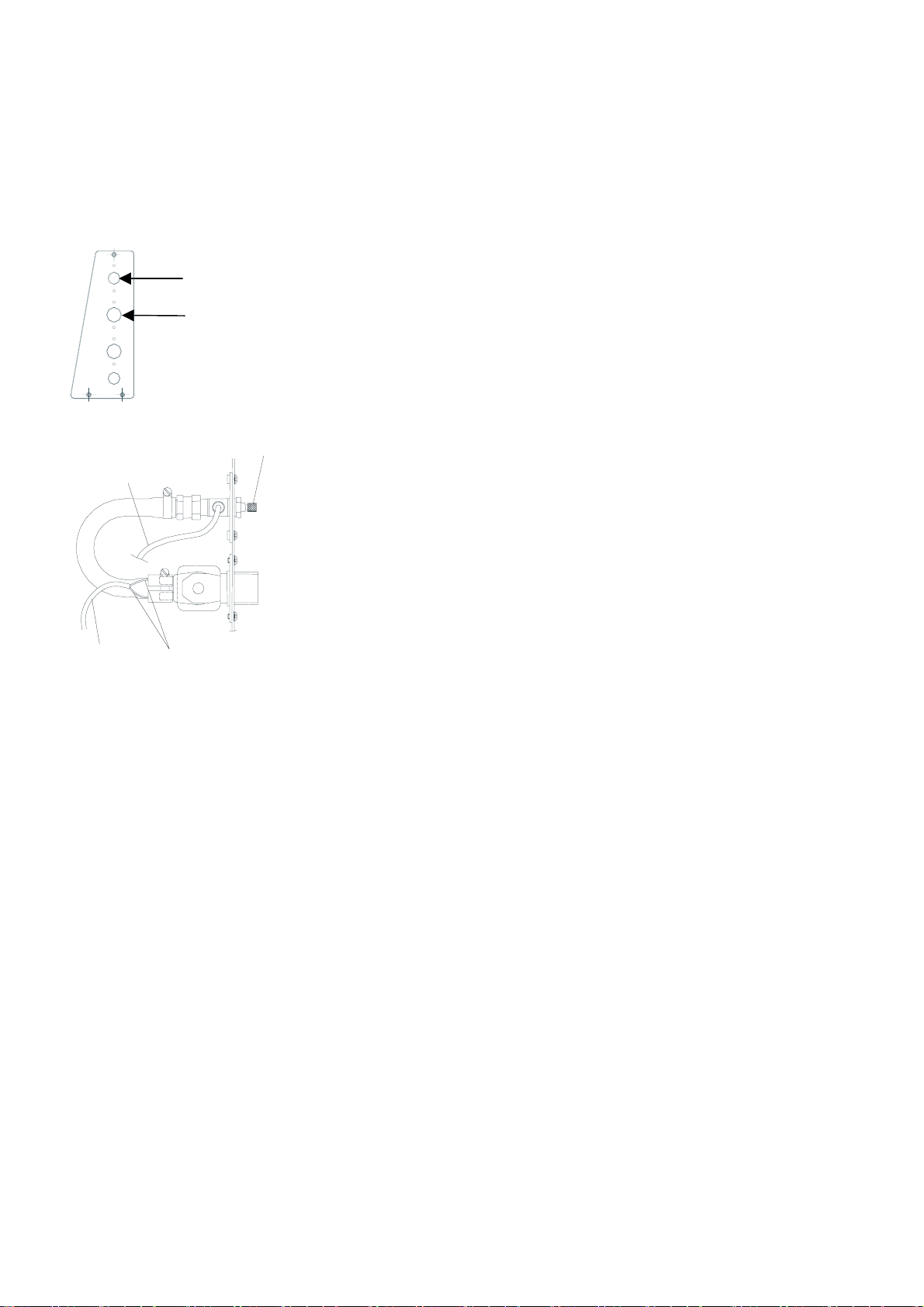
Mounting the Water Supply Kit
(accessory)
ABWAT
Blades
Hose nipple
Cable
W23
AbraPol-10
Instruction Manual
13
Disconnect main power.
Remove the lower front cover plate.
Remove the cover plate located on the left side of the machine
with the supplied Allen key, and break loose the plug.
Mount the water solenoid valve and the throttle valve with
the Allen bolts supplied.
Connect the two blades (cable W24) to the solenoid.
Cooling is factory installed; simply connect the grey hose (ø4)
from the nozzle to the single banjo located on the throttle
valve.
Remount the cover plate.
Connect the white hose to the solenoid valve.
Mount the straight end of the pressure hose onto the water
inlet tube on the back of AbraPol-10:
− Insert the filter gasket in the coupling nut with the flat
side against the pressure hose.
− Tighten the coupling nut completely.
Mount the other end of the pressure hose on the water mains
tap for cold water:
− Mount the reduction ring with gasket on the water mains
tap, if necessary.
− Introduce the gasket and tighten the coupling nut
completely.
Replace the front cover and reconnect main power
Should the rate of disc cooling require adjustment:
Loosen the contra nut and turn the regulator screw to the
required rate.
Re-tighten the contra nut.
Mounting the Disc Cooling Kit
(accessory)
Adjusting Disc Cooling
Water solenoid valve
Throttle valve
Blades
Grey hose
Cable
W24
Regulator
screw

AbraPol-10
Instruction Manual
14
Disconnect main power.
Remove the lower front cover.
Connect the plug on the removal sensor with the plug located
in the recess to the left of the control panel.
Take the removal sensor and gently slide it up in the hole
located in the bottom of the cast iron beam.
Let the bracket slide over the factory installed support
bracket.
From the left, slide the two screws through the brackets, and
tighten with a 10mm spanner.
Reconnect main power and follow the instructions on the
screen, using the tools supplied and the calibrating sticks.
Mounting the Stock Removal
Sensor (accessory)
ABMEU
Plug
Stock Removal Sensor
Slide up into
beam
Support bracket
Screws
Table of contents
Languages:
Other Struers Cutter manuals


