Struers Secotom-10 User manual

Manual No.: 15037001
Date of Release .0.2010
Secotom-10
Instruction Manual

Secotom-10
Instruction Manual
Table of Contents Page
User’s Guide....................................................................................1
Reference Guide..........................................................................31
Quick Reference..........................................................................43
Always state Serial No and Voltage/frequency if you have technical questions or when ordering spare parts.
You will find the Serial No. and Voltage on the type plate of the machine itself. We may also need the Date
and Article No of the manual. This information is found on the front cover.
The following restrictions should be observed, as violation of the restrictions may cause cancellation of
Struers legal obligations:
Instruction Manuals: Struers Instruction Manuals may only be used in connection with Struers equipment
covered by the Instruction Manual.
Service Manuals: Struers Service Manuals may only be used by a trained technician authorised by Struers.
The Service Manual may only be used in connection with Struers equipment covered by the Service Manual.
Struers assumes no responsibility for errors in the manual text/illustrations. The information in this manual is
subject to changes without notice. The manual may mention accessories or parts not included in the present
version of the equipment.
The contents of this manual is the property of Struers. Reproduction of any part of this manual without the
written permission of Struers is not allowed.
All rights reserved. © Struers 2010.
Struers A/S
Pederstrupvej 84
DK-2750 Ballerup
Denmark
Telephone +45 44 600 800
Fax +45 44 600 801
Secotom-10
Instruction Manual
Secotom-10
Safety Precaution Sheet
To be read carefully
before use
1. The operator should be fully aware of the use of the machine according
to the Instruction Manual and the instructions of the cut-off wheels.
2. The machine must be placed on a safe and stable support table. All
safety functions and guards of the machine must be in working order.
3. The unit must be installed in compliance with local safety regulations.
4. Use only intact cut-off wheels. The cut-off wheels must be approved for
min. 5,000 rpm.
5. When the manual cutting table is used, the machine is not to be used
with saw-blade type cut-off wheels.
6. Observe the current safety regulations for handling, mixing, filling,
emptying and disposal of the additive for cooling fluid.
7. To achieve maximum safety and lifetime of the machine, use only
original Struers consumables.
8. Struers recommends using cooling fluid when cutting as the materials
being cut may emit harmful dust. Additionally an adequate exhaust
system should be used.
9. The machine emits only moderate noise. However, the cutting process
itself may emit noise, depending on the nature of the workpiece. In
such cases, the use of hearing protection is recommended.
10. Always use Safety Goggles when using the manual cutting table on the
machine.
11. The machine must be disconnected from the mains prior to any service.
Wait until residual potential on the capacitors is discharged.
12. Do not cycle mains power more than once every three minutes.
Damage to the drive will result.
The equipment should only be used for its intended purpose and as detailed in the Instruction Manual.
The equipment is designed for use with consumables supplied by Struers. If subjected to misuse, improper
installation, alteration, neglect, accident or improper repair, Struers will accept no responsibility for
damage(s) to the user or the equipment.
Dismantling of any part of the equipment, during service or repair, should always be performed by a qualified
technician (electromechanical, electronic, mechanical, pneumatic, etc.).

Secotom-10
Instruction Manual
Disposal
Equipment marked with a WEEE symbol contain electrical and
electronic components and must not be disposed of as general
waste.
Please contact your local authorities for information on the correct
method of disposal in accordance with national legislation.

Secotom-10
Instruction Manual
1
User’s Guide
Table of Contents Page
1. Getting Started
Checking the Contents of the Packing Box........................................2
Removing Secotom-10 from the Pallet...............................................2
Placing Secotom-10...........................................................................2
Cover for Exhaust Hole......................................................................2
Getting Acquainted with Secotom-10.................................................3
Rear of Secotom-10...........................................................................4
Supplying Power ................................................................................5
Single-phase Supply.................................................................5
3-phase Supply.........................................................................5
Connection to the Machine.......................................................5
Mounting the Cut-off Wheel ...............................................................6
Adjusting the Height of the Cut-off Wheel..........................................7
Filling the Cut-off Machine with Cooling Fluid....................................8
Cutting Table......................................................................................9
Positioning the Cutting Table.............................................................9
Attaching Clamping Tools (accessories)..........................................10
Quick-clamping Device...........................................................10
Advanced Clamping Tools......................................................11
Electrical Connections in the Cutting Chamber................................12
Flushing Hose..................................................................................13
2. Basic Operation
Front Panel.......................................................................................14
Front Panel Controls ........................................................................15
Software Settings.............................................................................16
Setting the Language..............................................................17
Reading the Display.........................................................................18
Changing/Editing Values..................................................................19
Numeric Values.......................................................................19
Alphanumeric Values..............................................................20
Setting up the Software....................................................................21
Cutting Setup ...................................................................................22
Setting Wheel Speed..............................................................23
Setting Feed Speed................................................................24
Setting Cut Length..................................................................25
Setting X Position (accessory.................................................26
Chuck Mode (accessory)........................................................28
Starting the Cutting Process ............................................................29
During Cutting.........................................................................29
Stopping the Cutting Process...........................................................30

Secotom-10
Instruction Manual
2
1. Getting Started
In the packing box you should find the following parts:
1 Secotom-10
2 Mains cables
1 Stop pin
1 Socket spanner 17 mm
1 Socket spanner 13 mm
1 Hose for connection to exhaust, 1.5 m x 32 mm dia.
1 Hose clamp, 25-40 mm dia
1 Cover for exhaust hole
1 Instruction Manual Set
Secotom-10 is secured to the wooden pallet with 3 screws. Remove
these screws with a 13 mm socket spanner.
Secotom-10 should be placed on a safe and stable support table with
an adequate working height. The table must be able to carry at least
55 kg. The machine must be placed close to the power supply.
The exhaust pipe at the back of the cutting chamber can be replaced
with the cover for the exhaust hole if Secotom-10 is not to be
connected to an exhaust system.
Checking the Contents of the
Packing Box
Removing Secotom-10
from the Pallet
Placing Secotom-10
Cover for Exhaust Hole
Secotom-10
Instruction Manual
3
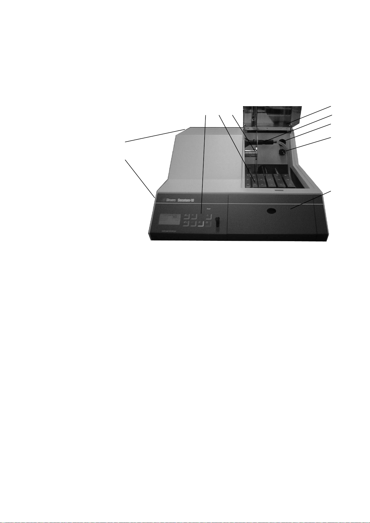
Take a moment to familiarise yourself with the location and names of
the Secotom-10 components.
Control panel (see 2. Basic Operation)
Movable cutting table
Cut-off wheel mounting
Transparent cover
Cooling fluid nozzles
Ventilation hole
Electrical connection socket
Cover (housing cooling fluid bath and cut-off wheel speed guide)
Cut-off wheel height adjustment control
Main switch (at the back of the machine)
Getting Acquainted with
Secotom-10
Secotom-10
Instruction Manual
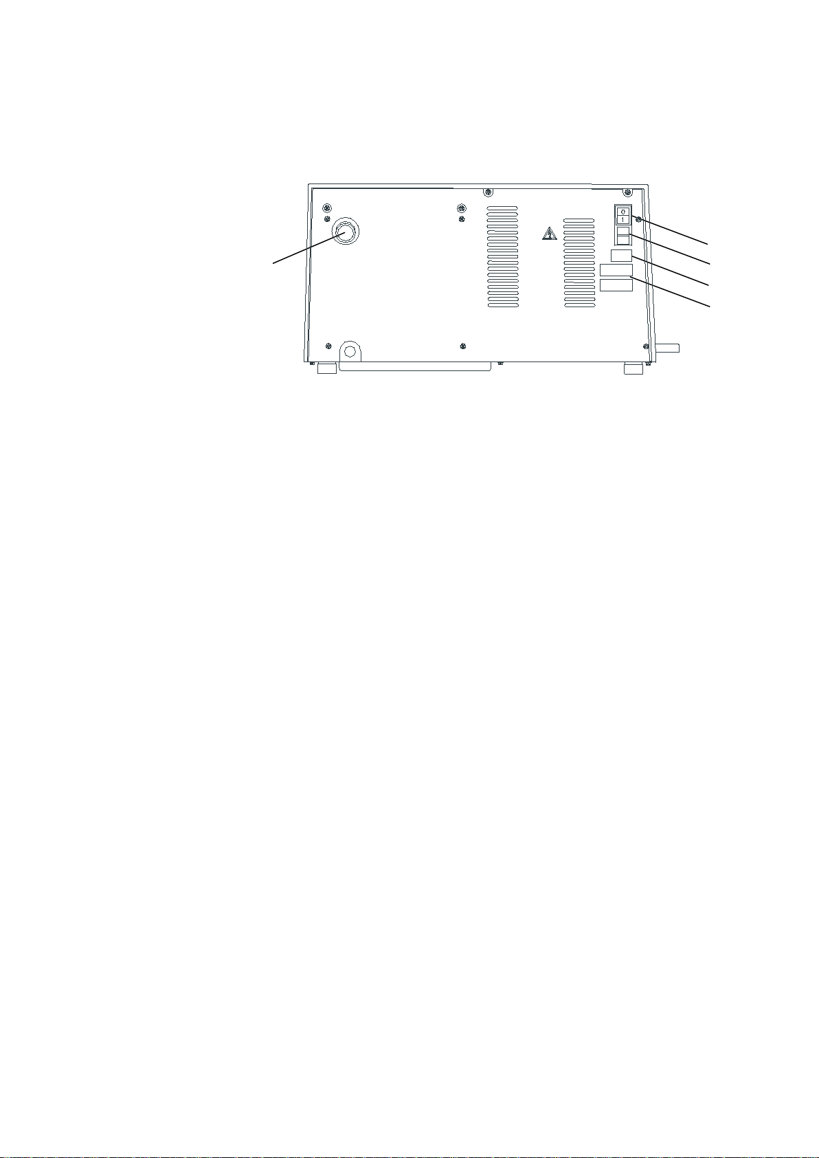
4
Ventilation Hole
Main switch
Fuses
Mains connection
Type Plate
Rear of Secotom-10

Secotom-10
Instruction Manual
5
Always remember to switch the power off when installing electrical
equipment!
The Secotom-10 is shipped with 2 types of Mains cables:
The 2-pin (European Schuko) plug is for use on single-phase,
200-240 V connections.
If the plug supplied on this cable is not approved in your country,
then the plug must be replaced with an approved plug. The leads
must be connected as follows:
Yellow/green: earth
Brown: line (live)
Blue: neutral
The 3-pin (North American NEMA) plug is for use on 3-phase,
200-240 V power connections.
If the plug supplied on this cable is not approved in your country,
then the plug must be replaced with an approved plug. The leads
must be connected as follows:
Green: earth
Black: line (live)
White: line (live)
Both cables are on the other end equipped with an IEC 320 cable
connector that has to be connected to the Secotom.
Supplying Power
DANGER!
The machine must be earthed
IMPORTANT
Check that the mains voltage corresponds to the voltage stated
on the type plate on the back of the machine.
Single-phase Supply
3-phase Supply
Connection to the Machine
WARNING!
The output voltage from this cable is 200 – 240V and not 110V.
DO NOT use this cable to connect equipment that use a 110V power
supply. Failure to adhere to this may result in material damage.
Secotom-10
Instruction Manual
6
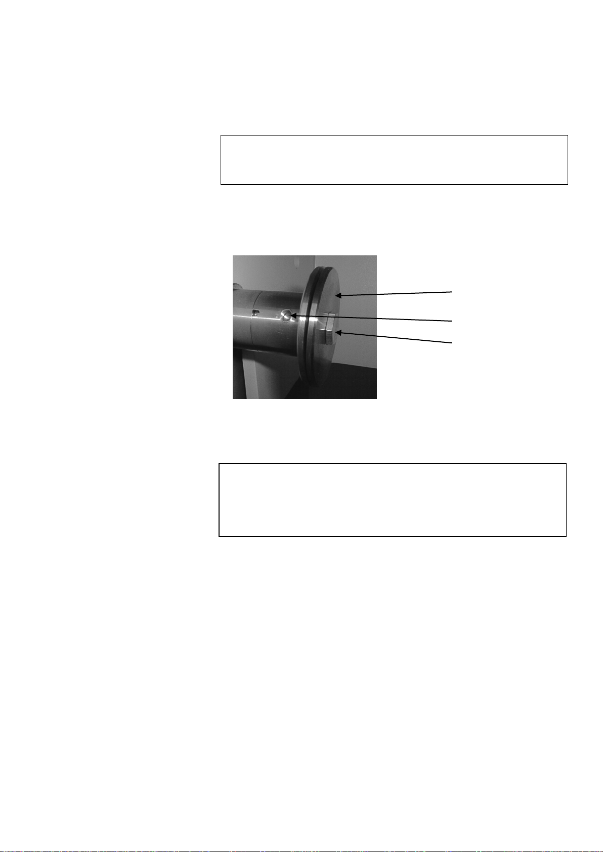
Lift the transparent cover to an angle of 450-600.
Lift the cooling fluid nozzles to gain access to the cut-off wheel
mounting.
Insert the stop pin into the hole of the inner flange.
Use the fork spanner (17 mm) to loosen the flange screw.
Remove the outer flange.
Mounting the Cut-off Wheel
IMPORTANT
For manual cutting: only diamond or CBN cut-off wheels with a metal body
are allowed. Abrasive SiC or Al2O3cut-off wheels or saw blades may not be
used when the manual cutting table accessory is fitted to the Secotom-10.
IMPORTANT
The tolerance between the spindle and inner flange is very small which
means that the two surfaces must be absolutely clean.
Never try to squeeze the cut-off wheel on as this may damage the spindle
or the cut-off wheel. If there are any small burrs, remove them with grinding
paper (grit size 1200).
Outer flange
Flange screw
Hole for stop pin

Secotom-10
Instruction Manual
7
Mount the cut-off wheel (using the 22mm insert if necessary) and
remount the outer flange, with the machined face towards the
inner flange.
Insert the locking pin in the hole in the inner flange.
Gently fasten the flange screw using the fork spanner 17 mm.
Lower the cooling fluid nozzles to their operating positions.
The distance between the cut-off wheel spindle and the cutting table
can be adjusted to suit the individual cut-off wheels or wear caused
during the cutting process.
Use the control on the side of the Secotom-10 (illustrated in
“Getting Acquainted with the Secotom-10”) to raise and lower
cut-off wheel mounting.
IMPORTANT
When mounting cut-off wheels with a 12.7 mm centre hole, make sure that
the 22 mm arbour insert has been removed. Failure to do this will result in
the cut-off wheel being pressed out of shape.
Adjusting the Height of the
Cut-off Wheel
Inner flange
Hole for stop pin
12.7 mm axle
Insert for wheels with
22 mm arbour hole

Secotom-10
Instruction Manual
8
The Secotom-10 has a built-in cooling fluid system. The fluid coming
from the nozzles passes over the cut-off wheel and collects in the
bottom of the cutting chamber; where it then returns to the bath,
which is located under the cutting chamber. Access to this bath, for
cleaning and maintenance purposes, is possible by opening the front
cover of the Secotom-10.
Open and remove the front cover from the Secotom-10.
Lift the inlet tube (as illustrated).
Slide the fluid bath out gently.
Empty any old/used fluid from the bath and ensure that the bath
is clean (free from cutting debris).
Fill the bath with 3.69 litres of water and 110 ml Struers additive
for cooling fluid (Corrozip).
Slide the fluid bath back into position.
Check that the inlet tube is placed correctly so that the pump is
supplied with water.
Filling the Cut-off Machine
with Cooling Fluid
IMPORTANT
Always ensure that there is sufficient water in the tank as the recirculation
pump will be damaged if it is run dry.
Secotom-10
Instruction Manual
9
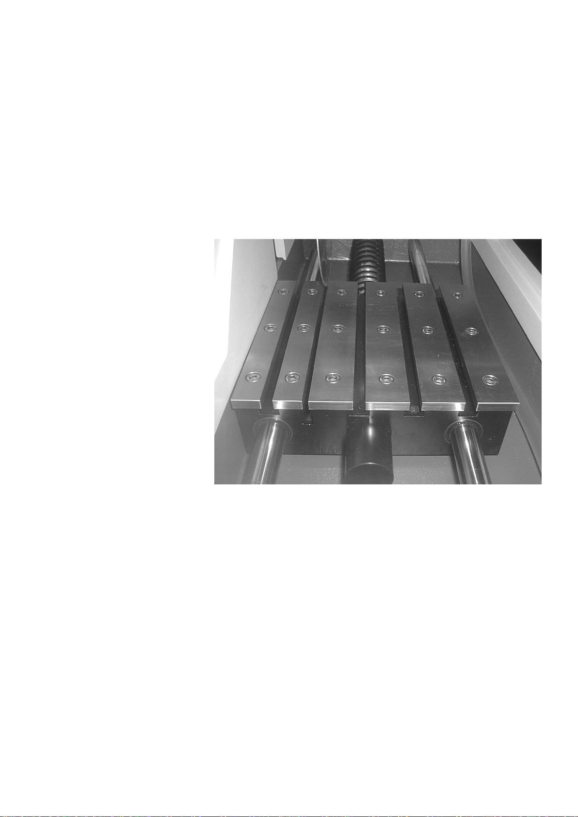
The Secotom-10 is fitted with a moving cutting table. Movement of
the table is controlled using the joystick on the Control Panel and
through the software, which is described in section 2. Basic
Operation. The table has several 8 mm T-slots, which are used to
secure clamping tools. This ensures that workpieces are held
securely during the cutting process. Although these clamping tools
are available as accessories, details about the table and the
clamping tools are described in this and the following sections.
Although during the cutting process the table movement is controlled
through Secotom-10’s software, prior to starting the cutting process,
it is necessary to position the cutting table manually.
Use the joystick on the Control Panel to move the cutting table.
Pull the joystick towards you to move the cutting table away from
the cut-off wheel, or push the joystick away from you to move the
cutting table towards the cut-off wheel.
Cutting Table
Positioning the Cutting Table

Secotom-10
Instruction Manual
10
There are several types of clamping tools available as accessories (a
complete list is provided in the Accessories section). Some of these
are plain, manual quick-clamping tools while others provide more
sophisticated features, and need to be positioned accurately on the
cutting table and require an electrical supply.
Position the back stop and the Quick-clamping device as shown
in the illustration.
Tighten the nuts to secure the Quick-clamping device.
Attaching Clamping Tools
(accessories)
Important!
When fitting clamping tools, always ensure that they cannot come in contact
with the cut-off wheel. Failure to do this may result in the clamping tools
being damaged.
Quick-clamping Device

Secotom-10
Instruction Manual
11
Place the clamping tool on the cutting table so that the securing
bolts align with the T-slot on the right hand side of the cutting
table.
Slide the clamping tool backwards and forwards to insert the
securing bolts in the T-slot.
Press the clamping tool sideways so that the positioning studs
are pressed tight against the table.
Hold the clamping tool in position and tighten the nuts to secure
the clamping tool.
Connect the clamping tool cable as described in Electrical
Connections in the Cutting Chamber on the next page.
A pop-up on the display panel confirms that the unit is now
connected.
The advanced clamping tools are fitted with a dovetail that
accommodates all our standard specimen holders for precision
cutting (a complete list is provided in the Accessories section).
Advanced Clamping Tools

Secotom-10
Instruction Manual
12
Some of the accessories for the Secotom-10, for example the
Manual Cutting Table and the advanced clamping tools require
electrical connections. These are supplied through the electrical
connection socket in the cutting chamber.
Remove the cover on the electrical connection socket in the
cutting chamber.
Using the cable fitted to the clamping tool, connect it to the
electrical connection socket.
Gently tighten the securing ring.
Electrical Connections in the
Cutting Chamber
Important
Always replace the socket’s protective cover when not in use.
Note
The different advanced clamping tools can be exchanged while Secotom-10
is switched on.
Note
The plugs on these clamping tools provide specific pin connections. If for
some reason you have a problem with a connection,
do not attempt to change the connections in the clamping tool plugs or
connection socket.
Securing ring
Plug

Secotom-10
Instruction Manual
13
The Secotom-10 comes complete with a flushing system. This
enables the cutting chamber to be rinsed clean of any debris
discarded during the cutting process. Flushing is operated through
the Control Panel buttons.
Remove the hose from the cooling fluid nozzles.
Holding the hose in the cutting chamber, press FLUSH .
To stop flushing, press FLUSH again or STOP .
Flushing Hose
Warning!
Do not start the flush function until you have removed
the hose from the fluid nozzles and are pointing it
into the cutting chamber.
Important!
Remember to replace the hose when you have finished flushing the cutting
chamber.
Secotom-10
Instruction Manual
14
2. Basic Operation
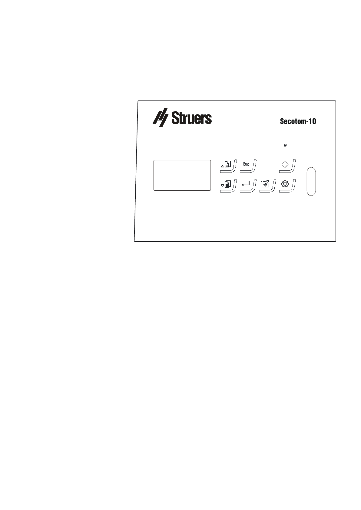
Power
Spindle speed 300 500 rpm:-
Front Panel

Secotom-10
Instruction Manual
15
This provides information about the individual buttons on the front
panel of the Secotom-10.
Pos. No. Key Function
Pos. No. Key Function
Moves cursor in display upwards
or increases the value when
editing parameter values.
Push button for starting and
stopping the FLUSH operation.
Moves cursor in display
downwards or decreases the
value when editing parameter
values.
Push button for starting the
cutting process.
Esc Leaves the present menu or
aborts functions/changes.
Push button for stopping the
process currently active.
Enables selected parameter
values to be activated for editing.
Saves the edited parameter
values.
Front Panel Controls
Secotom-10
Instruction Manual
16
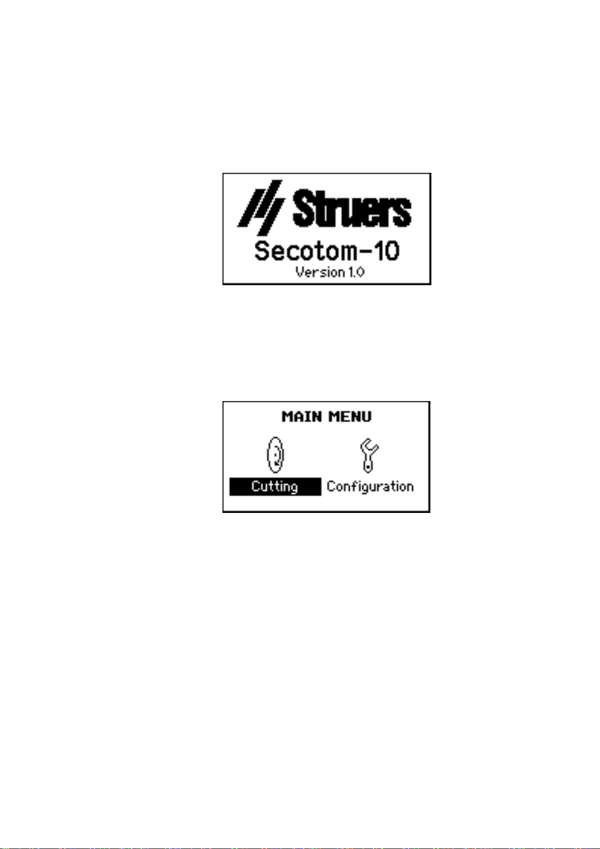
Switch on the power at the main switch located at the rear of the
machine. The following display will appear briefly:
The display will then change to the last screen shown before the
Secotom-10 was switched off. When switching on Secotom-10 for
the first time, the MAIN MENU will appear. If the heading in the
display is different, press Esc, until the MAIN MENU appears.
The MAIN MENU is the highest level in the menu structure. From this
menu, you can enter the configuration menu and cutting menu.
Software Settings
Table of contents
Languages:
Other Struers Cutter manuals


