EN-6
Product Description and Intended
Use
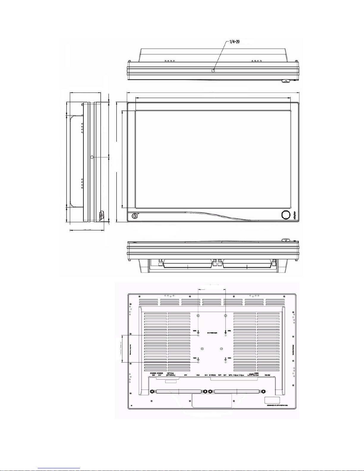
The VISION ELECT HDTV (model 240-030-960) High Definition LCD
Monitor is an intelligent, microprocessor-based TFT-LCD monitor
intended for use in endoscopic surgical applications. It has an
ergonomically designed display and is compatible with most analog
RGB (Red, Green, Blue) display standards.
The VISION ELECT HDTV (model 240-030-960) monitor has the
following features:
• Advanced Viewing Solution (AVS): A sophisticated filter
extends the viewing angle of the screen image, without
sacrificing contrast ratio and brightness.
• Upgraded video cards or software will not require buying a new
monitor because of the wide auto-scanning compatibility range.
• The internal microprocessor digitally controls auto-scanning, for
horizontal scan frequencies between 31.47 KHz and 78.88 KHz,
and vertical scan frequencies between 50.0 Hz and 85.1 Hz. In
each frequency mode, the microprocessor-based circuitry allows
the monitor to function at the precision of a fixed frequency.
• The resident memory allows for storing factory default settings
and also additional user adjustment parameters.
• The maximum resolution achievable is WUXGA (1920 × 1200,
60Hz).
• The monitor is compliant with the VESA-DPMS power-
management standard. In order to save energy, the monitor
must be connected to a system compliant with the standard.
• The monitor is designed to mount an accessory (such as a
camera or speaker) with a 2 lbs (max) load per hole.
• The monitor is certified by UL International in accordance with
medical standard UL 60601-1. It is also CE marked for sale in
the European Community for integration or use with medical
products.
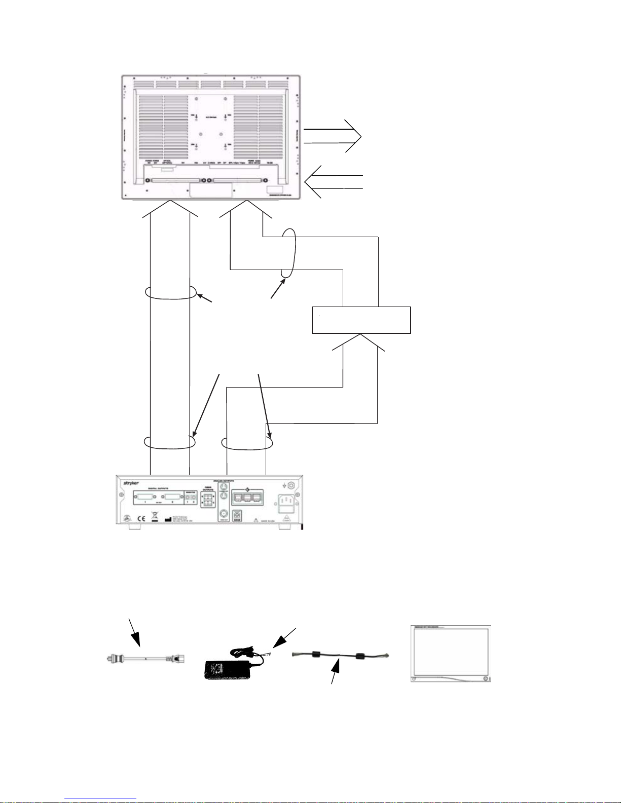
Product Contents
1. Carefully unpack the VISION ELECT HDTV (model 240-030-960)
monitor. Save the original carton and associated packing
material. They will be useful should you have to transport or ship
the unit.
2. Check the monitor and its accessories for any damage that may
have occurred during shipping. Immediately report any damage
to the shipping company.