Hirose GT43 User manual

ETAD-P0398 First edition
GT43 Harness
Shielding Plate Assembly
Process
Instruction Manual
Dec.1.2023Copyright2023HIROSEELECTRICCO.,LTD.AllRightsReserved.

CAUTION
In order to use the product safely, be sure to read this instruction manual before using
the product. Furthermore, keep this instruction manual in a place where it can be
accessed quickly when needed.
Dec.1.2023Copyright2023HIROSEELECTRICCO.,LTD.AllRightsReserved.

FORWARD
Thank you very much for purchasing our GT43 harness equipment.
This tool is a jig to assemble shielding plate to the external cylinder terminal of the harness product.
Be sure to read this instruction manual carefully and fully understand itscontents before using the product.
Dec.1.2023Copyright2023HIROSEELECTRICCO.,LTD.AllRightsReserved.

i
FOR SAFE OPERATION
Because of the machine's design, there is always a possibility of contact with moving parts.The operators
of the machine and the maintenance personnel who are in charge of maintenance and repair work are
required to read the following SAFETY INSTRUCTIONS so as to avoid injury.
To fully understand the descriptions given in this Instruction Manual and the warning labels attached on
the machine, the warning messages are used in accordance with the below-stated classification. Please
be sure to thoroughly understand the messages and follow the instructions.
( I ) Description of warning messages
DANGER :
Used in the case where it is assumed that misuse of the machine will expose the operator
to immediate danger of major injury or death.
WARNING :
Used in the case where it is assumed that misuse of the machine can expose the operator
to danger of major injury or death.
CAUTION :
Used in the case where it is assumed that misuse of the machine can expose the operator
to danger of injury and can cause damage to property.
* Determine the degree of impairment referring to the below-stated classification.
Major injury
:
Indicates the loss of eyesight, wounds, burns (hyperthermal and hypothermal
burns), electric shocks, fracture of a bone, poisoning, etc. requiring emergency
of extended medical care.
Minor injury
:
Indicates wounds, burns, electric shocks, etc. requiring medical treatment.
Property damage
:
Indicates damage to the machinery and or the surrounding area.
Dec.1.2023Copyright2023HIROSEELECTRICCO.,LTD.AllRightsReserved.

ii
PRECAUTIONS FOR SAFETY
CAUTION
Basic safety instructions
1. Be sure to read this Instruction Manual and any other instructions or materials supplied with
the unit as accessories. Keep this Instruction Manual and make it available for reference.
Safety device and warning labels
1. To avoid possible accidents due to lack of the safety device, be sure to operate the machine
after ascertaining that the safety device is properly installed at the predetermined position.
Refer to page viii for detailed description of the safety device.
2. If the safety device is detached from the machine for any reason, replace it to its original
position and check to be sure that it normally functions.
Application
1. This machine shall only be used as specified in this Instruction Manual.
2. Modifications to this machine is prohibited. We assume no responsibility for accidents
resulting from modifications.
Operating environment
1. To avoid accidents caused by malfunction, the machine shall be operated under an
environment that is not affected by high noise sources (electromagnetic waves) such as high-
frequency welders.
2. To avoid accidents caused by malfunction, the machine shall not be used in such an
environment that would subject it to any voltage rating outside of "rated voltage ±10%".
3. The machine shall be used under the following environment for safety.
Atmospheric temperature under operating conditions : 5°C to 35°C
Relative humidity under operating conditions : 35% to 85 %
4. Condensation can be observed when the environment of the machine is changed abruptly
from cold to warm. To avoid accidents or damage, do not operate this machine in condition
where the humidity is greater than the upper limit of the relative humidity specified above.
5. To avoid accidents caused by a damaged electrical part function, in the event of thunder and
lightning, stop your work and pull out the power plug.
Training
1. To prevent possible accidents caused by unfamiliarity with the operation of the machine, the
machine should only be operated by fully trained personnel. Itis recommended that a training
procedure be established by the employer and that the operator be provided with this
Instruction Manual for reference.
Working wear
1. To protect against possible accidents resulting in personal injury or damage to personal
property (i.e., clothing), be sure wear a work uniform or fit clothing with sleeve cuffs fastened.
2. The operator should secure their hair with a hat or ponytail to protect his/her hair from being
caught in the machine.
3. The operator should wear safe, rubber bottom, close toe shoes or work boots.
Event that requires turn-off of the power.
1. In the eventof abnormalconditions, machine failure or power failure, the powershould be turned
off immediately.
2. To protect against possible accidents caused by abrupt start of the machine, the power must be
turned off before conducting inspection, repair, or cleaning. Be sure to turn the power off when
the operator leaves the machine.
3. To pull out the power plug, hold the plug rather than the cord..
Dec.1.2023Copyright2023HIROSEELECTRICCO.,LTD.AllRightsReserved.

iii
Safety instructions in each category of work following
the delivery of the machine
Transportation
1. In order to avoid damage accident, this machine must be held by two or more people. Use a
wheeled platform when moving the machine.
2. The machine shall be lifted or moved in such a way that secures safety to avoid falling and
dropping.
3. To protect against accidents or damage to the machine re-package, if necessary, to achieve
the originally-delivered state. Prior to re-packaging, wipe off an oil gathered on the machine.
Unpacking
1. The product is packaged in a cardboard box. When unpacking, be careful not to drop the
machine, and take the machine out of the box carefully.
Installation
(1)Workbench
1. Use a table or a work bench that will sufficiently withstand the machine weight and the
reaction force developed while the machine is in operation.
2. If casters are to be mounted on the main unit of the work bench, use durable casters
provided with a locking mechanism.
(2)Cable and wiring
1. To prevent electric shocks, electrical leak or fire, be careful not to strain the cables at any
time.
2. To protect against hazards from electric shocks, electrical leak and fire, multiple
connection must be avoided. Plug the machine direct into a socket.
3. In order to avoid electric shock, electric leakage or fire, make sure that connectors are
firmly connected. Furthermore, when unplugging the connector, be sure to hold and pull
the connector.
(3)Grounding
1. In order to avoid electric leakage and accident due to dielectric strength voltage, have a
person with professional knowledge in electric install an appropriate power plug.
Before operation
1. To protect against possible accidents resulting in injury or death, check to be sure that
connectors and cables are in good condition and fastened securely.
2. To protect against possible accidents resulting in injury or death, never place hands in or
near moving parts of the machine.
Maintenance
1. To prevent possible accidents, repair and adjustment of the machine shall be conducted only
by maintenance personnel who have been trained on the machine. Any repair and
adjustment not specified in this Instruction Manual are prohibited. We assume no
responsibilityfor accidents caused by improper repair or adjustment including the use of non-
genuine part(s).
2. In order to avoid accidents due to unfamiliarity with the machine or accident due to electric
shock, repair or maintenance (including wiring) related to electric parts shall be undertaken
by a person who has professional knowledge in electric. Or, send a request for
repair/maintenance to us or to the dealer near you.
3. To protect against personal injury, check to be sure that screws and nuts are tightened after
the completion of repair/adjusting and/or replacement of parts.
4. Periodically clean the machine as long as it is commissioned. To prevent possible accidents
caused by an abrupt start of the machine during cleaning, be sure to turn the power off
including unplugging it, before beginning cleaning.
5. In the event that your machine fails to perform normally after repair/adjusting works,
immediately stop operation. Contact Hirose for service to protect against personal injury.
Dec.1.2023Copyright2023HIROSEELECTRICCO.,LTD.AllRightsReserved.

iv
SAFETY INSTRUCTIONS TO BE FOLLOWED WHEN USING THE
TOOLS FOR GT43 SHIELDING PLATE ASSEMBLY
DANGER
1. To protect against shock hazards, open the cover, if necessary, after turning
the power off and waiting for a minimum of five minutes.
CAUTION
1. To avoid possible accidents resulting in personal injury caused by being
caught in the moving parts of the machine, extreme caution has to be taken to
keep your hands, fingers, clothing, head or hair away from the moving parts
and surrounding area. Also, do not place any matter that is not necessary in
the use of the machine near any of the moving parts.
2. To protect against possible personal injury, when turning the power on, take
care to keep your hands, fingers, clothing, head or hair away from the moving
parts and the surrounding area. Also, do not place any matter that is not
necessary in the use of the machine near any of the moving parts.
3. To protect against electric shock and accidents caused by any damaged
electrical component, be sure to turn off the power switch before connecting
or detaching the power plug.
4. To protect against possible accidents caused by any damaged electrical
component,be sureto stop yourwork and disconnectthe powerplug for safety
purposes in the case of thunder and lightning.
5. In the case where the machine is suddenly moved from a cold to warm
weather conditions condensation can result. To protect against possible
accidents due to any damaged electrical component, turn the power on only
after making sure that no condensation is present.
Dec.1.2023Copyright2023HIROSEELECTRICCO.,LTD.AllRightsReserved.

v
CONTENTS
1. MODELAND SPECIFICATIONS ........................................................................................................... 1
1-1. Model........................................................................................................................................... 1
1-2. Specifications............................................................................................................................... 1
2. NAME OF EACH PART.......................................................................................................................... 2
3. INSTALLATION ...................................................................................................................................... 3
3-1. Cable connection, air tube connection, power connection.......................................................... 3
4. OPERATING PROCEDURE.................................................................................................................. 5
4-1. Pre-working preparation.............................................................................................................. 5
4-2. Working method........................................................................................................................... 6
4-3. Ending work................................................................................................................................. 7
5. CONFIRMATION OF THE QUALITY..................................................................................................... 7
5-1 Checking the shielding plate assembly dimensions..................................................................... 7
5-2. Checking the dimension of the shielding plate assembly position.............................................. 7
5-3. Checking the shielding plate cut off tab dimension..................................................................... 8
5-4. Appearance Inspection................................................................................................................ 8
6. SETTING METHOD AND OPERATIONAL FLOW................................................................................. 8
7. ADJUSTMENT AND SUPPLEMENTAL SPECIFICATIONS................................................................ 10
7-1. Adjustment of various speed controllers.................................................................................... 10
7-2.Adjustment of cable clamp transfer amount...............................................................................11
7-3. Control box default state............................................................................................................ 12
7-4. Control box IN-OUT table.......................................................................................................... 14
7-5. How to adjust air pressure sensor............................................................................................. 16
7-6.Adjusting the shielding plate assembly height........................................................................... 17
8. MAINTENANCE................................................................................................................................... 18
8-1. Daily maintenance..................................................................................................................... 18
8-2. Replacement of expendable parts............................................................................................. 18
8-3. List of expendable parts ............................................................................................................ 22
8-4. List of maintenance parts .......................................................................................................... 22
9. TROUBLESHOOTING......................................................................................................................... 23
Dec.1.2023Copyright2023HIROSEELECTRICCO.,LTD.AllRightsReserved.

1
1. MODEL AND SPECIFICATIONS
1-1. Model
Product serial number
HRS No.
1
GT43-1PS-CSB/CRAD (shielding plate assembly jig)
CL 902-5156-0
2
WGT43-SHIELD/CRAD (shielding plate cable transfer 1
set)
CL 902-5157-0
* Dedicated reel stand is not provided with this equipment.
In case a reel stand is required, the user is expected to provide one.
1-2. Specifications
Item
Specifications
Compatible connector
GT43-1P/S-CSB/753-1005-0-00
Compatible cable
Cable external diameter: φ3.0
Fabricated minimum cable length
MIN 400 mm
①GT43-1PS-CSB/CRAD
(Shielding plate assembly jig)
It is an air driven assembly jig. When the start SW is turned ON,
1 cycle operation is performed.
Equipment capacity
Assemble shielding plate to the external cylinder terminal.
Production capacity: 12 sec/piece (including assembly
fabrication time)
* It may vary depending on the skill level.
External dimension/weight (main body)
350 (W) x 300 (D) x 350 (H) mm/approximately 25 kg
External dimensions/weight
(control box)
160 (W) x 250 (D) x 70 (H) mm/approximately 1.5 kg
Power supply
AC100V (50/60 Hz)
Consumed power
Approximately 30 W
Air pressure setting range
0.5 - 0.6 MPa
②WGT43-SHIELD/CRAD
(Shielding plate cable transfer 1 set)
Transfer cable to shielding plate assembly position.
Equipment capacity
Move the cable clamp to its home position.
Production capacity: 12 sec/piece (including assembly
fabrication time)
* It may vary depending on the skill level.
External dimension/weight (main body)
300 (W) x 300 (D) x 300 (H) mm/approximately 23 kg
External dimensions/weight
(control box)
160 (W) x 250 (D) x 70 (H) mm/approximately 1.5 kg
External dimensions/weight (electric
wiring section)
100 (W) x 1150 (D) x 300 (H) mm/approximately 1.5 kg
Power supply
AC 100 V (50/60 Hz)
Consumed power
Approximately 30 W
Air pressure setting range
0.5 - 0.6 MPa
Presence/absence of environmental
load substance
Absence
Dec.1.2023Copyright2023HIROSEELECTRICCO.,LTD.AllRightsReserved.
2
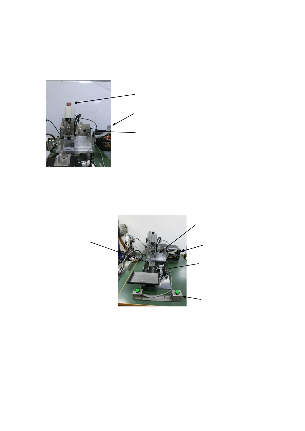
2. NAME OF EACH PART
①GT43-1PS-CSB/CRAD (shielding plate assembly jig)
This jig consists of the jig main body and the control box.
②WGT43-SHIELD/CRAD (shielding plate cable transfer 1 set)
This jig consists of the jig main body, the control box and the start switch.
Terminal guide
Air pressure sensor
Control box
Hirose genuine: shielding
plate assembly jig
Start SW
Cable clamp transfer section
Cable clamp set section
Terminal feeder
Dec.1.2023Copyright2023HIROSEELECTRICCO.,LTD.AllRightsReserved.

3
3. INSTALLATION
CAUTION
As this product is heavy, handle bytwo people and take sufficient safetymeasures
so that falling or dropping of the machine can be avoided during installation.
■Precaution for installation
Place the cable strip process equipment and the control box on a flat surfaced workbench which can
withstand heavy weight.
CAUTION: Do not install the machine in a place as described below.
(1) A place under direct sunlight.
(2) A dusty place.
(3) A place where temperature or humidity changes drastically.
(4) A place near a fire.
(5) A place near a volatile substance.
(6) A vibrating place.
(7) A place where the machine may get wet.
■Installation area (including working/maintenance area): 2 m x 2 m
CAUTION
In order to avoid accidents due to sudden unexpected start of the machine, start
working after turning the power OFF.
3-1. Cable connection, air tube connection, power connection
①Connect 2 rectangular connectors
of the control box for the shielding
plate assembly jig to the shielding
plate assembly jig.
②Connect the metal connector
connected to the electrical
component plate to the shielding
plate assembly jig and the control
box for the shielding plate
assembly jig.
③Connect the receptacle of the
control box for the shielding plate
assembly jig to 100 V power
supply.
Control box
(With a label for
conforming equipment)
Connection of rectangular
connector (small)
Connection of rectangular
connector (large)
Connection of metal
connector
(Connect with the electrical
component plate.)
Not used
Electrical
component plate
Control box
rear face
Shielding plate assembly
jig main body
rear face
Dec.1.2023Copyright2023HIROSEELECTRICCO.,LTD.AllRightsReserved.

4
④Connect 2 rectangular connectors
of the control box for shielding plate
cable transfer 1 set and round
shaped connector of the red box to
the electrical component plate.
⑤Connect the receptacle of the
control box for the shielding plate
cable transfer 1 set to 100 V power
supply.
* 100 V service power supply is
provided on the rear face of the
control box.
⑥Connect the start SW to the rear
face of the control box for shielding
plate cable transfer 1 set.
⑦Supply air to the regulator of the
electrical component plate and the
shielding plate assembly jig main
body.
⑧Open both finger valves and verify
that the indication of each pressure
gauge is 0.5 MPa - 0.6 MPa.
* Whenelectricalcomponentplateis
not used, close the valve so that
the air pressure will be zero.
Connect to the control box for the shielding plate
cable transfer 1 set.
Connection of rectangular
connector (small)
Connection of rectangular
connector (large)
Connection of round
shaped connector
Details of electrical
component plate connection
Red box
Control box
(With a label for
conforming equipment)
Electrical
component plate
Start SW
Electrical
component plate
Regulator
Finger valve
Air connection
Pressure gauge
Air connection
Shielding plate
assembly jig
Dec.1.2023Copyright2023HIROSEELECTRICCO.,LTD.AllRightsReserved.

5
4. OPERATING PROCEDURE
4-1. Pre-working preparation
CAUTION
In order to avoid accidents due to sudden unexpected start of the machine, turn
OFF the power of the jig main body before starting the work.
Before starting to work, check air pressure, and make sure that there is no missing connector
connection.
①Lift up the knob lever, rotate it to make a
gap, then insert the shielding plate.
* By rotating the knob, the pin will be lifted
up, and the lever can be fixed in the
raised state.
②Lift up the pin and let the shielding plate
pass through, and then set the shielding
plate as is straight above the fabrication
section (assembly section).
The guideline for the setting position is
the position that the 3rd shielding plate is
inserted half way after the first shielding
plate has been inserted into the jig.
③Lower the feed pin, and make sure that
the pin is set inside the carrier hole of the
shielding plate.
④Rotate the knob lever, and then lower it
down.
Put the shielding
plate through
Knob lever
Lever detail
Put the shielding
plate through
Lift up
feed pin
Fixed in the state that the
3rd piece is half in.
Knob lever spring
Dec.1.2023Copyright2023HIROSEELECTRICCO.,LTD.AllRightsReserved.
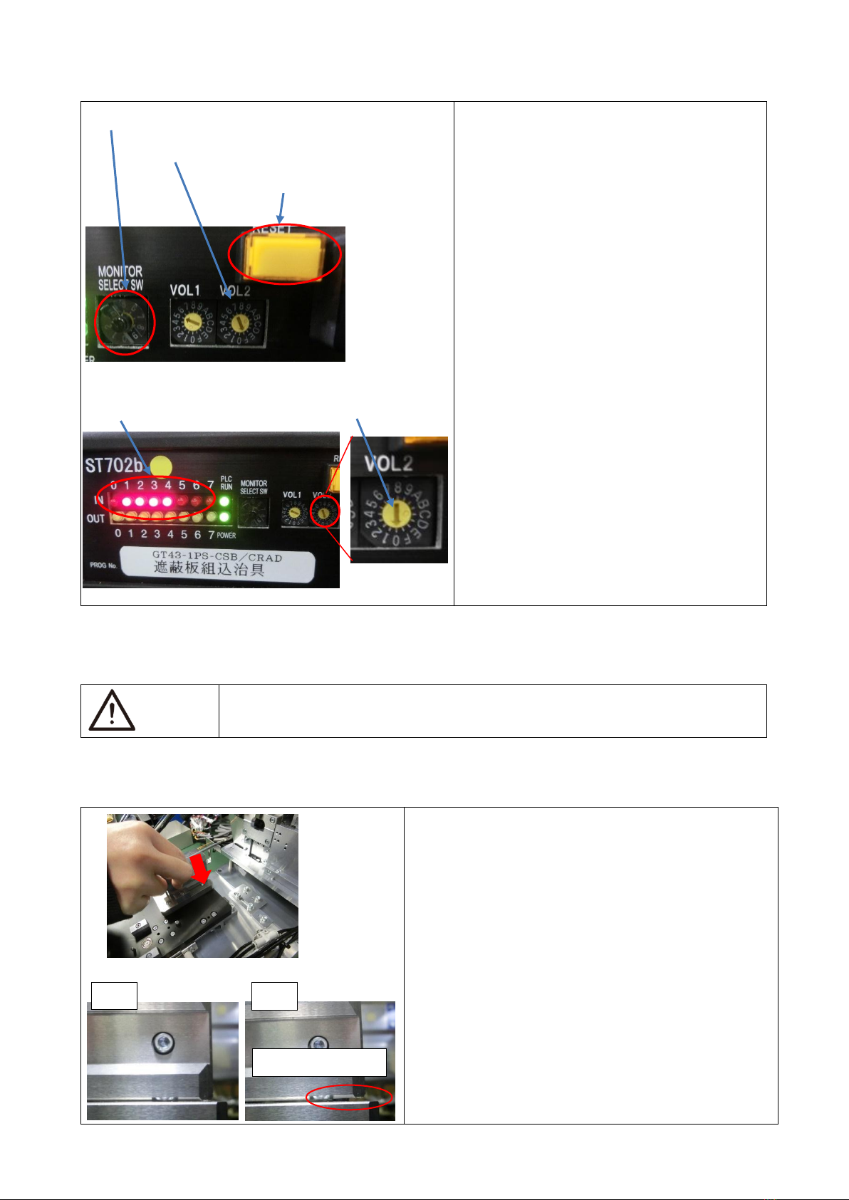
6
⑤Set the monitor select switch of the
control box for the shielding plate
assembly jig to “9”.
⑥Set the dial of the Vol.2 rotary switch of
the control box for the shielding plate
assembly jig to “F”.
⑦Press the yellow reset button.
(This operation makes the machine to be
in “shielding plate existing” mode, and the
operation is enabled.
⑧Verify that IN 1 - 4 lamps on the control
box of the shielding plate assembly jig are
lit.
⑨Set the dial of the Vol.2 rotary switch of
the control box for the shielding plate
assembly jig to “0”.
(This state means preparation is
complete.)
* If “F”+ reset is not selected, 4 times blank
feed will take place. Blank feed will result
in the shielding plate loss, and there is a
possibility that the carrier cut section will
cause a trouble.
4-2. Working method
WARNING
Be careful not to have your hand, finger, hair or clothes get caught in the moving
section of the machine.
Prepare a cable completed in the external cylinder terminal crimping process (cable is set to the cable
clamp).
Do the work according to the following procedure.
①Turn ON the power of the 2 control boxes.
②Open the finger valve of the shielding plate
assembly jig main body of the electrical
component plate, and supply air.
③Set the cable clamp (external cylinder crimping
completed product) to the base of the cable clamp
set section.
Note: Because the proximity sensor, which detects that
the cable clamp is properly set, is incorporated in
thebase section,thejigwillnotoperateif thecable
clamp is not properly set.
⑤ Set the monitor select switch to “9”.
⑥Set VOL2 rotary switch to “F”.
⑦Push the reset button.
⑨ Set to “0”.
⑧Make sure that the lamp is ON.
OK
NG
Not firmly seated.
Dec.1.2023Copyright2023HIROSEELECTRICCO.,LTD.AllRightsReserved.

7
④Press the start SW.
The shielding plate table advances and moves the
external cylinder terminal crimped product to the
home position at the shielding plate assembly
section.
Next, the shielding plate assembly jig will operate.
⑤After completion of 1 cycle, remove the cable
clamp, which completes the work.
* In case the operation is stopped by the reset button due to incorrect crimping, press the Reset button.
By pressing the Reset button, origin point return will take place.
After pressing the Reset button, dispose the defective parts in the red box.
The design is made in a way that the equipment will not operate unless the transmission sensor in the
red box is made to respond once after resetting.
4-3. Ending work
①Turn OFF the power of the 2 control boxes.
②Close the finger valve.
③Remove the waste in the shielding plate carrier cut waste receiving box.
5. CONFIRMATION OF THE QUALITY
Check each item.
Refer to the latest GT43 terminal instruction manual for the details.
5-1 Checking the shielding plate assembly dimensions
Wide and height
After completion of the shielding plate assembly
work, verify the dimensions (shape) of the 2
locations as shown in the illustration on the left
using a toolmaker’s microscope or the like.
Location
Dimension
S
Wide
5 ±0.1
X2
Height
2.855 ±0.075
P,Q<X2
How bending is
made
Visually check
inside.
5-2. Checking the dimension of the shielding plate assembly
position
Assembly position
After completion of the shielding plate assembly
work, verify the dimension of 1 location as shown
in the illustration on the left using a toolmaker’s
microscope or the like.
Location
Reference value
M
0.1 ±0.1
* Reference value is shown for M.
There is no problem if there is no interference
between the shielding plate plastic section and the
terminal plastic section and if a gap can be
observed.
(NG in case the above cannot be satisfied.)
Cross section XX (case 1)
Cross section XX (case 2)
Dec.1.2023Copyright2023HIROSEELECTRICCO.,LTD.AllRightsReserved.

8
• Make sure that the crimping barrel of the
shielding plate is covering the outer periphery of
male and female terminals.
• NG if the mating joints of the barrel is misaligned
for half of the barrel width or more or if the left and
right barrels are not contacting the terminal.
5-3. Checking the shielding plate cut off tab dimension
Cut off tab
Location
Reference value
N
Within 0.3
5-4. Appearance Inspection
Control the cut made during the crimping work to be within the level not affecting the connection
performance.
In case a cut affecting the connection performance is made, replace the crimper or the anvil etc. as
necessary.
6. SETTING METHOD AND OPERATIONAL FLOW
Setting to the operational modes below can be made by turning the dial of VOL.2 using a micro-driver or
the like.
When shipped out of the factory, dial setting is made to zero (line/auto).
Shielding plate assembly jig
VOL.2 dial
Specifications
Operational
mode
Operational details
0
Line
Auto
When the start switch is pressed,
operation will be made for 1 cycle.
1
Line
Step
Each time the start switch is pressed,
the motion will change in the order of
slide advance ⇒shielding plate
operate ⇒slide return.
2
Stand-alone
Auto
When the start switch is pressed, slide
only will operate for 1 cycle.
3
Stand-alone
Step
When the start switch is pressed, the
slide will advance, and when the start
switch is pressed again, the slide will
return.
Dec.1.2023Copyright2023HIROSEELECTRICCO.,LTD.AllRightsReserved.

9
Shielding plate cable transfer 1 set
VOL.2 dial
Specifications
Operational
mode
Operational details
0
Line
Auto
When the start switch is pressed, slide
only will operate for 1 cycle.
1
Line
Step
When the start switch is pressed, the
slide will advance, and when the start
switch is pressed again, the slide will
return.
F
–
–
* Initial position setting
* Refer to the initial position setting method for the jig at the time of newly inserting the shielding plate
as described in section 4-1 of this instruction manual.
Operational flow diagram
Seated sensor
Start SW
Pallet advance
Front edge sensor
Pallet descend
Crimping jig operation
Internal timer
Vol.1
Numeral x 0.1sec
In the case of Vol.2 0,1
In the case of Vol.2 2,3
Pallet ascend
Pallet return
Dec.1.2023Copyright2023HIROSEELECTRICCO.,LTD.AllRightsReserved.

10
7. ADJUSTMENT AND SUPPLEMENTAL SPECIFICATIONS
CAUTION
When making adjustment of this machine, be sure to make adjustment after
confirming that the quality of the previous process is satisfactory.
7-1. Adjustment of various speed controllers
Because the speed controller is adjusted to the optimum level at the time of shipment from the factory,
adjustment is basically not required.
Reference value of the control level for various speed controllers are described as a guideline.
〇Shielding plate cable transfer 1 set
Transfer cylinder forward side…2 turns release from fully closed state.
Transfer cylinder return side…2 turns release from fully closed state.
Transfer top/bottom cylinder top side…1 turn release from fully closed state.
Transfer top/bottom cylinder bottom side…1 turn release from fully closed state.
〇Shielding plate assembly jig
* When adjusting the speed controller, it will be necessary to remove the rear cover.
For that purpose, be sure to do the work while the air source and power supply are turned OFF.
The photo below is taken with the cover removed.
Terminal cut cylinder forward side…4.5 turns release from fully closed state.
Terminal cut cylinder return side…4.5 turns release from fully closed state.
Transfer top/bottom cylinder top side
speed controller
Transfer top/bottom cylinder bottom
side speed controller
Transfer cylinder forward side speed
controller.
Transfer cylinder return side speed
controller.
Terminal cut cylinder forward side
Terminal cut cylinder return side
Dec.1.2023Copyright2023HIROSEELECTRICCO.,LTD.AllRightsReserved.

11
Shielding plate cut and push cylinder top end side…6 turns release from fully closed state.
Shielding plate cut and push cylinder lower end side…6 turns release from fully closed state.
Terminal feed cylinder forward side…3 turns release from fully closed state.
Terminal feed cylinder return side…3 turns release from fully closed state.
Pilot pin cylinder…2 turns release from fully closed state
7-2. Adjustment of cable clamp transfer amount
Because the cable clamp transfer amount is adjusted to the optimum level at the time of shipment from
the factory, adjustment is basically not required.
When making fine adjustment, make fine adjustment for the protruded amount of the adjustment screw
in the photo below.
Transfer amount adjustment screw
Shielding plate cut and push cylinder
lower end side
Shielding plate cut and push cylinder
top end side
Terminal feed cylinder return side
Terminal feed cylinder forward side
Pilot pin cylinder
Dec.1.2023Copyright2023HIROSEELECTRICCO.,LTD.AllRightsReserved.

12
7-3. Control box default state
Control box display, in the case of correct origin point return, is described below.
(The displayed number will change depending on the number of the monitor select switch.)
〇Shielding plate assembly jig
* While VOL.1 dial is used for internal timer between each operation, change from “5” position, which
is the default setting, is not required.
* In the case of monitor select switch “3 - 8”, there will be no lamp lighting.
In case monitor select switch is “0”.
In case monitor select switch is “1”.
In case monitor select switch is “2”.
In case monitor select switch is “9”.
Dec.1.2023Copyright2023HIROSEELECTRICCO.,LTD.AllRightsReserved.
Table of contents
Other Hirose Cables And Connectors manuals

Hirose
Hirose DF62W Series Manual

Hirose
Hirose HIF Series User manual

Hirose
Hirose BM56G Series Instruction Manual

Hirose
Hirose EnerBee DF60 Series User manual

Hirose
Hirose BM10 Series User manual

Hirose
Hirose GT50 Series User manual

Hirose
Hirose GT16G-1S-HU User manual

Hirose
Hirose GT16GM Series User manual

Hirose
Hirose FH63 Series Manual

Hirose
Hirose EnerBee DF60 Series User manual

 User manual")
Popular Cables And Connectors manuals by other brands


Monoprice
Monoprice 14526 user manual

OUNEVA
OUNEVA VI02-0001 installation guide

Eaton
Eaton COOPER POWER SERIES installation instructions

SCHURTER
SCHURTER 4795 Series Assembly instruction

Splitvolt
Splitvolt Splitter Switch SPS 01-011 Quick start user guide

Burndy
Burndy Continental Industries ThermOweld CB-8 instructions


