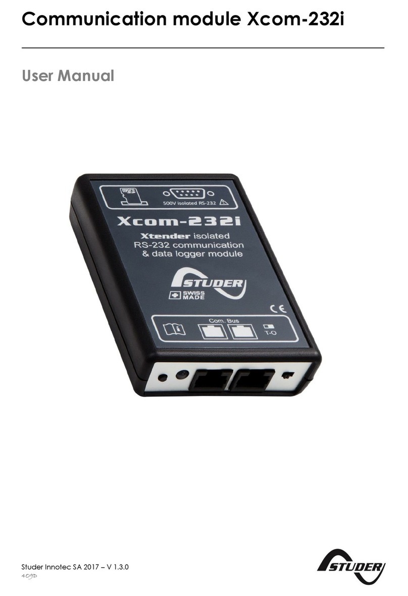
Studer Xcom-LAN User manual

Remote communication set for
Xtender systems Xcom-LAN
Quickguide
Copyright © Studer Innotec SA – V 1.2.1
4O9E7

a. Connect the Ethernet
cable between the
Ethernet gateway and
the router
b. Connect the serial cable
between the Ethernet
gateway and the
Xcom-232i
c. Connect the power
supply cable between the
Ethernet gateway and
the Xcom-232i
d. Connect the communi-
caon cable between
the Xcom-232i and the
Xtender system
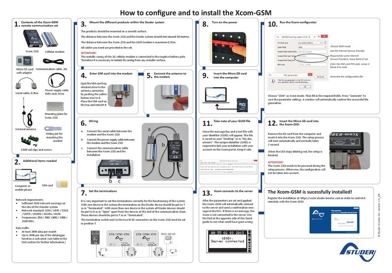
Contents of the Xcom-LAN
remote communicaon set
Micro SD card
with adapter
Router
How to congure and to install the Xcom-LAN
Insert the Micro SD card
into the computer
Addional items needed
Communicaon cable,
2m
2x 2 DIN rail clips
and screws
7.
1.
2.
Mounng plate for
the Xcom-232i
Computer or
mobile phone
15:45
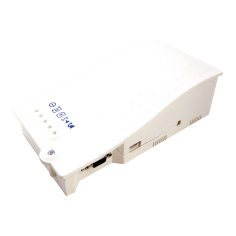
Xcom-232i Ethernet gateway
Serial cable, 0.25m
Ethernet cable, 3m
Mount the dierent products
within the Studer system
3.
The products should be mounted on a
smooth surface.
The distance between the Xcom-232i and
the Studer system should not exceed 10
meters.
The distance between the Xcom-232i and
the Ethernet gateway should not exceed
0.25 m.
All cables you need are provided in the set.
ATTENTION!
The metallic casing of the Ethernet gateway
is connected to the negave baery pole.
Therefore it is necessary to isolate its casing
from any metallic surface.
Wiring
Set the terminaons
4.
5.
It is very important to set the terminaons correctly for the funconning of the system.
With one device in the system the terminaon on the Studer device should be put to T as in "Termi-
nated". With more than one device in the system all Studer devices should be put to O as in "Open"
apart from the devices at the end of the communicaon chain. These devices should be put to T
as in "Terminated".
The terminaon switch next to the two RJ45 connectors on the Xcom-232i must be set in posion T.
Turn on the power
6.
a
b
c d
Power supply cable
RJ45-Jack, 0.5m
Internet access
Pads

How to congure and to install the Xcom-LAN
©Studer Innotec SA- version 1.2.1_EN
Insert the Micro SD card into the Xcom-232i
Xcom connects to the server
Remove the SD card
from the PC and insert
it into the Xcom-232i.
The setup process will
start automacally
and normally takes 1
second.
When the LED stops
blinking red, the setup
is nished.
ATTENTION!
The Xcom-232i needs to be powered during the setup pro-
cess. Otherwise, the conguraon will not be taken into
account.
Aer the parameters are set and applied, the Xcom–LAN
will automacally connect to the server and send a con-
rmaon message to the RCC. If there is no message, the
Xcom is not connected to the server. Use the FAQ of this
Quick guide to see what could have gone wrong.
10.
11.
It is very important to set the terminaons correctly for the funconning of the system.
With one device in the system the terminaon on the Studer device should be put to T as in "Termi-
nated". With more than one device in the system all Studer devices should be put to O as in "Open"
apart from the devices at the end of the communicaon chain. These devices should be put to T
as in "Terminated".
The terminaon switch next to the two RJ45 connectors on the Xcom-232i must be set in posion T.
Run the Xcom-congurator
8.
Choose "LAN" as Xcom mode. No other parameters are re-
quired. The gateway is already congured. Press "Generate"
to save the parameter sengs. A window will automacally
conrm the successful le generaon.
Take note of your GUID le
Close the message box and a text le with your idener
(GUID) will appear. This le is saved on your "Desktop" or in
"My documents". The unique idener (GUID) is required to
link your installaon with your account on the Xcom portal.
Keep it safe.
9.
The Xcom-LAN is successfully
installed!
Register the installaon at: hps://xcom.studer-innotec.com in
order to control it remotely with the Xcom-LAN.

FAQ
Xcom-LAN
I don’t have a DHCP server in my net-
work. What should I do?
By default, the Xcom-LAN is in DHCP/
BOOTP mode. You can set a stac IP ad-
dress by accessing the gateway.
1. Open your browser
2. Enter the default IP address in the ad-
dress bar (indicated on the back of the
gateway)
3. Enter the password (default pass-
word: xcomlan)
4. Click on "Network Sengs" in the
navigaon bar
5. Change IP conguraon from "DHCP/
BOOTP" to "Stac"
6. Set IP address, netmask, gateway and
DNS server
7. Click on "Submit"
8. Click on "Save/Restart"
My Xcom-LAN is connected to a company
network. What should I do?
The TCP port 83 may be blocked due
to security sengs. Please change the
outbound rule for this port.
My Xcom-LAN is well-congured and con-
nects to the server, but I can’t register it
with the given GUID. What should I do?
Check the Moxa’s TX counter (see Moxa
web interface -> monitor -> Async -> TxCnt).
If this counter is at zero, the Xcom’s TX line
is damaged and must be replaced. Please
contact the Studer Innotec support in
order to replace your set.
Xcom-portal
I can’t register my new installaon. What
should I do?
To register a new installaon, the installa-
on needs to be:
1. Congured correctly and in accord-
ance with the user manual.
2. Have been connected to the server at
least once.
In order to validate that the installaon has
been correctly congured, the Xcom sys-
tem info (available on the RCC connected to
the system) should indicate either Xcom-
LAN (for an installaon with Xcom -LAN) or
Xcom-GSM (for an installaon with Xcom-
GSM).
To validate that the connecon with the
installaon is well established, control that
the RCC displays the message "Server con-
nected" when turning on the installaon.
There are no datalogger les in the Data-
logger tab. What should I do?
If the installaon is new and the Micro SD
card of the Xcom-LAN/-GSM is empty, it is
normal that there are no les on the server.
To acvate the automac recovery of the
Datalogger:
1. The Xcom-LAN/-GSM needs to have a
soware version higher than 1.5.36
2. The datalogger needs to be acvated
on the Xcom-LAN/-GSM (the green
LED should be connuously lit).
3. The Xcom-LAN/-GSM needs to have a
micro SD card inserted connuously

LED states
LAN gateway LEDs
LED
name
LED
colour State Indicaon
Ready
Red
Always On Power is on and the NPort is boong up.
Blinking Indicates an IP conict, or DHCP or BOOTP server is not responding properly.
Green Always On Power is on and the NPort is funconing normally.
Blinking The NPort has been located by the NPort Administrator’s Locaon funcon.
-O Power is o, or a power error.
Link
Orange Always On 10 Mbps Ethernet connecon.
Green Always On 100 Mbps Ethernet connecon.
-O Ethernet cable is disconnected.
Tx/Rx
Orange Always On Serial port is receiving data.
Green Always On Serial port is transming data.
-O No data is being transmied or received through the serial port.
Xcom-232i LED
LED
colour State Indicaon
Red
Blinks
(Ton = 50 % | To = 50 %)
Updang process. During the Xcom-232i updang process (aer inser-
on of a MicroSD card containing the updates), the signalisaon LED
blinks in red with a cyclical rao of 50 %.
Always on Error during update or back up of the data logger. If the Xcom-232i
detects an error, the signalisaon LED is connuously red.
Blinks
(Ton = 10 % | To = 90 %)
MicroSD card full. If the Xcom-232i detects that the MicroSD card is full,
the signalisaon LED blinks in red with a cyclical rao of 10 % .
Green
Always on Data logging. When the data logging funcon is acvated, the signalisa-
on LED is green.
Blinks connuously
(Ton = 20 % | To = 80 %)
Communicaon (via RS-232 connecon). When the communicaon
via the RS-232 connecon is acve, the signalisaon LED blinks in green
with a cyclical rao of 20 %.
Blinks 2x In operaon. The signalisaon LED blinks in green twice when the Xcom-
232i is in operaon and none of the above menoned states is indicated.
Orange On 1.5s Inseron of the SD card. When inserng an SD card, the signalisaon
LED is both red and green simultaneously for 1.5 second.
If several of the three states indicated by the red LED light occur simultaneously, they will be displayed in
the following priority order:
• Update processing
• Error during updang
• MicroSD card full
If the two states indicated by the green LED light occur simultaneously, the signal indicang communicaon
via RS-232 connecon is reversed (Ton=80% |To=20%).

Legal noces
WARRANTY AND LIABILITY
Exclusion of warranty
No warranty claims will be accepted for damages
caused by handling, operaon or acons that
are not described in this manual. Damages aris-
en from the following events are not covered by
the warranty:
• Overvoltage on the device.
• Liquid in the device or oxidaon due to
condensaon.
• Damage resulng from a fall or a mechanical
shock.
• Modicaons carried out without the explicit
authorizaon of Studer Innotec SA.
• Nuts or screws parally or insuciently
ghtened during installaon or maintenance.
• Damage due to atmospheric overvoltage
(lightning).
• Damage due to transport or inappropriate
packaging.
• Disappearance of original idencaon
marks.
Disclaimer of liability
Installaon, commissioning, use and maintenance
of this device cannot be supervised by Studer
Innotec SA. For this reason, we do not accept
any liability for damages, costs or losses generated
either by an installaon that is not conforming
to the prescripons, by a defecve operaon or
by poor maintenance. The use of this device is
under the responsibility of the end-user. This
device is neither designed nor guaranteed for
the supply of life support applicaons or any
other crical applicaon with potenal risks for
human beings or for the environment. We shall
assume no liability for patent infringement or
other third party rights involved in the use of
this device.
Compability
Studer Innotec SA guarantees the compability
of the soware updates with the hardware for
one year, starng from the date of purchase. The
updates are no longer guaranteed beyond this
date and a hardware upgrade may be required.
Please contact your reseller for any addional
informaon on compability.
SAFETY PRECAUTIONS
Generalies
Carefully read all safety instrucons before pro-
ceeding with the installaon and commissioning
of the device. Failure to follow these instrucons
might constute a lethal physical danger but can
also damage the funconalies of the device.
Therefore this manual should be kept close to
the device.
For any installaon, the local and naonal
norms and regulaons in force must be strictly
followed.
Warnings
• The installaon and commissioning of the
communicaon sets must be entrusted to
skilled and qualied personnel perfectly
aware of the safety precauons and local
rules in force.
• All components connected to this device
must be conforming to the laws and regu-
laons in force. Persons without a wrien
authorizaon from Studer Innotec SA are
forbidden to do any changes, modicaons
or repairs whatsoever. Regarding authorized
modicaons and replacements, only gen-
uine components shall be used.
• This device is meant for indoor use only
and must under no circumstances be ex-
posed to rain, snow or any other humid or
dusty environment.
• If used in motor vehicles, this device must
also be protected against vibraons by
shock absorbing components.
EU DECLARATION OF CONFORMITY
The communicaon set Xcom-LAN described in
this manual meet the requirements specied in
the following EC direcves and norms:
Low Voltage Direcve (LVD) 2014/35/EU
- EN 62368-1:2014
Electromagnec Compliance (EMC) Direcve
2014/30/EU
- EN 61000-6-2:2005
- EN 61000-6-4:2007/A1:2011
Table of contents
Other Studer Conference System manuals
Popular Conference System manuals by other brands
Cisco
Cisco TelePresence MX700 reference guide
Grandstream Networks
Grandstream Networks GVC3200 Administration guide

Yealink
Yealink MeetingSpace VC500 quick start guide
Samsung
Samsung iDCS 16 System administration and special features guide
TriCom
TriCom TCR-HHR-02 Operator's manual
AVIRE
AVIRE 4G DCP installation guide
