HME SYS6700HD Specifications

SYS6700HD
Drive-Up Communication System
Operator Instructions
HME# 400G753
Rev D 3/16/18
HM ELECTRONICS, INC.
2848 Whiptail Loop, Carlsbad, CA 92010 USA
Phone: 1-800-848-4468 Fax: 858-552-0172


TABLE OF CONTENTS
INTRODUCTION ........................................................ 1
Full Duplex and Half Duplex Modes ...........................................1
SYSTEM 6700HD EQUIPMENT ............................................. 2
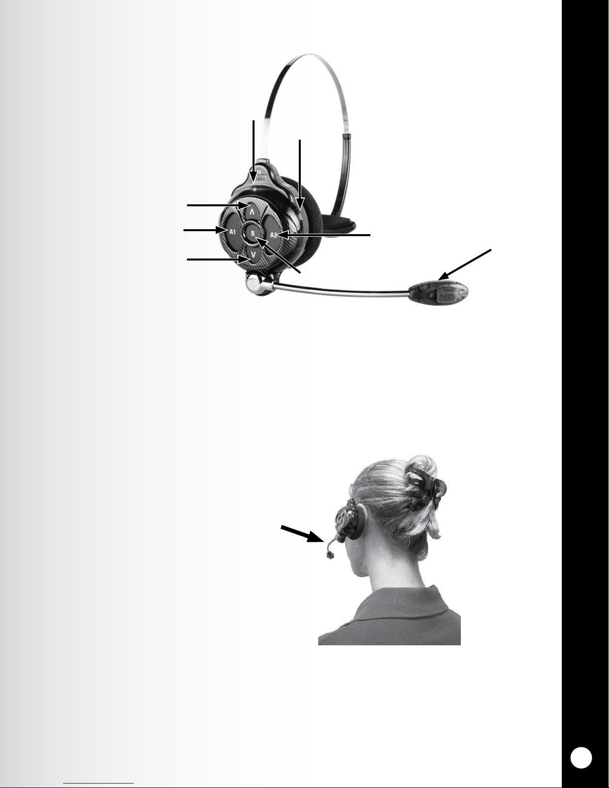
Headsets ...............................................................3
Using the Headset Controls .................................................4
Headset Modes of Operation.................................................4
Changing Language of Headset Prompts........................................5
Obtaining Headset Status ..................................................5
Headset Battery Removal and Replacement .....................................6
Battery Charger ..........................................................7
Console ................................................................8
Router .................................................................8
Base Station.............................................................9
SYSTEM 6700HD OPERATION ............................................. 10
Console ................................................................10
Remote Display ..........................................................10
Using a POS System.......................................................11
Routine Operation ........................................................12
Other Modes of Operation ..................................................17
Special Features..........................................................18
POS Answer Mode (Infor POS Only) ...........................................18
Base Station Settings ......................................................19
Register Headsets.........................................................23
Sonic Settings ...........................................................25
Store Settings............................................................26
Network Settings .........................................................31
Basic Network Settings.....................................................31
Advanced Network Settings .................................................33
Diagnostics .............................................................35
ACCESS CONTROL OF THE BASE........................................... 36
EQUIPMENT CARE AND CLEANING ......................................... 37
Handling the Equipment Properly.............................................37
Cleaning the Equipment....................................................37
TROUBLESHOOTING .................................................... 38
FCC NOTICE .......................................................... 40

FIGURES AND DIAGRAMS
Illustrations in this publication are approximate representations of the actual equipment,
and may not be exactly as the equipment appears.
HM Electronics, Inc. is not responsible for equipment malfunctions due to erroneous
translation of its installation and/or operating publications from their original English versions.
Figure 1. SYS6700HD standard equipment ...........................................2
Figure 2. Headset controls .......................................................3
Figure 3. Correct wearing of the headset .............................................3
Figure 4. Battery-removal ........................................................6
Figure 5. Batteries in charger .....................................................7
Figure 6. Console ..............................................................8
Figure 7. Router . . . . . . . . . . . . . . . . . . . . . . . . . . . . . . . . . . . . . . . . . . . . . . . . . . . . . . . . . . . . . . . 8
Figure 8. Base station front panel ..................................................9
Figure 9. Customer status display .................................................10
Figure 10. Remote Display ........................................................10
Figure 11. Remote Display Error ....................................................10
Figure 12. HME Connection Status..................................................11

INTRODUCTION
1
INTRODUCTION
The 6700HD Wireless Drive-thru Audio System is designed to deliver a clear drive-thru
conversation.
The Push-to-Talk feature is a basic headset operation that allows customer communication by
holding a headset button to talk and listen. The headset button is released to disconnect (see below).
Hands Free headset modes allow Order Takers to communicate with customers as they would in a
phone call by pressing a button once to talk to a customer at the menu. The headset automatically
disconnects when the customer drives away.
Full Duplex and Half Duplex Modes
Full Duplex:
In most Drive-Thru operations, a Menu board or Speaker Post consists of a Microphone to hear the
customer talk and a Speaker so the customer can listen.
When your Base Station is congured in Full Duplex mode, the Microphone and Speaker can
transmit audio at the same time like a telephone call. This is benecial for increasing the ability to
understand a customer and immediately respond without delay.
Half Duplex:
Half Duplex works like a Walkie Talkie. To speak to the customer, press the headset Abutton. To
listen to a customer, release the Abutton.
In this unique conguration, the stall or order point consists of only a single speaker.
This single speaker is used to both speak to and listen to the customer. But because there is only one
speaker, the Order Taker can’t speak and listen simultaneously as performed in Full Duplex mode.

SYSTEM 6700HD EQUIPMENT
2
OPTIONAL EQUIPMENT
Equipment Model Number
All-In-One Headset..................HS6200
Battery for Headset .................BAT51
Battery Charger . . . . . . . . . . . . . . . . . . . . AC50
Headset Earmuff ...................None
Ceiling Speaker ....................MM100
Microphone .......................DM4
Speaker ..........................SP10
Vehicle Detector Board...............VDB102R
Vehicle Detector Loop (underground) ....VDL100
Low-Prole Speaker .................SP2500LP
Remote Antenna Kit (6 ft cable) ........ANT20-6
Remote Antenna Kit (30 ft cable) .......ANT20-30
Manager’s Speaker with Volume Control ..GM2500
SYSTEM 6700HD EQUIPMENT
The 6700HD is an audio system primarily
for use at drive-up service facilities. It will
allow up to four service operators wearing
wireless headsets/belt-pacs to serve up to
64 customers at outside drive-up service
stalls. A drive-thru service lane can be used
in place of one drive-up stall.
The system can be integrated with the Infor
POS system or operate in a stand-alone
mode.
The equipment shown below is standard
with the 6700HD system. Optional
equipment can be ordered from your local
dealer.
NOTE:
Equipment quantities vary,
depending on individual store needs
at time of purchase.
Additional equipment can be ordered
from the list below.
Figure 1. SYS6700HD standard equipment

SYSTEM 6700HD EQUIPMENT
3
Headsets
Features and Controls
Wearing the Headset
●Wear the headset with the microphone on your right or left side next to your mouth.
●Adjust the headband and microphone boom as needed.
Figure 3. Correct wearing of the headset
Hold microphone boom here to adjust
microphone position
Figure 2. Headset controls
Transmit light
Channel “A2” button
Channel “A1” button
Channel “B” button
Power
button
Power light
Volume-up button
Volume-down button

SYSTEM 6700HD EQUIPMENT
4
Using the Headset Controls
The control buttons will activate when pressed rmly. Use your ngertips, not your ngernails, to press
the buttons.
Power On/Off
●Power On — Press and release the Power button.
A voice message in the headset will say “headset #, battery full/half/low” and both the power
light and the transmit light will ash red. After a short time, the power light will change to steady
green for Lane 1 and the transmit light will go off. A voice message in the earpiece will then say
“Lane 1 (or 2).”
●Power Off — Press and hold the Power button for about two seconds. A voice message in the
earpiece will say “headset off,” and the power light will go off.
Volume Up/Down
●Volume-Up Adjustment — Press and release the volume-up Λbutton. Each time you press
the button you will hear a higher pitch beep in the earpiece as the volume increases. When you
reach maximum volume, you will hear a high-pitched double beep. If you press and hold the
volume-up Λbutton, you will hear repeating beeps, increasing in pitch until the volume reaches
maximum. Then you will hear high-pitched double beeps repeating until you release the volume-
up Λbutton.
●Volume-Down Adjustment — Press and release the volume-down Vbutton. Each time you
press the button you will hear a lower pitch beep in the earpiece as the volume decreases. When
you reach minimum volume, you will hear a low-pitched double beep. If you press and hold
the volume-down Vbutton, you will hear repeating beeps, decreasing in pitch until the volume
reaches minimum. Then you will hear low-pitched double beeps repeating until you release the
volume-down Vbutton.
Headset Modes of Operation
Hands-Free (HF) Mode
●With the headset powered off, press and hold the volume-up Λand Bbuttons while you press and
release the Power button to turn it on in the HF mode. The headset will remember this setting.
●Touch and release the A1 or A2 button to speak and listen to the customer hands free.
●Touch and release the A1 or A2 button to unlatch the headset.
●Touch and release the A1 or A2 button if you want to latch the headset, in order to communicate
with the customer again.
●Use the volume-up Λand down Vbuttons to adjust the customer’s voice level in your headset if
necessary.
●If a customer drives away from the speaker post or menu board, the headset unlatches
automatically.

SYSTEM 6700HD EQUIPMENT
5
NOTE:
Only one operator at a time
can use the auto-hands-free
feature, and this feature must
also be enabled on the base
station.
If a headset is turned off
while in the AHF mode, it will
automatically be reset for its
previous operating mode.
Auto-Hands-Free (AHF) Mode
●With the headset powered off, press and hold the volume-up Λand A1 buttons while you press
and release the Power button to turn it on in the AHF mode.
●When a car arrives at the menu, the headset will automatically latch on and you can speak and
listen to the customer without pressing any buttons.
●Touch and release the A1, A2 or Bbutton to end communication with the customer.
●Touch and release the A1 or A2 button if you want to speak to the customer again.
●Use the volume-up Λand down Vbuttons to adjust the customer’s voice level in your headset if
necessary.
●If a customer drives away from the speaker post or menu board, the headset will unlatch
automatically.
Push-To-Talk (PTT) Mode
●With the headset power off, press and hold the volume-down Vand Bbuttons while you press and
release the Power button to turn it on in the PTT mode. The headset will remember this setting.
●Touch and hold the A1 or A2 button to speak to the customer. Release to stop speaking to the
customer (full duplex) or to listen to the customer (half duplex). Use the volume-up Λand down V
buttons to adjust the customer’s voice level in your headset if necessary.
Changing Language of Headset Prompts
To change the language of the prompts heard in the headset from English to Spanish to French and back
to English, with the headset power off, press and hold the volume-down Vbutton and the A1 button
while you press the Power button. Each time you do this, the language of the headset prompts will
change as the power goes on. When the headset is turned off and on again, the prompts will remain in
the last language set.
To change to the next language, with the headset powered off, again press and hold the volume-down V
button and the A1 button while you press the Power button.
Obtaining Headset Status
To obtain headset status, with its power off, press and hold the volume-down V button and the A2
button while you press the Power button. You will hear the status message in the headset when the
power goes on.

SYSTEM 6700HD EQUIPMENT
6
Headset Battery Removal and Replacement
To change batteries
When a battery becomes weak, a voice in the headset will say “Change battery.” When this happens,
press the battery-release button and slide the battery out of the headset as shown in Figure 5.
To replace batteries
When replacing a battery in the headset, place the end of the battery with the metal contacts into the
headset, in the same position as the battery you removed. Press the battery carefully in until it snaps in
place.
Figure 4. Battery-removal
Battery-release button (blue)
Battery

SYSTEM 6700HD EQUIPMENT
7
Battery Charger
Up to four batteries can be charged in the charger at the same time. Charging time is approximately 2.5
hours. The battery status lights next to each charging port are explained below. Up to six fully charged
batteries can be stored in the battery storage ports.
Procedure:
Insert batteries in the charging ports for charging. The batteries can only go into the charging ports one
way. If they do not go in easily, turn them around. DO NOT force them. Push each battery down into
a port until it snaps in place, to be sure it makes full contact.
Battery Status Lights:
●A yellow light stays on steady next to each charging port while the port is empty.
●Insert a battery in one of the four charging ports until it clicks in place.
●A red light will stay on next to a battery while it is charging.
●A green light will go on next to a battery when it is fully charged.
●If a yellow light is on next to a battery in a charging port, it means the charge failed. If this
happens: (1) Be sure the battery is pushed all the way into the port until it snaps into place
to make contact. (2) Try charging in a different port. If it charges this time, the rst charging
port may be defective. If the battery does not charge in the second port, replace it with another
battery.
●Store up to four fully charged batteries in the storage ports.
Figure 5. Batteries in charger

SYSTEM 6700HD EQUIPMENT
8
Console
The Console is a stationary control panel used to display messages and
provide manual control for any selected base station in the system.
●The SELECT STALL and 0-9 keys are used to manually select a stall
number.
●The SELECT STATION and 1-4 keys are used to select Base Station
assignment.
●Assign or un-assign a base station to drive-thru lane service only.
●The MONITOR ONLY key’s function has been removed. If you press
this key, you will get an error. This error has no effect on the system.
●The SELECT STALL and DRIVE THRU keys are used in combination
to connect a base station to the drive-thru lane.
●The ENTER key is used to process a command request and move to
the next eld.
Router
The Router is a switcher unit that allows an operator to be switched to any of up to sixteen stalls
connected to its respective Base Station.
The Router is powered by an AC adapter, which is available for inputs of 115 or 230VAC.
Figure 6. Console
Figure 7. Router

SYSTEM 6700HD EQUIPMENT
9
Base Station
All functions of the audio system are channeled through the base station. It is the electronic heart of
the SYS6700HD.
Figure 8. Base station front panel
●The menu-select buttons are used to make selections from the menu on the display
screen.
●The Help button can be pushed to obtain information needed in case of problems with
the base station settings.
●The Back button can be pushed to go back to the previous menu display, saving any
setting changes or exiting a display screen when no changes have been made.
●The activity indicators light up as follows:
¾A1 lights up when the Abutton is pushed on any headset registered to this
base.
¾B1 lights up when the Bbutton is pushed on any headset registered to this
base.
¾The Car Icon lights up when a stall or drive-thru is connected.
●When both of the cabinet latches, on top of the cabinet are pressed down at the same
time, the cabinet can be opened by pulling forward and down.
●The reset switch is used to perform a soft restart of the base station. It is located in a
small hole on the right side of the base station. To press the reset switch, carefully push
a small pointed object, such as an unfolded paper clip, into the hole.

SYSTEM 6700HD OPERATION
10
SYSTEM 6700HD OPERATION
Console
Headset button “A1” and “A2” are for connecting to
a stall or drive-thru to communicate with a customer.
Button “B” will disconnect the stall or drive-thru,
ending communication with a customer. During the
operation, the following customer status is displayed
on the Console, as shown in Figure 9.
1= Base address number 1 through 4
2= The number of customers waiting in queue to be served
3= The number of the drive-up stall to which an operator is connected, “READY” when the
system is in the idle mode; the operator is not connected to a stall, but the system is ready
4= “CONNECTED” when the operator is connected to a customer
Remote Display
Mode 1 – Number in Queue and Wait Time
5 = The number of customers waiting in queue to be served
6 = Wait time for the rst car in the queue
Mode 2 – Base Station and Connection Status
7 = Base Station 3 and customer 1
8 = Base Station 3 and error (see table)
In addition to the routine status, the following error information
may appear on Remote Displays:
Figure 9. Customer status display
Figure 10. Remote Display
Figure 11. Remote Display Error
EWhen Communicator button “A” has been pushed, indicates an empty
queue (ex: 3. E)
bIndicates busy (ex: 1. b)
tIndicates terminate (ex: 3. t)
E. Indicates an error message (ex: E.01)
NOTE:
If an error message appears, call
HME at 1-800-848-4468.

SYSTEM 6700HD OPERATION
11
Using a POS System
1. See the HME Connection Status Grid displaying the base stations, stalls (or lanes) and the
employees currently connected in the 6700HD system.
2. View and use the POS Order Selection screen as an additional console to:
●Connect to a stall
●Enable or disable the base station’s drive-thru only mode.
NOTE: It is not necessary to be in POS mode to:
●See the HME queue
●See the HME connection status
●Assign or de-assign a base to an employee
●Connect to a stall
●Enable or disable a base in DT Only mode.
For more information, consult the Infor POS System documentation.
Figure 12. HME Connection Status

SYSTEM 6700HD OPERATION
12
Routine Operation
To operate the SYS6700HD, follow the instructions below.
If there is no customer waiting, when the rst new customer presses a call button, you will hear a call
button tone (double beep) in your headset. You may also hear a rst-in-queue tone (single, repeating
beep) from a nearby ceiling speaker.
Press button “A1” or “A2” on your headset to speak and listen to the customer.
You will hear “Stall _#_” in your headset.
You can have a normal conversation with the customer, like talking on a telephone. Speak in a normal
voice. Do not shout.
When you have nished, press button “B” to disconnect from the customer.
If no other customer is waiting, there will be no sound in your headset.
If another customer is waiting to be served, you will hear a call-button tone (double beep) in your
headset, repeating every 4 seconds until you press the “A1” or “A2” button again to connect with the
next customer. If there are more customers waiting, you will automatically be alerted for the customer
who pushed a call button rst.
Drive-Thru Lane: If your store has a drive-thru lane, drive-thru customers will have priority over
customers in drive-up stalls. They will automatically be placed ahead of any drive-up stalls. When a
drive-thru customer arrives, a single tone will be heard in the headset of the rst available operator.
When the operator presses headset button “A1” or “A2”, “Drive-thru” will be heard in their headset.
The drive-thru communication channel will be opened. After the drive-thru customer has been served,
button “B” must again be pressed to disconnect from the drive-thru lane.
To connect to a stall or drive-thru, press button “A1” or
“A2” on your headset
To disconnect from a stall or drive-thru, press button “B”
on your headset.
Repeat the operation as long as customers are waiting in the
queue. e system automatically places each new customer
at the end of the queue when they press their call button.
NOTE:
If you press button “A1” or “A2”
when no customer is waiting in the
queue, you will hear “Empty queue”
in your headset.

SYSTEM 6700HD OPERATION
13
EXAMPLES:
The following are examples of typical operating scenarios in routine drive-up service operations. They
describe what you will normally hear and see using SYS6700HD equipment, and provide step-by-step
instructions telling you exactly what to do in each situation.
●System is IDLE. No customers have pressed any call buttons.
Headset : No sound in headset
Ceiling speaker : No sound from ceiling speaker
Console display :
Remote display :
● First customer presses call button (at stall 3), and is automatically placed rst in the queue.
Headset : Call-button tone (double beep)
Ceiling speaker : First-in-queue tone (single, repeating beep)
Console display :
Remote display :
Press button “A1” or “A2” on your headset
to connect to the rst customer (at stall 3).
Headset : Voice says “stall three”
Ceiling speaker : No sound from ceiling speaker
Console display :
Remote display :
Talk and listen to the customer at stall 3.
NOTE:
The Remote Display alternates
between showing the number
of customers in queue and
the total time for the current
customer.

SYSTEM 6700HD OPERATION
14
●Second customer presses call button (at stall 12), and is automatically
placed next in the queue.
Headset : No new call-button tone will sound to interrupt the conversation
with your current customer.
Ceiling speaker : Repeating tone
Console display :
Remote display :
●Third customer presses call button (at stall 7), and is automatically placed next in the queue.
Headset : No new call-button tone will sound to interrupt the conversation
with your current customer.
Ceiling speaker : Repeating tone
Console display :
Remote display :
Press button “B” on your headset to disconnect from the current
customer (at stall 3).
Headset : Call-button tone (double beep) will repeat at 4-second intervals until you press button
“A1” or “A2” again to connect with the next customer in the queue.
Ceiling speaker : Repeating tone
Console display :
Remote display :

SYSTEM 6700HD OPERATION
15
Press button “A1” or “A2” on your headset to connect to the next customer
in the queue (at stall 12).
Headset : Voice says “stall twelve”
Ceiling speaker : Repeating tone
Console display :
Remote display :
Talk and listen to the customer at stall 12.
Press button “B” on your headset to disconnect from the current customer
(at stall 12).
Headset : Call-button tone (double beep) will repeat at 4-second intervals until you press button
“A1” or “A2” again to connect with the next customer in the queue.
Ceiling speaker : Repeating tone
Console display :
Remote display :
Press button “A1” or “A2” on your headset to connect to the next customer
in the queue (at stall 7).
Headset : Voice says “stall seven”
Ceiling speaker : No sound from ceiling speaker
Console display :
Remote display :
Talk and listen to the customer at stall 7.

SYSTEM 6700HD OPERATION
16
Press button “B” on your headset to disconnect from the current
customer (at stall 7).
●System is IDLE again.
Headset : No sound in headset
Ceiling speaker : No sound from ceiling speaker
Console display :
Remote display :
System will remain idle until another customer presses a call button.
●Customer arrives in drive-thru lane, and is automatically placed to the head
of the drive-up queue.
Headset : Drive-thru tone (single tone)
Ceiling speaker : Single, repeating
Console display :
Remote display :
Press button “A1” or “A2” on your headset to connect to the drive-thru
customer (in the drive-thru lane).
Headset : Voice says “drive-thru”
Ceiling speaker : No sound from ceiling speaker
Console display :
Remote display :
Talk and listen to the drive-thru customer.
Press button “B” on your headset when you are ready to disconnect from the
drive-thru customer.
NOTE:
The system will automatically
disconnect if a customer drives
away from the speaker post.
Other manuals for SYS6700HD
1
Table of contents
Other HME Conference System manuals

HME
HME EOS HD User manual

HME
HME IC300 User manual

HME
HME SYS6700HD User manual

HME
HME ION IQ Instruction Manual

HME
HME NEXEO HDX User manual

HME
HME Communicator COM6000 User manual

HME
HME Clear-Com HelixNet Partyline User manual

HME
HME EOS HD User manual

HME
HME NEXEO HDX User manual

HME
HME Wireless 6400 User manual