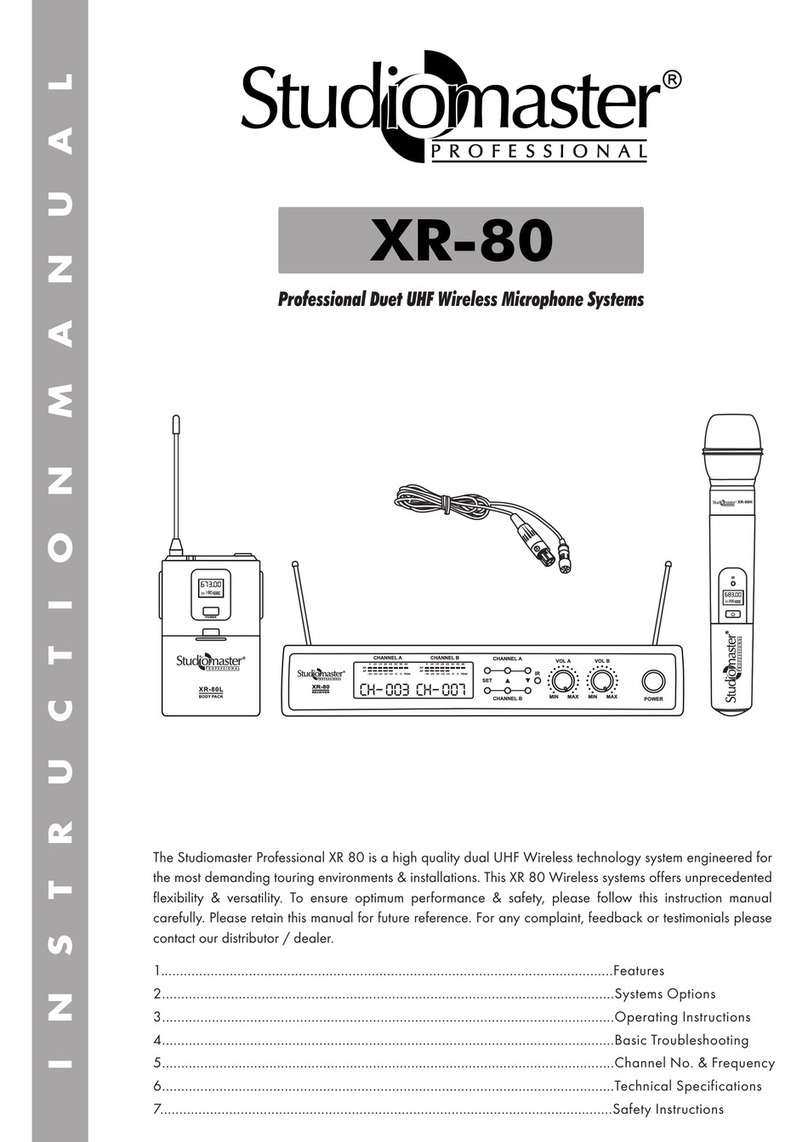
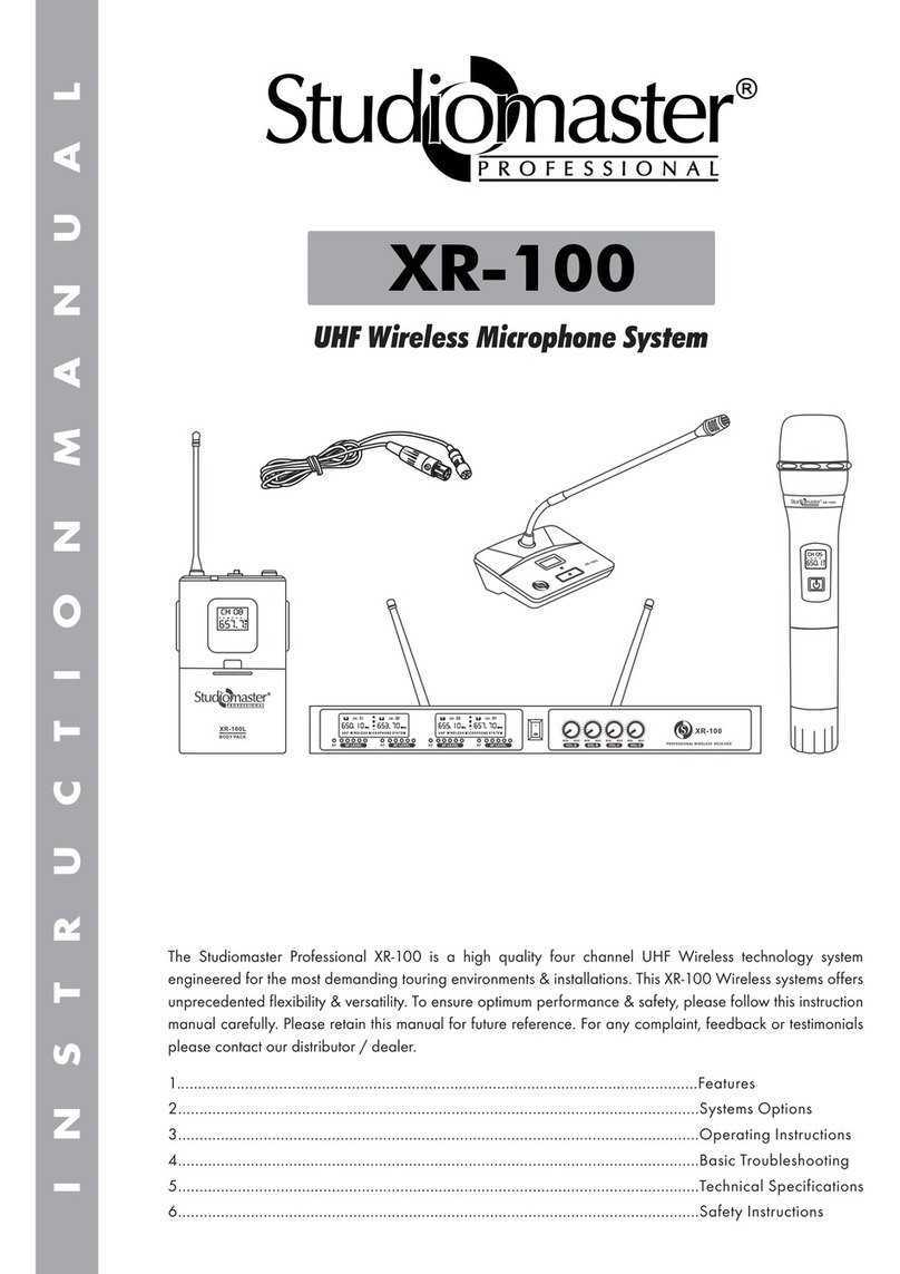
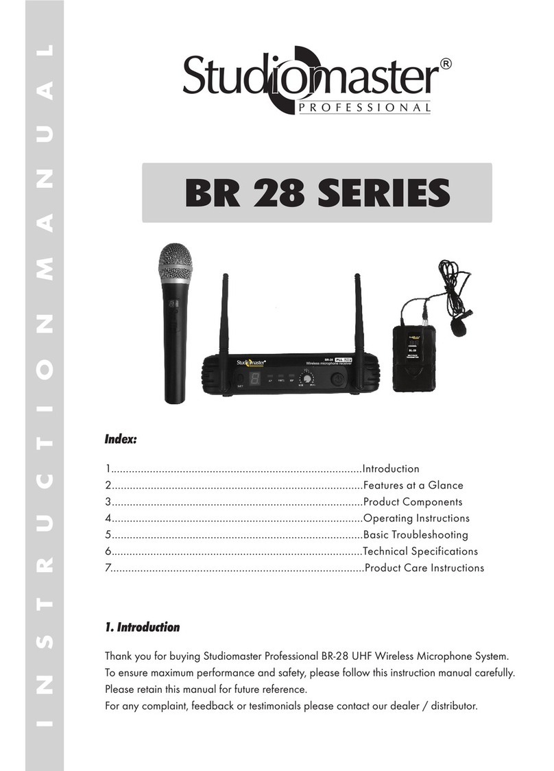
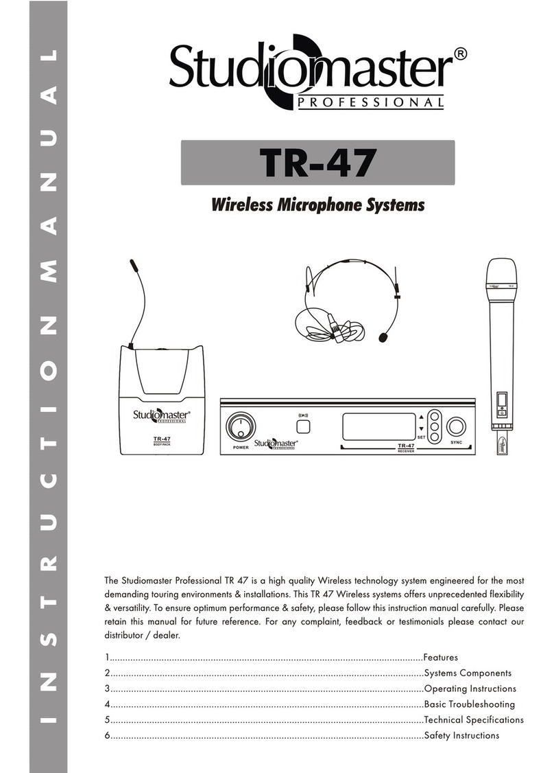
Studiomaster BR 12 SERIES User manual

BR 12 SERIES
Introduction
Thank you for purchasing Studiomaster Professional wireless microphone.
To ensure maximum performance and safety, please follow this instruction manual carefully.
Please retain this manual for future reference.
For any complaint, feedback or testimonials please contact your Studiomaster Dealer.
Index:
1..........................................................................................Introduction.
2..........................................................................................Features at a Glance.
3..........................................................................................Product Components.
4..........................................................................................Operating Instructions.
5..........................................................................................Basic Troubleshooting.
6..........................................................................................Technical Specifications.
7..........................................................................................Product Care Instructions.

Features at a Glance.
Product Components.
Receiver Features. The Front and Rear Panel
Operating Instructions.
The BR 12 Series from Studiomaster Professional is a Top wireless technology system engineered for the most
demanding touring environments and installations. This series of UHF wireless systems offer unprecedented
flexibility and versatility.
• UHF band frequency by Quartz locked controlled.
• Compact ,Light Weight receiver
• LED indicator [Power, Diversity (A-B), Peak] & telescopic antenna
• Extended dynamic range • Special circuit design to eliminate microphone switch ON/OFF nose.
• True Diversity Reception Mode • UHF hi-band range 720-865 MHZ
• Unbalanced 6.3mm jack & balanced XLR Output connectors. • Audio bandwidth 50Hz-15KHz
• Low battery LED indicator on the microphone. • Microphone operates with a 9 V Battery (6-8 hrs)
• Receiver operates on 12V DC through an AC adaptor.
• Output volume control on the front panel.
1. Power Switch: Turns receiver power on/off.
2. Power ON Indicator: This red light glows when the receiver is plugged into an electrical outlet and
switched on. It indicates that the receiver is on.
3. Diversity Signal Indicators: The green light of diversity A/B glows when RF (radio frequency) signals are
received from the transmitter. When A light is glowing, the channel A is being used, when B light is
glowing the channel B is being used.
4. Audio level Indicator: Audio level indicator of receiver glows according to the volume of the transmitter
when talking or singing into the microphone.
5. Volume control: Rotate this Knob to increase or decrease the volume of the receiver output.
6. Model Number of the receiver.
7. Antenna
8. Balanced Output XLR Male Socket: For obtaining balanced audio output through a 3-pin female XLR plug
9. Unbalanced Output JACK Socket: For obtaining unbalanced audio output of high or low levels, than a
¼'' phono jack
10. DC Input Socket: For connecting the DC Plug of a 12V adaptor.
POWER AF OUT
UHF
Wireless Receiver
+
12.15V_ _ _ 12
BR-12
Professional Wireless Microphone
READY
POWER
ANTENNA
VOL A
2
7
10
6
5
8
4
9
3
• Receiver x 1 • Wireless Handheld Microphone or Lapel Microphone x1 • Audio Cable x 1
• AC Power adapter for Receiver x 1 • Battery (9 Volt) x 1 • Instruction Manual x 1
2

UHF
STDBY
OFF
ON
LO
BAT
LEVEL
BL-12
Wireless Transmitter
OPEN
1
3
2
5
4
USAGE TIPS
Handheld Transmitter Features.
Body Pack Transmitter Features.
Receiver Indicator
not lighting.
Make sure AC adapter is securely plugged into electrical outlet and into
POWER connector on rear panel of receiver. Make sure AC electrical
outlet works and is supplying proper voltage.
Basic Troubleshooting.
SolutionIssue
Please check gain levels.
Please check cable connections.
Audio light glows but
no Sound.
Distortion or unwanted
noise bursts
Remove nearby sources of RF interference (CD players, computers, cell
phones, digital effects, in-ear monitor systems, etc.)
Reduce transmitter gain. Replace transmitter battery.
If using multiple systems, change the channel of one of the active systems.
Avoid using two systems with the same frequency at the same place;
please separate them at least by 200 meters.
1. Grille: It protects the Diaphragm from
damages. Also acts as an effective wind
& pop filter.
2. Power ON/OFF & Mute SWITCH: Put
the switch to ON position, the indicator
shines for a moment. Put the switch to
MUTE, allows muting the microphone audio.
3. Low Battery LED indicator: This LED will glow continuously if the battery voltage is low thereby indicating
the need to replace the 9V battery by a new battery.
4. Battery Cover: Unscrew for access to the 9V battery and gain control.
1. Microphone Head (Lavalier)
2. Low Battery LED indicator: This LED will glow continuously
if the battery voltage is low thereby indicating the need to
replace the 9V batter by a new battery.
3. Power ON/OFF & Mute SWITCH: Put the switch to ON
position, the indicator shines for a moment.
Put the switch to MUTE, allows muting the microphone audio.
4. Input connector: Allows you to connect to the Lavalier.
5. Audio Gain Control: Provides audio level adjustment to
accommodate various input signal strengths.
- Make sure you can always see the receiver antenna from the transmitter position.
- Keep the distance from transmitter to receiver as short as possible
- Avoid placing the receiver antennas near metal surfaces and obstruction.
- Perform a walk through before performance or presentation. If dead spots are found,
adjust location of receiver. If dead spots remain mark spots and avoid.
ON
LOW
BATT
MUTE
OFF
BM-12
14
3
2
2 3

- Keep the wireless receiver in a good location to ensure good signal strength.
- Do not drop the Microphone, Transmitter or Receiver; this could severely damage the product.
- Please keep this product away from direct sunshine & Rain.
- Please keep this product away from heavy magnetic or electromagnetic fields, it could affect product
performance.
- Please switch off when removing the Batteries.
- Please remove the batteries / power supply when the product is not being used for a long time.
- Do not open any of the components yourself, for repairs please get in touch with your retailer.
Technical Specifications.
Receiver Specifications:
Transmitter Specifications:
Over All Specifications:
Product Care Instructions
Carrier Frequency Range
Modulation Mode
Frequency response
S/N ratio
Audio dynamic range
T.H.D
Operating range
720-865 MHz , UHF band
FM
50Hz – 15 KHz
>85dB
>100dB
<1%
50m/150ft (under typical conditions)
Power requirements
Signal/Noise Ratio
Channel Rejection
Image & spurious Rejection
Audio Output level
Receiving Sensitivity
12-15V DC , 300mA
> 85dB
> 70dB
> 70dB
0 - + 300mV
-105dBm
Power requirements
Nominal Current Drain
RF Output
Microphone element
Max Deviation
Spurious Emission
9V Alkaline Battery
< 40mA
> 13dBm
Unidirectional dynamic microphone
+ 30KHz
> 55dB
Table of contents
Other Studiomaster Microphone System manuals
Popular Microphone System manuals by other brands

Sennheiser
Sennheiser Evolution Wireless Digital EW-DX EM 2 quick guide

Alpha Technologies
Alpha Technologies RBMS Installation & operation manual

SWIT Electronics Co.,LTD.
SWIT Electronics Co.,LTD. CW-S150 user manual

Shure
Shure UA844 user guide

Panasonic
Panasonic SHFX70 - DVD HOME THEATER WIRELESS SYSTEM operating instructions

Pyle
Pyle PDWM5000 user manual


