Suaoki 3000 User manual

Wireless Cadence Bike Computer
User Manual
EN DE FR IT ES JP

CONTENTS
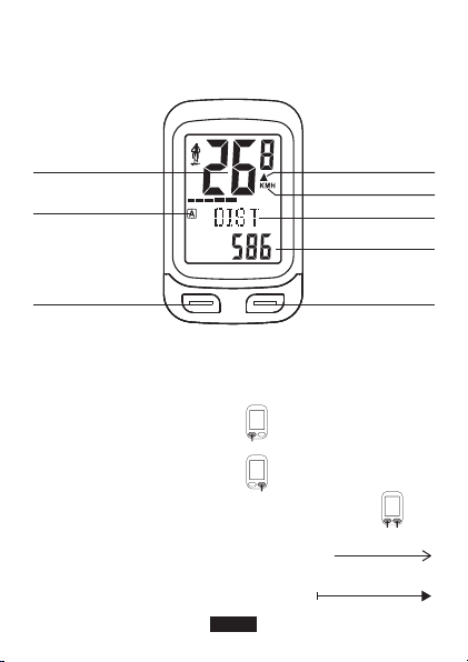
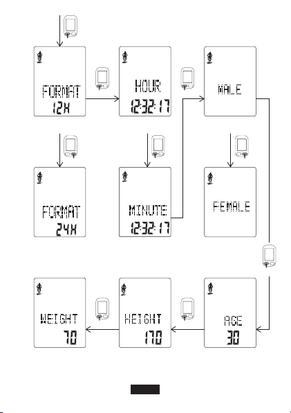
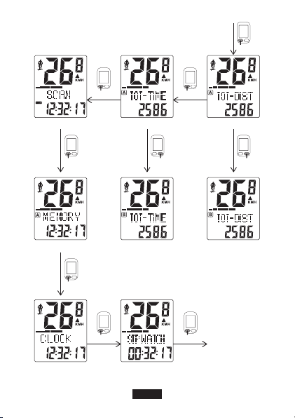
Operation Diagram········1-11
English·························12-19
Deutsch·······················20-27
Français······················28-35
Español·······················44-51
Italiano························36-43
日本語························52-59

Diagrams and Flow Charts
Real-time Speed
Bike A/B
Mode Button
Pace Arrow ▲▼
Indicates whether the
current speed is faster
(▲) or slower (▼) than
the average speed.
Speed Unit
Set Button
Data
Function
Diagram Explained
1. Press MODE button(left button)
2. Press SET button(right button)
3. Press both MODE and SET button(left and right button)
4. You need to follow the sequence of the flow chart
5. You can jump into this operation in any stages
EN-1
MODE
MODE+SET
SET

MODE MODE
MODE
SET SET SET
MODE MODE
Diagram 1: Setting Flow
Display Language
English
Unit Setting
KMH
Dual Bike Memory*
Bicycle A
Chinese MPH Bicycle B
Total Ride Time* Total Distance* Wheel Circumference*
EN-2

MODE
MODE
MODE
SET SET
Clock Format
12H
Time
(Hour:Minute:Second)
Gender
Male
Clock Format
24H
Female
MODE
MODE MODE
MODE
Weight(Unit:KG) Height(Unit:CM) Age
EN-3
MINUTE

Diagram 2: Pairing
EN-4
Paring Done Pairing Failed

Diagram 3: Operation Flow
EN-5
Temperature(℃/℉)
CALORIE (Bike A)
CALORIE (Bike B) Carbon Offset (Bike B)
Carbon Offset (Bike A)
Cadence
Avg Cadence
MAX Cadence
SETSETSET
SET
MODE MODE
MODE

EN-6
Clock Stopwatch
SCAN
Memory Total Distance (Bike B)Total Ride Time(Bike B)
Total Ride Time(Bike A) Total Distance (Bike A)
···
MODE
MODEMODE
MODE MODE
MODE
MODE
SETSET

EN-7
Ride Time (Bike A)Distance (Bike A)
Distance (Bike B) Ride Time (Bike B)
AVG Speed (Bike A)
AVG Speed (Bike B)
Max Speed (Bike A)Max Speed (Bike B)
SET
SET
SETSET
MODE MODE
MODE

MODE+SET
Diagram 4: Power-saving Function
Diagram 5: Backlight Display
Diagram 6: Installation
4 mins of inactivity
ON OFF
computer sensor
EN-8
1. Install Batteries

3. Install Cadence
Magnet
4. Install Speed
and Cadence
Sensor
5. Done
2. Install Speed
Magnet
EN-9

Diagram 7: Transmission Range
Diagram 8: Wheel Circumference
3m Max
≤3mm
EN-10
≤3mm

Diagram 9: Package Contents
EN-11
User Manual
Cadence Sensor
Speed Sensor
Wireless Cadence Bike Computer
User Manual

EN-12
Thank you for choosing Suaoki.
This product is a simple wireless bike computer that tracks cadence,
speed, distance and time. It is compact, lightweight and comes with
everything you need. This device is ideal for cyclists who like to know
all this data, monitor their progress or optimize their training.
Please read this manual thoroughly before use and keep it for future
reference.
Install Battery to the Computer Unit
[Refer to Diagram 6]
Step 1
Insert a coin to the dent of the battery cover and then rotate it
counter-clockwise to open battery cover.
Step 2
Note:
When using the computer unit for the first time, make sure to
remove the insulation pad inserted between the battery and the
computer unit.
Put in the button cell battery with the positive side facing upward. Put
the battery cover back and rotate it clockwise to close the battery
cover. Setting menu opens automatically when the battery is inserted.
Set the Computer Unit
[Refer to Diagram 1]
Pres SET button for selection. Press MODE button to confirm the
choice and move on to the next value. You can configure following
values: display language, units (KMH/MILE), bike A/B, wheel
circumference, total distance, total ride time, clock format 12H/24H,
clock time and gender, age, height, weight.
Note
* 1 DualBike Memory
This computer unit could record two sets of data, one set for Bicycle A,
another set for Bicycle B.

* 2 Wheel Circumference
You can find the wheel circumference (L) of your bike in the Appendix.
Usually, ETRTO or tire size is indicated on the side of the tire. You could
also measure tire circumference by doing a wheel roll out:
[Refer to Diagram 8]
With the tires under proper pressure, place the valve stem at the
bottom. Mark the spot on the floor and with the rider’s weight on the
bike, roll exactly one wheel revolution in a straight line (until the valve
comes around again to the button). Mark where the valve stem is and
measure the distance between the two markers.
*3 Total Distance & Total Ride Time
Data would be deleted once you replace this device’s battery. In this
case, you could enter the total distance and time manually, so you
don’t have to start from nothing.
Pairing
[Refer to Diagram 2]
Pair the computer unit with the sensor
Step 1: When you are done with setting, the bike computer will enter
the pairing mode automatically. At this stage, you need to install
battery to the sensor. When using the sensor for the first time, make
sure to remove the insulation pad from the sensor.
Step 2: Place the bike computer and the sensor together. The distance
between computer unit and sensor should not exceed 3m.
Step 3: When the pairing is successful, the LCD screen would display
“PAIR OK” and then speed would display on screen. When the pairing
is not successful, the speed display would be “--”. [as shown in
Diagram 2]
Note:
Remember to pair the computer unit with the sensor every time
when you replace the computer unit or the sensor with a new battery.
EN-13

EN-14
Install the device on bike
Install the bracket and computer unit
Step 1: Attach the rubber slice on handlebar/stem.
Step 2: Stick the bracket on the handlebar/stem.
Step 3: Hang the O-ring on one side of the bracket. Go around the
handle bar or stem. After that, secure the O-ring to the other side of the
bracket. For more stability, you could fix the bracket using cable ties.
Now, the bracket should be properly installed. [refer to instructional
video]
Step 4: Set the computer into the notch of the bracket (NW/SE
direction), push on gently and clockwise to fix the computer unit.
Note:
You can loosen the four screws on the bracket to change its
orientation.
Install the sensor and magnets
[Refer to Diagram 6]
Step 1: Install Speed Magnet
Installed the speed magnet on the bicycle spoke. Secure the magnet
and tighten the screw.
Step 2: Install Cadence Magnet.
Attach the cadence magnet to the bike crank arm with straps.
Step 3: Install Speed and Cadence Sensor
Attach the speed and cadence sensor to the bike chainstay with cable
ties. When installing speed sensor, the side marked with ‘sensor’ need
to face towards the wheel direction and stay close to the speed
magnet. When installing the cadence sensor, you need to make sure
the cadence sensor face towards and stay close to the the cadence
magnet.
Step 4: Adjust the position of computer unit, sensor and magnets.
Tighten the cable ties and cut off the excessive part of the ties.

EN-15
Transmission Range
① The max effective data transmission distance between the computer
unit and sensor is 3-5m.
② The max effective data transmission distance between the sensor
and magnet is 1.5-3mm.
Operation Flow
[Refer to Diagram 3]
Press SET button for selection. Press MODE button to confirm the
choice and move on.
Cadence
Measured in rpm (current cadence, AVG cadence, MAX cadence)
Calorie Consumption (CALORIE)
Estimated burned calorie according to the trip distance. Measured in
KCAL. Note that this data could be displayed only when trip distance is
over 3km.
Carbon Offset (CO2)
Estimated reduced carbon dioxide emissions according to the trip
distance. Measured in KG. Note that this data could be displayed only
when trip distance is over 3km.
Temperature (TEMP)
Displayed in preferred unit-°C or °F. Press the SET button to choose.
Total Distance (TOT-DIST)
Total ride distance from last reset. You can reset this value by taking the
battery out of its compartment. Data would be deleted once you
replace this device’s battery and then could enter the total ride
distance manually.
Total Ride Time (TOT-TIME)
Total trip time from last reset. You can reset this value by taking the
battery our of its compartment. Data would be deleted once you
replace this device’s battery and then could enter the total trip time
manually.

EN-16
Scan
Automatic rotation of selected values: Ride Time, Distance, Average
Speed, Max Speed and Total Distance
Memory
The memory saves data recorded in last 7 days. Press SET button to
switch among the days. Display data as follow: DIST, RIDETIME,
AVG-S, MAX-S, CALORIE and CO
2
(rotate automatically).
Clock
The clock is displayed in chosen format (12H or 24H)
Stopwatch
Press set button to start and then press set button again to stop. Hold
set button for 2 seconds to reset the numbers.
Count Range: 00:00:00~59M:59S:99~99H59M59S
Distance (DIST)
Measured in km or mile (according the settings)
Ride Time (RIDETIME)
Format HH:MM:SS
AVG Speed (AVG-S)
Measured in km/h or mph (according the settings)
Max Speed (MAX-S)
Measured in km/h or mph (according the settings)
How to enter into setting menu?
Switch to ‘Clock’ mode. Long press mode button/left button. Then the
computer unit would enter into the setting menu.
How to clear operation data?
You can reset the following values all together: RIDETIME, DST, AV-S
and MX-S, CO
2,
CALORIE. Long press SET button. On the display
screen, ‘RESET’ will flash for twice and then the value reset is done.

EN-17
Note:
TOT-DIST, MEMORY and CLOCK cannot be reset.
Backlight
In any MODE and hold [SET]+[MODE], shows the LIGHT ON or LIGHT
OFF, when in LIGHT ON mode, press any key and the backlight turn on
3 seconds.
Q & A
Q1: Opened the back-light, and data display is blurry.
A: This happens due to low power. You need to replace the battery. The
data stored in this device would be cleared when you replace this
device with new batteries. Before removing the batteries, note down
the current total distance and total ride time. You can enter the data
manually when you set the bike computer.
Q2: No data display when testing cadence.
A: You cannot not test the cadence alone without testing the speed.
For example, rotating the crank arm with bike unmoved cannot get any
results. This device could not display anything.
Q3: Black/dark display
A: This happens because device was exposed to direct sunlight for too
long. You need to cool down this device by moving it to shaded area.
Q4: LCD display responds slowly
A: Very low temperature. Move to warmer place.
Q5: Clear display, but no data
A: This happens due to power supply issues, such as low battery
capacity, or battery inserted upside down. In this case, simply replace
the battery or insert the battery correctly.
Q6: No real-time speed display or the displayed data is
wrong
A: There are several possible ways to look at and solve this problem:

EN-18
1. Computer unit still in the setting phase. You need to set the
computer and then move on to the operating phase.
2. The distance between the computer unit and sensor, between
sensor and magnet exceeds effective transmission range. Or, the side
marked with ‘sensor’ is not in the right angle. You need to relocate the
parts to the required position and angle.
3. Wrong wheel circumference setting. Enter into the setting menu.
Reset wheel circumference.
4. Low power level. Battery installed in the sensor need to be replaced
5. High voltage may cause this product to malfunction. Please move it
away from any source of high voltage.
Product Specifications
Battery(Computer&Sensor)
Sensor Signal transmission
Working Temperature
Dimensions
Weight
Model
2.4GHz
0°C-50°C (32°F-122°F)
6.3*4*2cm(2.5*1.6*0.8 inch)
30g
3000
Approx. 1 year (when
using this device 1
hour/day)
Battery Life
Battery Material Li-MnO2
Battery Model No.
Voltage
Battery Capacity
Power
CR2032
3.0V
210mAh
0.63W
Table of contents
Languages:
Other Suaoki Bicycle Accessories manuals