manuals.online logo
Brands
  1. Home
  2. •
  3. Brands
  4. •
  5. Sub-Zero
  6. •
  7. Refrigerator
  8. •
  9. Sub-Zero 601R User manual

Sub-Zero 601R User manual

Other manuals for 601R

6

This manual suits for next models

11

Other Sub-Zero Refrigerator manuals

Sub-Zero CBIC-18FI Guide

Sub-Zero

Sub-Zero CBIC-18FI Guide

Sub-Zero IC-27R User manual

Sub-Zero

Sub-Zero IC-27R User manual

Sub-Zero BI-36R User manual

Sub-Zero

Sub-Zero BI-36R User manual

Sub-Zero Designer Series User manual

Sub-Zero

Sub-Zero Designer Series User manual

Sub-Zero 601F User manual

Sub-Zero

Sub-Zero 601F User manual

Sub-Zero Classic Series User manual

Sub-Zero

Sub-Zero Classic Series User manual

Sub-Zero IT-30FI User manual

Sub-Zero

Sub-Zero IT-30FI User manual

Sub-Zero 500 Series User manual

Sub-Zero

Sub-Zero 500 Series User manual

Sub-Zero 648PRO User manual

Sub-Zero

Sub-Zero 648PRO User manual

Sub-Zero 542 User manual

Sub-Zero

Sub-Zero 542 User manual

Sub-Zero DEC3650FI/R User manual

Sub-Zero

Sub-Zero DEC3650FI/R User manual

Sub-Zero ICBIC-18FI User manual

Sub-Zero

Sub-Zero ICBIC-18FI User manual

Sub-Zero 700TR User manual

Sub-Zero

Sub-Zero 700TR User manual

Sub-Zero PRO 48 User manual

Sub-Zero

Sub-Zero PRO 48 User manual

Sub-Zero 600 Series Operating manual

Sub-Zero

Sub-Zero 600 Series Operating manual

Sub-Zero BI-36R User manual

Sub-Zero

Sub-Zero BI-36R User manual

Sub-Zero PRO 48 User manual

Sub-Zero

Sub-Zero PRO 48 User manual

Sub-Zero BI-42S Assembly instructions

Sub-Zero

Sub-Zero BI-42S Assembly instructions

Sub-Zero ICBBI Series Service manual

Sub-Zero

Sub-Zero ICBBI Series Service manual

Sub-Zero ICBBI-36R Guide

Sub-Zero

Sub-Zero ICBBI-36R Guide

Sub-Zero BI-30UG Operating manual

Sub-Zero

Sub-Zero BI-30UG Operating manual

Sub-Zero UC-24RO Assembly instructions

Sub-Zero

Sub-Zero UC-24RO Assembly instructions

Sub-Zero IT30RRH User manual

Sub-Zero

Sub-Zero IT30RRH User manual

Sub-Zero UC24CILH User manual

Sub-Zero

Sub-Zero UC24CILH User manual

Popular Refrigerator manuals by other brands

Frigidaire FRS26TS7DW2 Use & care manual

Frigidaire

Frigidaire FRS26TS7DW2 Use & care manual

Fisher Scientific 10ECEEFSA manual

Fisher Scientific

Fisher Scientific 10ECEEFSA manual

Summit FF22BDRSS user manual

Summit

Summit FF22BDRSS user manual

Frigidaire FFRU17B2QWE use & care

Frigidaire

Frigidaire FFRU17B2QWE use & care

Hotpoint ENBGH 19xxx FW operating instructions

Hotpoint

Hotpoint ENBGH 19xxx FW operating instructions

Hitachi R-SG28KPH instruction manual

Hitachi

Hitachi R-SG28KPH instruction manual

Dometic RMH 7390 L operating instructions

Dometic

Dometic RMH 7390 L operating instructions

AEG S71700TSW0 user manual

AEG

AEG S71700TSW0 user manual

Electrolux ENB3669 Instruction book

Electrolux

Electrolux ENB3669 Instruction book

Electrolux ERN 2930 Instruction book

Electrolux

Electrolux ERN 2930 Instruction book

Beko GNE 60520 X user manual

Beko

Beko GNE 60520 X user manual

Jenn-Air JUR248LBES00 Use & care guide

Jenn-Air

Jenn-Air JUR248LBES00 Use & care guide

Dometic RGE 4000 Installation and operating manual

Dometic

Dometic RGE 4000 Installation and operating manual

Dometic L-0191B Brochure & specs

Dometic

Dometic L-0191B Brochure & specs

LG LRBP1031W - 10 Cu. Ft. Cabinet Depth Bottom Freezer... owner's guide

LG

LG LRBP1031W - 10 Cu. Ft. Cabinet Depth Bottom Freezer... owner's guide

Daewoo RN-33 Series user manual

Daewoo

Daewoo RN-33 Series user manual

Haier RF-8888-174 Service manual

Haier

Haier RF-8888-174 Service manual

Blaupunkt 5CK2 Series user manual

Blaupunkt

Blaupunkt 5CK2 Series user manual

manuals.online logo
manuals.online logoBrands
  • About & Mission
  • Contact us
  • Privacy Policy
  • Terms and Conditions

Copyright 2025 Manuals.Online. All Rights Reserved.

INSTALLATION INSTRUCTIONS
CONTENTS
Installatio_ lIe_oirn_ e_ da tio_ s
InatallaI o[_ Spe_,"ifica Iiio_s
Installatio_ hStlrllctiolla
Fira_t,_ed IPnwA Installatio_
Ow_da y IPnwA Inslallalio_
Co_epleting tire h_stallalio[_
Service InfO_lrn_atio_
3
4
8
12
20
23
Specifications are subject to change without notice.
Check our website, subzero.com, for the most
up-to-date specifications.
As Vou fellow these inStlrUCtiel}s veu vlill
i%otice WAt@HIHG a_d CAUTK:)H Sylr_,bela,
Ttis blocked i_fo_eatio;_ is imlpertalr_t for tt_e
aaIe a_sd e_fJio eIl_t iIIstalIatio[_ Of S_Ib ZeI'o
equipH_etat T_e/'e al'e two types of petel_tia_
Naza_'ds tibet _av oaeu_ d_ ng instaIlatio_
signaIs a si!_atio n whele mil_e_ _iI_I_.!I_V e_'
Pl'e¢!l!I t taIIM/I® maV !!9!! !! VG!! d ° !!I!:
state_ a Isaza[i tibet may cause se_ie_._s
!n]_,_r_ e_ tea_!_ !_ p_eca_s_!ens a[e sot
Iolewed.
Anotl_e_ _eetlrlete _e _euld lil_e to ide_AifV is
IMPOBY_HT HOYE: TI_is higfhlights i_fe_lrea
tien tibet is espesiaIly ireIewaiit to e IIH'elbIem
fLree i_stallatie_
SUB-ZERO @is aregistered trademark of Sub Zero Freezer Company, Inc.
BUlLT_H iNSTALLATiON RECOMMENDATIONS
I M $"TA L LA"T I O M RECOMMENDATIONS
The importance of the installation of the
Sub-Zero B@lt-ln unit cannot be overempha-
sized. Installation should be done by a
qualified installer,
Before you begin the installation process, it
is recommended that you read this entire
Installation Instructions book. There are key
details that you should take special care to
observe during the installation, By reading
these instructions carefully, you will make the
installation process easier, problem-free and,
most importantly, safe.
Any questions or probJems about the
instaJJation shouJd be directed to your
Sub-Zero deaJer or the Sub-Zero Customer
Service Department at 800-222-7820 or e_maiJ
[email protected]. You can aJso
visit our website at subzero.com.
TOOLS AND MA'IERIALS REQUIRED
The following is a list of tools and materials
that should be available for proper installation.
Phillips screwdriver set
Slotted screwdriver set
Torx drive screwdriver set
4' (1.2 mt of 1/4" copper tubing and saddle
valve for the water line--part #4200880
(do not use self-piercing valvest
Copper tubing cutter
Level--2' 66 mt and 4' (1.2 mt recom-
mended
Appliance Dolly able to support 700 Ibs
(317 kgt and adequate manpower to
handle the weight of the unit
Various sized pliers
Wrench set
Allen wrench set
5/16" hex bolt nut driver
Crescent wrenches
Cordless drill and assorted drill bits
Masonite, plywood01/s" pressed fiberboard,
cardboard or other suitable material to
protect finished flooring
Appropriate materials to cover and protect
the home and its furnishings during instal-
lation
/"_/ I//_eteI's s_liess ot ses_4, se s>e_i_e 3
BUlLTo_N UNSTALLATUON SPECUFUCATUONS
INSTALLATION SPECUFUCATUONS
Make sure that the actual equipment that was
shipped to you matches the design you are
expecting to install. The Sub-Zero Built-in Hine
offers the following design aHternafives--
framed, oveday and stainHess steeH modeHs.
Each of these design options has specific
installation requirements, which means it is
vitaH that the unit match your pHanning and
space needs. Before you begin the installation
process, check the exact model number you
need against the model number on the
shipping carton.
if the unit you receive does not match your
requirements, contact your Sub-Zero dealer.
SIdlE pR, EPARA_I ION
Make sure that the finished rough opening
where the Builtdn unit is to be installed is
properly prepared. Refer to the Overall Dimen-
sions and Installation Specifications for your
specific model on the following pages. These
specifications are identical for each of the
design alternatives--whether your model is
framed, overlay or stainless steel. Make sure
that the rough opening dimensions, door
swing clearance, electrical service and
plumbing are correct for the model you are
about to instdk
If you are installing Built-In units side by side,
a separating filler strip is recommended. Add
the filler strip width to the finished rough
opening dimension. Complete the installation
with the Anchoring Kit (part #4200900}, see
page 21.
IMPORTANT NOTE: To operate properly, the
door must open a minimum of 90 °. Use a
minimum 3" (76) filler in corner installations to
assure a 90 ° door opening. Allow enough clear-
ance in front of the unit for full door swing.
IMPORTANT NOTE: Make sure the floor under
the unit is level with the surrounding finished
floor.
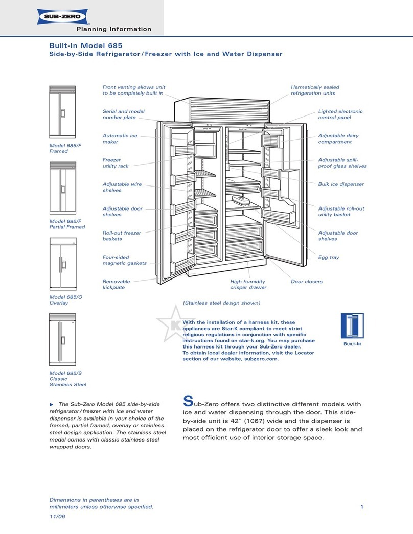
BUILT-IN INSTALLATION SPECIFICATIONS
OVI:]RA D 4ENS ONS
All ReFrigerator I All Freezer Models
36"
(914)
73"
(1854) 73"
,_ (1854)
36"_
94
W/odel 601 Ill Model 601RG
Aft Reft iqet ntor All f lef_ _get otor
vvitTt Glass Door
Width 36" (914} Width 96" (914)
Height 79" (1854} Height 73" (1854}
Depth 24" (610) Depth 24" (610)
Illustrations shown in stainless steel design.
73"
(1854)
36"
94
Model 601F
All F/eezer
Width 36" (914)
Height 73" (1854)
Depth 24" (610}
]
24"_
(610)
ALL REFRIGERATOR
ALL FREEZER
Model 601R
Mod÷l (¢01RG
All Refr_gelotot
vvi GMss Door
Model 601F
AI! ft'eezel"
INSA IATION SPEC:IFIC:AIONS
All ReFrigerator I All Freezer Models
Models 601R and 601RG will not require the
water lir}e oorlr}eotiorL
Din_ensions are for finished rough openings.
Door swir}g olearar}ces are based or}
stainless steel door and handle dirnensior_s,
I ii EXTEND
24" J'i WATERLINE
(610) i APPROX 36=(914)
ROUGH /FROM BACK WALL
IODPEi/NG (6olFONLY)_ji.'SHUT"OFF
VALVE
TOP VIEW
3/8"(10)
_U _ ExFR_[_IEo N
\\90'
237/8"
(606)
BEHIND
FRAME
361/16"
(916)
/d>ss s>e;f ,
351/2" (902)
ROUGH OPENING WIDTH
723/4" (1848)
ROUGH OPENING
HEIGHT TO
FINISHED
FLOORING
LOCATE ELECTRICAL
723/4" (1848)
MINIMUM HEIGHT
REQUIRED TO
FINISHED
FLOORING
(LEVELERS IN)
WITHIN ENTIRE SHADED AREA
LOCATE WATER SUPPLY
WITHIN BOTTOM SHADED
AREA ONLY (801F ONLY)
24" _ 6"
_ I (610) 1(152)
3"
11" _ (7i)
(279)
FRONT VIEW
BUIL%IN INSTALLATION SPECIFICATIONS
OVER-AND-
UNDER
l\4od_,l (-Fl I
Model 111 'I ®
Wit Glair;r; f-_oof
Model 650
Model £50G
vvilt Gla;>;> Door
OVt:RALL [ hENS ONS
Over-and-Under Models
30"_
(762)
84"
(2134)
84"
(2134)
_ 36" _
(914) --/31%-
[vqlodel 611 Model 611G Model 650 Model 650G
vvitf GMss Door vvitf Glass Door
Width 30" (762} Width 30" (762} Width 36" (914} Width 36" (914}
Height 84" (2138} Height 84" (2138} Height 84" (2138} Height 84" (2138}
Depth 24" (610} Depth 24" (610} Depth 24" (610} Depth 24" (610}
Illustrations shown in stainless steel design.
84"
(2134)
_ 24"_
(61o)
3/8.(10)
FRAME
EXTENSION
90
237/8 ``
(606)
BEHIND
FRAME
H,
INSTAIoLAT ON SPEC F CA-IIONS
Over-and-Under Models
Model G11
A} Rough Opening Width 29112" (74g)
I1_¢)Min Door Clearance 301/s '' (765}
Mo@l 611G
A} Rough Opening Width 291/2" (74g)
I1:¢}Min Door Clearance 301/8" (765}
Model 650
A} Rough Opening Width 351/2 '' (902)
I1:¢)Min Door Clearance 361/1s '' (916}
Mo@l ¢_50G
A} Rough Opening Width 35112" (902)
IB) Min Door Clearance 361/1s '' (916}
Dimensions are for finished rough openings,
Door swing clearances are based or}
stainless steel door and handle dimensions.
oRiiiiHG EXTEND
: WATER LINE
, APPROX 36" (914)
ii_ FROM BACK WALL
iij'
_ SHUT-OFF
ii VALVE
TOP VIEW
83" (2108)
MIN HEIGHT
REQUIRED TO
FINISHED
FLOORING
(LEVELERS IN)
(152)
LOCATE ELECTRICAL
WITHIN SHADED AREA
A
ROUGH OPENING WIDTH
751/2 ''
(1918)
LOCATE WATER SUPPLY
WITHIN SHADED AREA
3"
(76)
(457) _ (152)
l FRONT VIEW
833/4" (2127)
ROUGH OPENING
HEIGHT TO
FINISHED
FLOORING WITH
STANDARD
11" (279) GRILLE
BUILT-IN INSTALLATION SPECIFICATIONS
OVf[RALL D /_ENS C)Nf_
Side-by-Side Models
_ 36" _
(914) 42"
(1067)
_ 42" _
(1067)
[vllod_A 061 [vllodel 042 Mod_A {;;85
lce I VY_ er Dispe si l
Width 96" (914} Width 42" (10(}7} Width 42" (1067}
Height 84" (2198} Height 84" (2198} Height 84" (2198}
Depth 24" (610) Depth 24" (610) Depth 24" (610)
_ 48" _
(1219)
Model 692
Width 48" (1219)
Height 84"(2138)
Depth 24" (610)
84"
(2134)
_ 24"_
(610)
Model 695
lce I V/Y_AerDispe_ _ir} _
Width 48" (1219}
Height 84" (2198}
Depth 24" (610}
Illustrations shown in stainless steel design.
NSALIATION SPEC F C_ ONS
Side-by-Side Models
[d/od el 661
A} Rough Opening Width 351/2" (902)
B} Min Door Clearance 203/4 '' (527)
[vqlod el 642
A} Rough Opening Width 411/2" (1054)
B) Min Door Clearance 259/16 '' (649)
[d/od el 685
A} Rough Opening Width 411/2" (1054)
B} Min Door Clearance 259/16" (649)
[vqlod el 632
A} Rough Opening Width 471/2" (1207)
B) Min Door Clearance 291/4" (743}
[d/od el 695
A} Rough Opening Width 471/2" (1207)
B} Min Door Clearance 291/4" (743}
Dimensions are for finished rough openings.
Door swir}g clearar}ces are based or}
stainless steel door and handle dimensions.
/d>ss s>e;[
24" iJ
j, EXTEND
(610) ,:i/ WATERLINE
ROUGH _ APPROX35"(914)
SHUT-OFF
,i:i VALVE
TOP VIEW
83" (2108) 751/2"
MIN HEIGHT (1918)
REQUIRED TO
FINISHED
FLOORING
(LEVELERS IN)
(152)
LOCATE ELECTRICAL
WITHIN SHADED AREA
A
ROUGH OPENING WIDTH
LOCATE WATER SUPPLY
WITHIN SHADED AREA
3"
(76) 18" 6"
1 I_ (457)_1 (152)
I,_), I
l FRONTVIEW
833/4" (2127)
ROUGH OPENING
HEIGHT TO
FINISHED
FLOORING WITH
STANDARD
11" (279) GRILLE
SIDE-BY-SIDE
Model 661
Model 642
Model 685
lee /YY_,ter Di_persiq
IVlodel 632
IVledel 695
Ice / ViToter Disper si tq
_I 3/8"(1 }
FRAME
EXTENSION
237_ "
(606)
BEHIND
FRAME
BUlL%_M iNSTALLATiON iNSTRUCTiONS
ELECTRICAL REQUIREMENTS PLUMBING REQUIREMENTS
A 115VAC, 60 Hz, 15 amp circuit breaker and
ebctrbaJ sup@y are required. A separate
circuit, servicing onJy this ap@iance, is
required.
AU Sub-Zero B@tdn modeb are equipped with
a power sup@y cord with a 3-prong grounding
@ug, which must be @ugged into a mating
3-prong grounding4ype waU receptacb. FoUow
the National Electrical Code and local codes
and ordinances when installing the receptacb.
For location of the electrical supply, refer to the
Installation Specifications illustration for your
specific model on pages 5-X
IMPORTANT NOTE: A ground fault circuit
interrupter (GF@) is not recommended and
may cause interruption of operation.
The O_@÷t r_'_st be ¢he_l(ed by a qualified
deet_id_} to be s_e tha_ il ibm"wi_÷d with
For BuiMn models with an automatic ice
maker, rough in the water supply line. Connect
a %" OD copper line to the house supply. Use
an easily accessible shut-off valve between the
water supply and the unit. This valve is usually
placed about 6" (152) from the compression
fitting. Do not use self-piercing valves. A
saddle valve kit (part # 420088@ is available
from your Sub-Zero deabr.
The water line should be routed up through
the floor within 1/2" (13) from the back wall and
no higher than 3" (76) off the floor. If the water
supply is brought in from behind the unit,
route the water line through the back wail, no
more than 3" (7@ from the floor. Regardless of
the routing, allow 3' (1 m} of excess copper
tubing to remain outside the wall or floor for
easy connection to the unit. For location of the
water sup@y, refer to the Installation Specifica-
tions illustration for your specific model on
pages 5-7.
A line filter is required when water conditions
have a high sediment content. The ice maker
operates on water pressure of 20 psi (1.4 bart
to 100 psi (&9 barL
A reverse osmosis system can be used,
provided there is a consistent water pressure
of 20 psi (1.4 bart to 100 psi (6.9 bart supplied
to the water valve at aii times.
IMPORTANT NOTE: in some cases a reverse
osmosis water filter system may not be able to
maintain the minimum water pressure consis-
tently.
Good water is important for high quality ice.
it is not recommended that the ice maker be
connected to a softened water supply. Water
softener chemicals, such as salt from a
malfunctioning softener, can damage the ice
maker mold and lead to poor ice quality. If a
softened water supply cannot be avoided, it is
important that the water softener be weii main-
tained and operating properly.
BUILT-iN iNSTALLATiONiNSTRUCTiONS
UNPACK THE UNiT GRILLE REMOVAL
Uncrate the unit, remove its wood base and
discard the shipping bolts that hold the wood
base to the bottom of the unit, Remove all
packing materials and tape.
IMPORTANT NOTE: Do not discard the
MckpJate, anti-tip bJocMng kit and hardware,
These items wHJ be needed for instaHafion,
Retract the front leveling legs to allow you to
move the unit more easily during installation,
You will extend the leveling legs when the unit
is in its final position to reduce the possibility
of the unit tipping forward.
Remove the drain pan from the base of the
unit to avoid damage to the drain pan, and
allow for proper placement of the appliance
dolly,
while mevi!°_g _Jrsit_
In order to prevent damage to the grille and to
access the power cord, the top grille assembly
should be removed prior to moving the unit.
Models 611, 611(3,650, 650(3,661,642, 685,
632 and 696--framed arid stainless steel:
Remove three counter-sunk grille screws at the
bottom of the grille and cut the red nylon
shipping strap. NOTE: Grille screws are
accessed with door(s) open. Then tilt the grille
forward and release the springs from behind
the grille, Refer to illustration 1 below,
Models 601R, 601R(3 arid 601FJfrariled arid
overlay: Remove the two black screws in the
lowest louver of the grille, Tilt the bottom of
the grille out and away, It will release from the
top of the grille, Refer to illustration 2 below,
Models 601R, 601RG arid 6OlFJstairiiess
steel: The lower grille snaps out by pulling
forward on the bottom of the grille.
Models 611, 611G, 650, 650G, 661,642, 665,
632 arid 695JOVeJ'Jay: First, remove the inner
grille panel assembly as shown in illustration 3
below, Lift up, then pull out at the bottom, pull
the top section down and out of the top key
slot, Remove the five mounting screws that
hold the outer grille panel assembly to the top
compartment, Refer to illustration 4,
Screws /_k _
(insidedoor)____
k/rer ari }{!
Par_elAssembly
_h_s 4
BUIL%IN INSTALLATION INSTRUCTIONS
AM"['I-"['IP BLOCKING KIT POSITION THE UNIT
To p_eve_%_ the lll!t from tippi_g fe!waid
mist be seelred ! place witl_ a_} a_lislip
!
bleeIi_g de!ice:
Prot{_÷t anv :!_ished f!ooring before
movillg the _.ll_it ilte plaee. A!l Built÷Ir_
i _Oile!s ®ie iq/ipl}el with rillei s) sO vii
@ti eiiil ! riiie _t111 iiil illt/itslacii
If there is a solid soffit above the unit with
clearance between the unit and the soffit of 1""
(2B) or less, you won't need to block the unit.
Refer to illustration B below. For installations
with clearances of more than 1" (25), you must
block the unit with the anti-tip blocking kit
(wood block and hardware) provided.
Locate and mark two wall studs against the
wall where the Built-in unit will be installed.
Then locate the proper height to Near the unit.
The space between the unit top and the
bottom of the wood block must not be more
than 1/4"' (6}.
Position the wood block over the unit and use
the screws and 'L' brackets to lock it in place.
Make sure the screws extend a minimum of
7/s" (22) into each of the two wall studs. The
wood block must be positioned securely and
must extend at least 3" (76) over the unit. Refer
to illustration 6 below.
Shut off power to the wail outlet. Plug the
power supply cord into the 15 amp grounded
outlet and roll the unit into position under the
wood block or soffit. Using the front and rear
leveling legs, raise the unit until it makes
contact with the wood block. See Level the
Unit, page 11.
iMPORTANT NOTE: If possible, keep door(s)
dosed on the unit until it is properly anchored.
iMPORTANT NOTE: If for any reason the unit
has been laid on its back or side, you must
allow the unit to stand upright for a minimum
of 24 hours before connecting power.
dppk_g Ie_wa_6 the f_o_t k+velk_g !÷gs
m_st beir_ coK_act Wit_'l the floo_.
'0