EnglishDeutsch
 logo
Brands
  1. Home
  2. •
  3. Brands
  4. •
  5. Sub-Zero
  6. •
  7. Refrigerator
  8. •
  9. Sub-Zero 700 Series User manual

Sub-Zero 700 Series User manual

Other manuals for 700 Series

3

Other Sub-Zero Refrigerator manuals

Sub-Zero 700 Series User manual

Sub-Zero

Sub-Zero 700 Series User manual

Sub-Zero New Designer Series Guide

Sub-Zero

Sub-Zero New Designer Series Guide

Sub-Zero BI-42SD Assembly instructions

Sub-Zero

Sub-Zero BI-42SD Assembly instructions

Sub-Zero BI-36U/S/TH User manual

Sub-Zero

Sub-Zero BI-36U/S/TH User manual

Sub-Zero BI-30U User manual

Sub-Zero

Sub-Zero BI-30U User manual

Sub-Zero UC-24C User manual

Sub-Zero

Sub-Zero UC-24C User manual

Sub-Zero 315W Guide

Sub-Zero

Sub-Zero 315W Guide

Sub-Zero ICBBI-36R User manual

Sub-Zero

Sub-Zero ICBBI-36R User manual

Sub-Zero PRO 48 User manual

Sub-Zero

Sub-Zero PRO 48 User manual

Sub-Zero 424FS Guide

Sub-Zero

Sub-Zero 424FS Guide

Sub-Zero IC-24FI Guide

Sub-Zero

Sub-Zero IC-24FI Guide

Sub-Zero BI-42S Assembly instructions

Sub-Zero

Sub-Zero BI-42S Assembly instructions

Sub-Zero UC-24B User manual

Sub-Zero

Sub-Zero UC-24B User manual

Sub-Zero INTEGRATED REFRIGERATION User manual

Sub-Zero

Sub-Zero INTEGRATED REFRIGERATION User manual

Sub-Zero IC-24FI User manual

Sub-Zero

Sub-Zero IC-24FI User manual

Sub-Zero 642 Instructions for use

Sub-Zero

Sub-Zero 642 Instructions for use

Sub-Zero 700BC User manual

Sub-Zero

Sub-Zero 700BC User manual

Sub-Zero BI-48S/S/TH User manual

Sub-Zero

Sub-Zero BI-48S/S/TH User manual

Sub-Zero ICBBI36FSPHRH User manual

Sub-Zero

Sub-Zero ICBBI36FSPHRH User manual

Sub-Zero UC-24BG User manual

Sub-Zero

Sub-Zero UC-24BG User manual

Sub-Zero IC-24FI User manual

Sub-Zero

Sub-Zero IC-24FI User manual

Sub-Zero IC-27R Assembly instructions

Sub-Zero

Sub-Zero IC-27R Assembly instructions

Sub-Zero Sub-Zero 648PROG User manual

Sub-Zero

Sub-Zero Sub-Zero 648PROG User manual

Sub-Zero 700BR User manual

Sub-Zero

Sub-Zero 700BR User manual

Popular Refrigerator manuals by other brands

Haier HRF-369NAA null

Haier

Haier HRF-369NAA null

Haier HRF-688FR null

Haier

Haier HRF-688FR null

Haier HRF-416KAASS null

Haier

Haier HRF-416KAASS null

Haier HRF-348E null

Haier

Haier HRF-348E null

Bonnet Neve SKYVIEW PLUS User instructions

Bonnet Neve

Bonnet Neve SKYVIEW PLUS User instructions

Zanussi Electrolux ZERB 8441 Instruction book

Zanussi Electrolux

Zanussi Electrolux ZERB 8441 Instruction book

Sharp SJ-BA31IEXW2-EU user manual

Sharp

Sharp SJ-BA31IEXW2-EU user manual

CORBERO CC2300MCW Instruction booklet

CORBERO

CORBERO CC2300MCW Instruction booklet

KitchenAid 2205264 Use and care guide

KitchenAid

KitchenAid 2205264 Use and care guide

NEFF KI181 Series user manual

NEFF

NEFF KI181 Series user manual

Hoshizaki Reach-In instruction manual

Hoshizaki

Hoshizaki Reach-In instruction manual

Amana ASD2524VES00 User instructions

Amana

Amana ASD2524VES00 User instructions

BOMANN KGC 213 instruction manual

BOMANN

BOMANN KGC 213 instruction manual

Danby DAR044A1SLDD Owner's use and care guide

Danby

Danby DAR044A1SLDD Owner's use and care guide

Beko CSA31022 Instructions for use

Beko

Beko CSA31022 Instructions for use

IKEA FROSTIG C 185 E manual

IKEA

IKEA FROSTIG C 185 E manual

Electrolux ER 6821 D Instruction book

Electrolux

Electrolux ER 6821 D Instruction book

True TS-28 Specifications

True

True TS-28 Specifications

https://manuals.online logo
https://manuals.online logoBrands
  • About & Mission
  • Contact us
  • Privacy Policy
  • Terms and Conditions

Copyright 2026 Manuals.Online. All Rights Reserved.

Framed cabinet applications present you with different
questions to address. Take the time to review the specifics
of these illustrations as they will help form the basis for
your design.
These arenotmeant to bethe onlyalternatives,butaresug-
gestions from designers around the country.
Reveals between cabinets and the Sub-Zero 700 Series
units are 1/4-inch in all instances and drawer and door pan-
els can vary based on information we supplied on earlier
pages.
Study these illustrations in detail.Rest assured the Sub-Zero
units are compatible with framed cabinet installations.
IMPORTANT NOTE: Refer to the full-scale illustrations at
the end of this section for specifics on panels and door
openings.
SUB-ZERO
UNIT
ADOOR PANEL
CABINET
DOOR
CABINET
FRAME
DOOR PANEL
CABINET
DOOR
CABINET
FRAME
DOOR PANEL
CABINET
DOOR
CABINET
FRAME
SUB-ZERO
UNIT
A
SUB-ZERO
UNIT
A
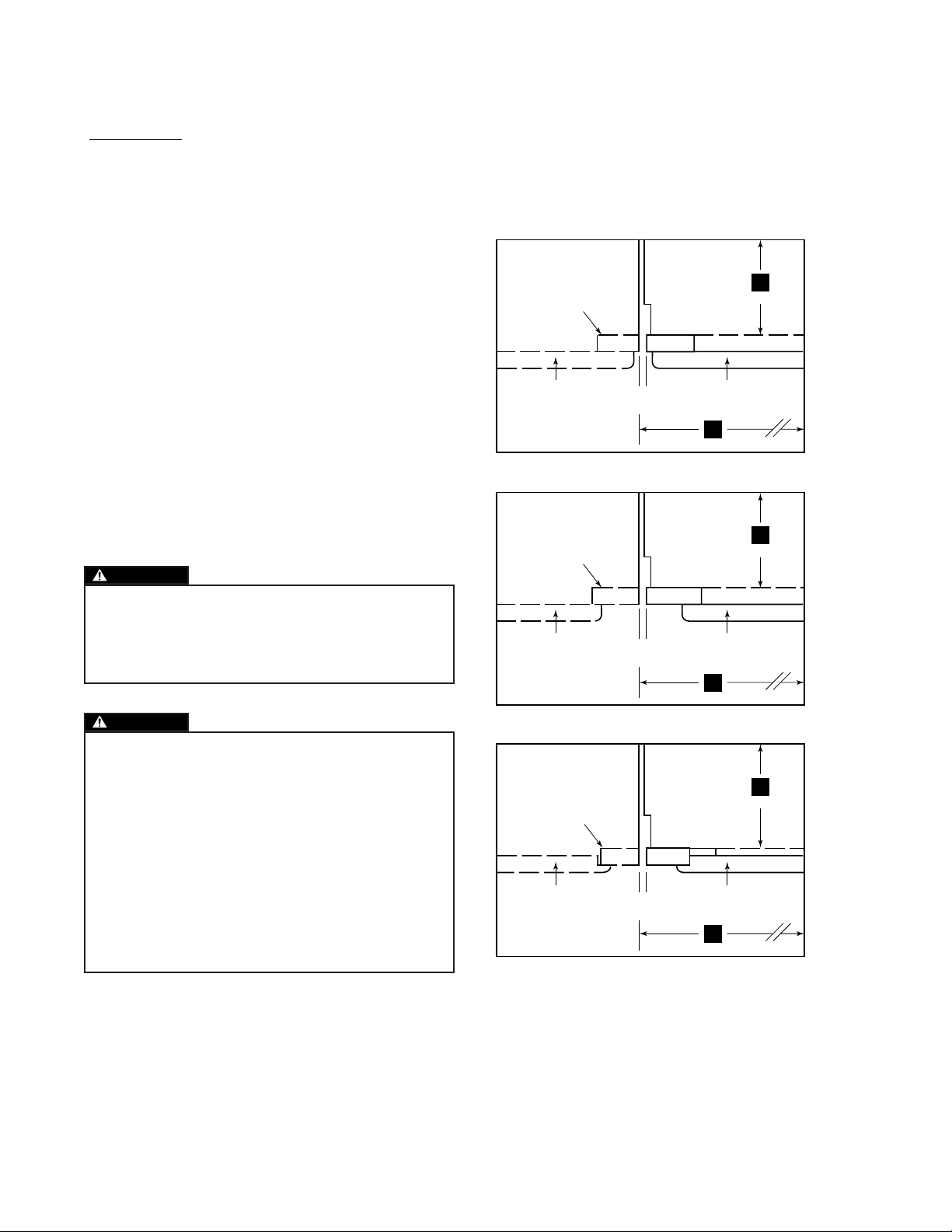
FRAMED CABINETRY – COMMON APPLICATIONS
(TOP VIEWS)
A-ALL REVEALS ARE 1/8 INCH (3MM)
27
(686)
TO WALL
24
(610)
27
(686)
TO WALL
24
(610)
27
(686)
TO WALL
24
(610)
TRADITIONAL FRAME – FULL OVERLAY
TRADITIONAL FRAME – STANDARD OVERLAY
TRADITIONAL FRAME – 3/8" OFFSET
CAUTION
As the reveal between cabinets and the 700 Series unit
decreases, the potential exists for severe finger pinch-
ing or crushing if a hand or fingers are placed in the
opening when the door is closing.
CAUTION
When 5/8-inch or larger panels are used and a reveal
less than 1/4-inch is maintained, the door panels may
cause damage to the Sub-Zero unit when the door is
open at the maximum 105˚ stop. You should use the
built-in 90˚ stop to prevent damage.
SPECIAL NOTE: In an installation where you are plac-
ing two 700 Series tall units next to one another and
providing a minimum 1/8-inch reveal, refer to illustra-
tion 8, you cannot assume the panel width is 265/8
inches as shown on the top.The panels will need to be
263/4inches to ensure a consistent reveal.
FRAMED CABINET APPLICATIONS
Illus. 7
700
SERIES
IMPORTANT NOTE: The height of a cabinet door can
exceed 451/4inches with little problem. However, you do
not want to go smaller than this height. See the following
pages.For the bottom drawer,the maximum panel height is
169/16 inches.It is critical to keep a minimum of a 4-inch toe
kick area free of panel to allow the unit to function effi-
ciently.
FRAMED CABINETRY
(BEADED INSET APPLICATION)
FRONT VIEW SIDE VIEW
27(686)
1
2
1(38) 1
2
1(38)
1
2
1
(38)
1
2
(38)
1
2
1
(38)
1413
16
3
4
47
(1213)
4(102)
24(610)
84
(2624)
1
2
*34
(876)
80**
(2032)
NOTE: SHADED AREA
INDICATES STATIONARY
STYLES AND RAILS.
A-ALL REVEALS ARE 1/4 INCH (6MM)
B-DRAWER RAILS ARE ATTACHED TO DRAWER FRONTS
C-BOTTOM RAIL MUST BE REMOVEABLE
CA
A
A
B
B
*4
(102)
TOP VIEW
A A
DOOR PANEL
CABINET DOOR TO WALL
SUB-ZERO
UNIT
27
(686)
24
(610)
*DIMENSIONS MAY VARY
**SEE PAGE 27 FOR DETAILED ILLUSTRATION
13 7
16
(342)
(376)
IMPORTANT NOTE: Refer to the full-scale illustrations at
the end of this section for specifics on panels and door
openings.
Illus. 6
INSTALLATION OF TALL UNIT
(DOOR CLOSED)
TOP VIEW – FULL SCALE
FRAMED CABINETRY
(105°MAXIMUM DOOR OPENING)
TOP VIEW-1/4 SCALE
1
8
3
4
MIN.
(3)
PANEL
SIDE MOLDING AND
INSTALLATION HARDWARE
PROVIDED BY SUB-ZERO
LINE OF INTERFERENCE
AT MAXIMUM DOOR OPENING
MOUNTING BRACKET SCREW
(19)
TO BACK
OF
TALL/BASE
UNIT
FLUSH
FURNITURE
FINISH
LINE OF INTERFERENCE
TO
WALL
24
(610)
24
(610)
SUB-ZERO DOOR
TO
WALL
24
(610)
LINE OF INTERFERENCE
SUB-ZERO
DOOR
PANEL WEIGHT LIMITS:
Door – 40 lbs.
Drawer – 12 lbs. each
257
8(657) APPLIANCE DOOR WIDTH
Illus. 13
DOOR PANEL HEIGHT
Door panels can grow beyond the 80-inch height to
accommodate any size of door as long as you stay
below the recommended door panel weight limit of
40 pounds.
Illustration 10 shows how the panel may grow and
what you need to consider doing to finish the area in
back of the door panel.
IMPORTANT NOTE: The valance you use to finish the
area behind the door panel must stay behind the front
plane of the finished molding as noted in illustration
10.
KICKPLATE CLEARANCE
Illustration 11 details the area below the lower draw-
er area where the operating mechanical equipment of
the Sub-Zero 700 Series unit is housed.
IMPORTANT NOTE:You must keep a minimum space
of four inches clear below the bottom edge of the
lower drawer panel, so the unit can be properly vent-
ed. In addition, any decorative base molding must be
removable for possible servicing and cleaning of the
condenser.
451
4
UPPER VALANCE DETAIL
(1150)
TO
BOTTOM
OF
DOOR
PANEL
TO
FLOOR
1
4
(6)
11
2(38)
TO WALL
VALANCE BY OTHERS
(CHECK CENTER SPREAD
OF THIS MANUAL FOR
CLEARANCE OF DOOR
PANEL EXCEEDING 80" HIGH)
ANY DECORATIVE VALANCE
CANNOT EXTEND BEYOND
THE FRONT OF THIS PLANE.
REMOVABLE MOLDING
BY SUB-ZERO
TOP HINGE
24
(610)
*FINISHED HEIGHT OF 80-INCHES IS TO TOP OF SUB-ZERO MOLDING
80*
(2032)
KICKPLATE DETAIL
10 9
16
(268)
16 9
16
(420)
PANEL
PANEL
10
(254)
A) 4
(102)
OPTIONAL
25
8
(67) 4
(102)
TO
911
16
(246)
1
2
(13)
FLOOR
TO WALL
24
(610)
BASE MOLDING MUST
BE REMOVABLE
B)
Illus. 10
Illus. 11
DUAL INSTALLATIONS
Optional components are necessary for the installa-
tion of two or more 700 Series units, where there is
two inches or less of space between the units.
Contact your Sub-Zero distributor for the proper com-
ponents and instructions. Note that panel sizes will
change, refer to illustration below.
265
8(676)
3
4(19) PANEL
APPLIANCE
DOOR WIDTH CABINETRY
OR SIDE
PANEL
CABINETRY
OR SIDE
PANEL
SUB-ZERO
UNIT
TO BACK
OF UNIT
257
8(657)
27
(686)
263
4(679)
3
4(19) PANEL 3
4(19) PANEL
DOOR
CABINETRY
OR SIDE
PANEL
CABINETRY
OR SIDE
PANEL
SUB-ZERO
UNIT
DOOR
SUB-ZERO
UNIT
263
4(679)
54(1372)
PANEL WIDTH DIMENSIONS
SINGLE UNIT
TWO UNITS SIDE BY SIDE
24
(610)
TO BACK
OF UNIT
24
(610)
25"
25" 25"
25"
1
8(3)
REVEAL
MIN.
*
1
8(3)
REVEAL
MIN.
*1
8(3)
REVEAL
MIN.
*
1
8(3)
REVEAL
MIN.
*
1
8(3)
REVEAL
MIN.
*
*SUBTRACT PANEL WIDTH FROM CABINETRY OPENING TO DETERMINE ACTUAL WIDTH OF REVEAL
Illus. 8