manuals.online logo
Brands
  1. Home
  2. •
  3. Brands
  4. •
  5. Sub-Zero
  6. •
  7. Refrigerator
  8. •
  9. Sub-Zero UC-24BG User manual

Sub-Zero UC-24BG User manual

Other manuals for UC-24BG

4

This manual suits for next models

5

Other Sub-Zero Refrigerator manuals

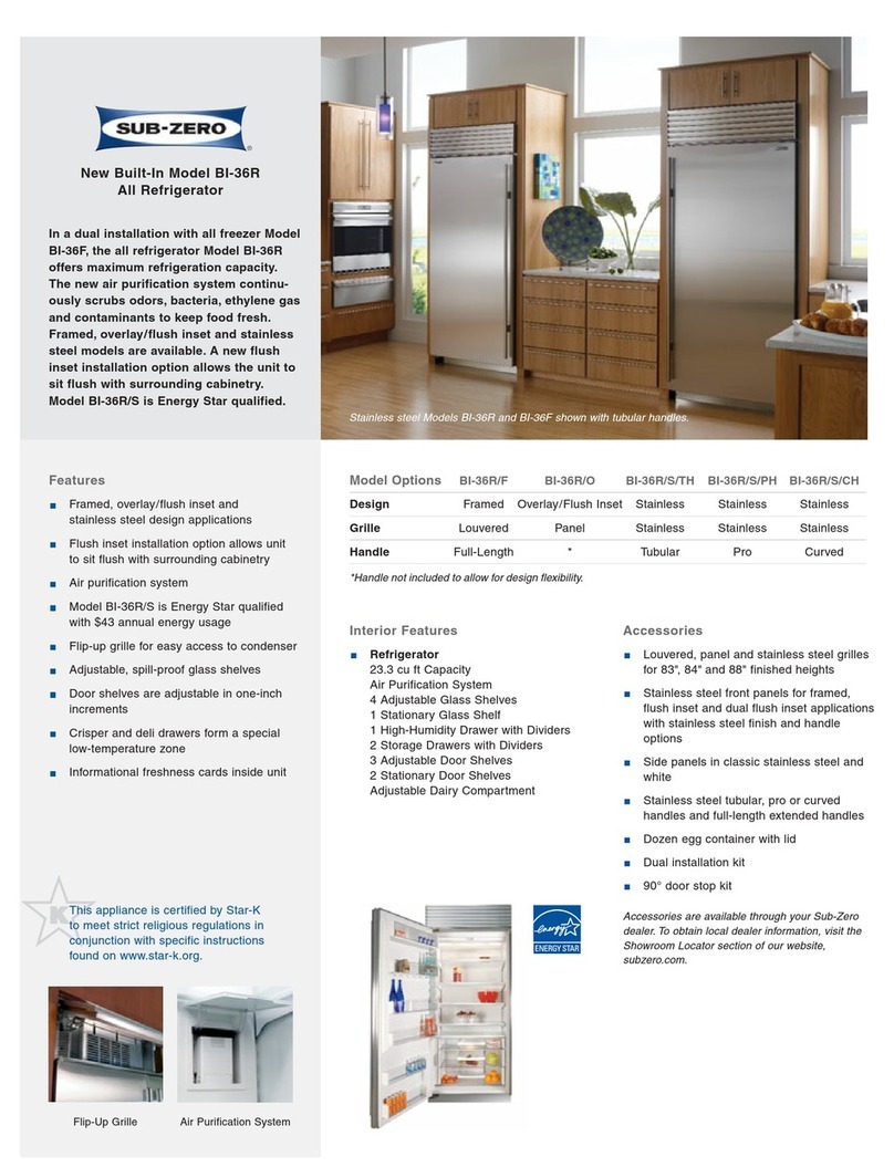
Sub-Zero BI36FSTHLH User manual

Sub-Zero

Sub-Zero BI36FSTHLH User manual

Sub-Zero IC-24R User manual

Sub-Zero

Sub-Zero IC-24R User manual

Sub-Zero IT36RRH User manual

Sub-Zero

Sub-Zero IT36RRH User manual

Sub-Zero I736TR User manual

Sub-Zero

Sub-Zero I736TR User manual

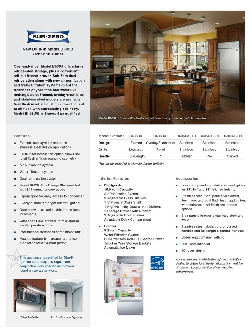
Sub-Zero BI-36R User manual

Sub-Zero

Sub-Zero BI-36R User manual

Sub-Zero BI-48SD User manual

Sub-Zero

Sub-Zero BI-48SD User manual

Sub-Zero ICBBI-36F User manual

Sub-Zero

Sub-Zero ICBBI-36F User manual

Sub-Zero 736TR User manual

Sub-Zero

Sub-Zero 736TR User manual

Sub-Zero 600 Series BI-36UG User manual

Sub-Zero

Sub-Zero 600 Series BI-36UG User manual

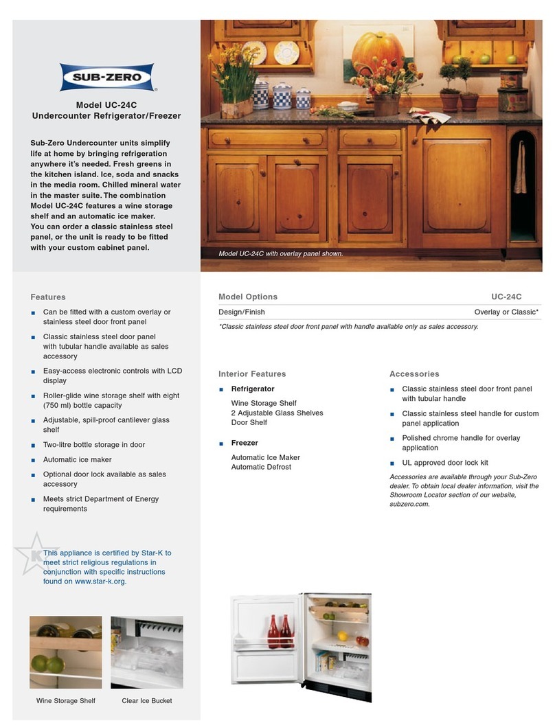
Sub-Zero UC-24C User manual

Sub-Zero

Sub-Zero UC-24C User manual

Sub-Zero UC-24B User manual

Sub-Zero

Sub-Zero UC-24B User manual

Sub-Zero PRO 48 User manual

Sub-Zero

Sub-Zero PRO 48 User manual

Sub-Zero Sub-Zero BI series User manual

Sub-Zero

Sub-Zero Sub-Zero BI series User manual

Sub-Zero PRO 48 User manual

Sub-Zero

Sub-Zero PRO 48 User manual

Sub-Zero 601R-2 Operating manual

Sub-Zero

Sub-Zero 601R-2 Operating manual

Sub-Zero Integrated Series User manual

Sub-Zero

Sub-Zero Integrated Series User manual

Sub-Zero ICB648PRO User manual

Sub-Zero

Sub-Zero ICB648PRO User manual

Sub-Zero BI-36R User manual

Sub-Zero

Sub-Zero BI-36R User manual

Sub-Zero 736TCI User manual

Sub-Zero

Sub-Zero 736TCI User manual

Sub-Zero 650G User manual

Sub-Zero

Sub-Zero 650G User manual

Sub-Zero 700 Series User manual

Sub-Zero

Sub-Zero 700 Series User manual

Sub-Zero PRO 48 User manual

Sub-Zero

Sub-Zero PRO 48 User manual

Sub-Zero 700BR User manual

Sub-Zero

Sub-Zero 700BR User manual

Sub-Zero ICBBI Series Service manual

Sub-Zero

Sub-Zero ICBBI Series Service manual

Popular Refrigerator manuals by other brands

Frigidaire FRS26TS7DW2 Use & care manual

Frigidaire

Frigidaire FRS26TS7DW2 Use & care manual

Fisher Scientific 10ECEEFSA manual

Fisher Scientific

Fisher Scientific 10ECEEFSA manual

Summit FF22BDRSS user manual

Summit

Summit FF22BDRSS user manual

Frigidaire FFRU17B2QWE use & care

Frigidaire

Frigidaire FFRU17B2QWE use & care

Hotpoint ENBGH 19xxx FW operating instructions

Hotpoint

Hotpoint ENBGH 19xxx FW operating instructions

Hitachi R-SG28KPH instruction manual

Hitachi

Hitachi R-SG28KPH instruction manual

Dometic RMH 7390 L operating instructions

Dometic

Dometic RMH 7390 L operating instructions

AEG S71700TSW0 user manual

AEG

AEG S71700TSW0 user manual

Electrolux ENB3669 Instruction book

Electrolux

Electrolux ENB3669 Instruction book

Electrolux ERN 2930 Instruction book

Electrolux

Electrolux ERN 2930 Instruction book

Beko GNE 60520 X user manual

Beko

Beko GNE 60520 X user manual

Jenn-Air JUR248LBES00 Use & care guide

Jenn-Air

Jenn-Air JUR248LBES00 Use & care guide

Dometic RGE 4000 Installation and operating manual

Dometic

Dometic RGE 4000 Installation and operating manual

Dometic L-0191B Brochure & specs

Dometic

Dometic L-0191B Brochure & specs

LG LRBP1031W - 10 Cu. Ft. Cabinet Depth Bottom Freezer... owner's guide

LG

LG LRBP1031W - 10 Cu. Ft. Cabinet Depth Bottom Freezer... owner's guide

Daewoo RN-33 Series user manual

Daewoo

Daewoo RN-33 Series user manual

Haier RF-8888-174 Service manual

Haier

Haier RF-8888-174 Service manual

Blaupunkt 5CK2 Series user manual

Blaupunkt

Blaupunkt 5CK2 Series user manual

manuals.online logo
manuals.online logoBrands
  • About & Mission
  • Contact us
  • Privacy Policy
  • Terms and Conditions

Copyright 2025 Manuals.Online. All Rights Reserved.

INSTALLATION GUIDE
Undercounter Refrigeration
Contents
Undercounter efrigeration ..................... 3
Undercounter Specifications .................... 4
Site Preparation .............................. 5
Undercounter Installation ...................... 7
Service Information .......................... 14
Features and specifications are subject to change at any time
without notice. Visit subzero.com/specs for the most up-to-
date information.
IMPO TANT NOTE: Throughout this guide, dimensions in
parentheses are millimeters unless otherwise specified.
Important Note
To ensure the safe and efficient installation of Sub-Zero
equipment, please take note of the following types of
highlighted information throughout this guide:
IMPO TANT NOTE highlights information that is especially
relevant to a problem-free installation.
CAUTION signals a situation where minor injury or product
damage may occur if instructions are not followed.
WA NING states a hazard that may cause serious injury or
death if precautions are not followed.
Undercounter Refrigeration 3
subzero.com/specs
Sub-Zero Undercounter Refrigeration
IMPO TANT NOTE: The importance of the installation of
the Sub-Zero undercounter unit cannot be overempha-
sized. Installation should be done by a qualified installer.
Before you begin the installation process, it is recom-
mended that you read this entire installation guide. There
are key details that you should take special care to
observe during the installation. By reading these instruc-
tions carefully, you will make the installation process
easier, problem-free and, most importantly, safe.
Any questions or problems regarding the installation
should be directed to your authorized Sub-Zero dealer or
Sub-Zero customer care at 800-222-7820. You may also
check the contact & support sectionofour website,
subzero.com.
Important product information, including the model and
serial number of your unit are listed on the product rating
plate, located inside the cabinet, in the upper left area of
the unit. Refer to the illustration.
Location of rating plate.
RATING PLATE
Undercounter Specifications 4
24" (610)
OPENING
DEPTH
24" (610)
OPENING WIDTH
24" (610)
OPENING DEPTH
341/2"(876)
OPENING
HEIGHT
TOP VIEW
FRONT VIEWSIDE VIEW
OPENING DIMENSIONS
237/8"(606) 24" (610)
34"
(864)
4" (102)
253/8"
(645)
13/4"(44)
Undercounter Models
OVE ALL DIMENSIONS
Specifications
INTE IO CAPACITY CU FT (L) F CU FT (L)
UC-24R, UC-24BG and UC-24RO 5.7 (161)
UC-24C(I) 3.6 (102) 1.1 (31)
SHIPPING WEIGHT LBS (KG)
All Models 130 (59)
Site Preparation 5
subzero.com/specs
Before You Start
Make sure the opening dimensions, door clearance,
electrical service and plumbing are correct for the model
you are about to install. Refer to specifications on the
following pages.
IMPO TANT NOTE: To operate properly, the door must
open a minimum of 90°. Use a minimum 3" (76) filler in
corner installations to assure a 90° door opening. Allow
enough clearance in front of the unit for full door swing.
TOOLS AND MATE IALS EQUI ED
•Appliance dolly able to support 130 lbs (59 kg)
•Level —2' (.6 m) and 4' (1.2 m) recommended
•Phillips and slotted screwdriver sets
•Wrench set and allen wrench set
•Crescent wrenches
•Various sized pliers
•5/16" hex bolt nut driver
•Drill and assorted drill bits
•Model UC-24CI—4' (1.2 m) of 1/4" copper, braided
stainless steel or PEX tubing and saddle valve for
water line (do not use self-piercing valves).
•Model UC-24CI—Tubing cutter.
•Masonite, plywood, 1/8" pressed fiberboard, cardboard
or other suitable material to protect finished flooring
Site Preparation 6
FRONT VIEW
151/2"
(394)
3" (76)
2" (51)
LEFT SIDE
OF OPENING
Location of electrical supply.
Plumbing Requirements
MODEL UC-24CI
For model UC-24CI, the water supply line for the ice
maker should be located within the shaded area shown in
the illustration below. Connect the water line from the ice
maker water valve to the house water supply line. Use an
easily accessible shut-off valve between the water supply
and the unit. Do not use self-piercing valves. A saddle
valve kit is available from your authorized Sub-Zero
dealer.
A line filter is required when water conditions have a high
sediment content. The ice maker operates on water
pressure of 20 psi (1.4 bar) to 100 psi (6.9 bar).
A reverse osmosis system can be used, provided there is
a consistent water pressure of 20 psi (1.4 bar) to 100 psi
(6.9 bar) supplied to the water valve at all times. A copper
line is not recommended for this application.
IMPO TANT NOTE: In some cases a reverse osmosis
water filter system may not be able to maintain the
minimum water pressure consistently.
FRONT VIEW
SHADED AREA
EXTENDS 1/2"(13)
FROM BACK WALL
151/2"
(394)
3" (76)
2" (51)
Location of water supply.
Electrical Requirements
The electrical supply should be located within the shaded
area shown in the illustration below. Follow the National
Electrical Code and local codes and ordinances when
installing the receptacle. A separate circuit, servicing only
this appliance is required.
IMPO TANT NOTE: The electrical outlet must be placed
so the grounding prong is to the right of the thinner
blades. The outlet must be flush with the back wall.
Model UC-24RO is designed and safe for use in outdoor
applications. When installed outdoors, a ground fault
circuit interrupter (GFCI) is required to reduce the risk of
electrical shock. A GFCI is not recommended for use with
other undercounter models and may cause interruption of
operation.
Electrical equirements
Power Supply 115 V AC, 60 Hz
Circuit Breaker 15 amp
Receptacle 3-prong grounding-type
Do not use an extension cord or two-prong adapter.
Electrical ground is required on this appliance.
Plumbing equirements
Water Supply Line 1/4" OD copper, braided stainless steel
or PEX tubing
Water Pressure 20–100 psi (1.4–6.9 bar)
Excess Water Line for Connection 26" (660) min
Unpack the Unit
Before moving the undercounter unit into position, make
sure all opening dimensions, electrical and plumbing
requirements are complete and accurate.
IMPO TANT NOTE: The floor under the undercounter unit
must be at the same level as the surrounding finished floor
to allow for removal of the unit for servicing.
Use an appliance dolly to move the undercounter unit near
the installation opening. Position the dolly at the side of
the unit to prevent damage to finished surfaces. Remove
and discard all packing materials and tape.
IMPO TANT NOTE: Do not discard the kickplate, anti-tip
bracket, hardware and the shipping bolts that hold the
wood to the bottom of the unit (leveling legs). These items
will be needed for the installation.
For models UC-24BG and UC-24C(I), the roller-assembly
wine shelves should be removed to reduce weight and
prevent them from rolling. To remove, pull the shelf out to
its full extension, gently and evenly lift up on both sides of
the front of the shelf and remove. Reverse the procedure
to reinstall the shelf.
Undercounter Installation 7
subzero.com/specs
Before moving the undercounter unit into position,
protect any finished flooring with appropriate materials
and secure the door closed.
Anti-Tip Bracket
An anti-tip bracket and hardware is provided with the
undercounter unit. Placement of the anti-tip bracket is
critical to a stable installation. The anti-tip bracket must be
installed securely.
The anti-tip bracket should be attached to the wall behind
the unit with the bracket flange located immediately above
the top of the unit. Refer to the illustration below.
For installations that cannot accommodate the anti-tip
bracket, the optional countertop bracket (provided) can
be used to secure the undercounter unit. This bracket will
secure the front of the unit to the underside of the coun-
tertop, above the unit. Refer to the illustration below. If it is
not possible to use the countertop bracket, wedge shims
along the sides and top of the unit to secure.
To prevent the unit from tipping forward and provide a
stable installation, the unit must be secured in place
with the anti-tip bracket.
1/4"(6)
ANTI-TIP
BRACKET
Anti-tip bracket. Countertop bracket.
COUNTERTOP
BRACKET
Undercounter Installation 8
Installation
IMPO TANT NOTE: If the undercounter unit has been laid
on its back or side, you must allow the unit to stand upright
for a minimum of 24 hours before connecting power.
With the undercounter unit near the installation opening,
plug the power cord into the electrical outlet. With power
applied to the unit, check for lighting and cooling. Once
you are satisfied that the unit is operating properly, shut
off power to the electrical outlet at the circuit breaker and
proceed.
LEVEL THE UNIT
Level the unit before sliding it into position. Leveling
cannot be completed with the unit pushed back in the
installation opening.
Using an adjustable wrench or pliers, turn each of the four
leveling legs clockwise to raise the unit and counterclock-
wise to lower the unit. For the location of the leveling legs,
refer to the illustration.
POSITION THE UNIT
Slide the undercounter unit back into position in the
installation opening. Make sure it contacts the anti-tip
bracket for a stable installation.
The undercounter unit provides the best access to its
contents when the front surface of the door panel extends
out from surrounding cabinets approximately 1/4"(6).
WATE LINE CONNECTION (MODEL UC-24CI)
For model UC-24CI, connect the plastic tubing from the
ice maker to the house water supply line with the fitting
connection kit, provided. Check all water line fittings for
leaks.
Purge the water line prior to final connection to the unit.
This will remove any debris that may be present in the
tubing from installing the new water line.
IMPO TANT NOTE: Let your customer know that the ice
maker will not produce ice immediately, and that the first
few batches of ice produced should be discarded. Allow
24 hours for proper ice production.
IMPO TANT NOTE: Water lines must not be exposed to
freezing temperatures. Exposure could cause damage to
the unit and home.
INSTALL KICKPLATE
Install the kickplate using the two #10 x 1/2" stainless steel
screws that are provided with the kickplate. Refer to the
illustration below.
The kickplate must be removed for servicing. The floor
cannot interfere with removal. Do not cover the louvered
section of the kickplate to allow proper air circulation.
Turn power back on to the electrical outlet.
To reduce the possibility of the unit tipping forward, the
front leveling legs must be in contact with the floor.
LEVELING LEGS
Location of leveling legs. Kickplate installation.
KICKPLATE
Door Panel
MODELS UC-24 AND UC-24C(I)
Models UC-24R and UC-24C(I) can be fitted with a
custom overlay or stainless steel door front panel. A stain-
less steel door panel with tubular or pro handle is available
as a sales accessory. Installation of the stainless steel
panel will be required.
For the overlay application, a decorative door panel and
handle hardware must be provided. Refer to the chart for
panel specifications.
You can match your handle hardware with surrounding
cabinetry or use a Sub-Zero accessory handle. Handles
must be attached directly to the overlay panel.
BEVE AGE CENTE MODEL UC-24BG
Stainless steel model UC-24BG/S is shipped from the
factory with the stainless steel door panel and tubular or
pro handle in place. No panel installation is required.
For overlay model UC-24BG/O, a decorative frame door
panel must be provided to surround the glass. The inside
edges of the panel that will be visible through the glass
must be finished. Refer to the chart for panel specifica-
tions.
You may also use your own handle hardware to match sur-
rounding cabinetry. If you do not use the pre-drilled holes
on the door of the unit, you will need to attach the handle
directly to the overlay panel.
IMPO TANT NOTE: For installations at or above 5,000'
(1524 m) in altitude, a special high altitude glass door unit
must be ordered.
OUTDOO MODEL UC-24 O
Model UC-24RO is shipped from the factory with the
stainless steel door panel and tubular or pro handle in
place. No panel installation is required.
IMPO TANT NOTE: Model UC-24RO must be built into
cabinetry and cannot be used in a freestanding applica-
tion.
Undercounter Installation 9
subzero.com/specs
A solid panel must not be installed over the glass door,
as this may cause moisture to form behind the panel.
Panel Specifications
OVE LAY PANEL WH
UC-24R, UC-24BG, UC-24C(I) 233/4"(603) 301/16"(764)
AILS AND STILES W
UC-24BG 21/4"(57) min
MAX PANEL WEIGHT
UC-24R and UC-24C(I) 20 lbs (9 kg)
UC-24BG 10 lbs (5 kg)
MIN PANEL THICKNESS
Overlay Panels 5/8"(16)
Undercounter Installation 10
Overlay Panel Installation
MODELS UC-24 AND UC-24C(I)
Inspect the overlay door panel for minimum thickness and
weight limit. Remove the two panel mounting brackets
attached to the front of the door and set aside.
Place the overlay panel lying face down on a protected
surface to ensure that the front is not scratched or
damaged. Position the plastic template (provided) flush
with the lower edge of the door panel. Be sure you are
following the exact location for the right-hand (RH) or left-
hand (LH) door swing. Refer to the illustration below for
placement of the mounting brackets.
Once you have located the proper placement for the
brackets, mark the pilot holes, remove the template and
drill pilot holes for mounting the brackets. It is best to start
with a few holes, position the bracket, drill the remaining
pilot holes and then secure the mounting bracket with the
#8 x 1/2" screws provided.
Exercise caution when drilling holes for mounting
hardware. This is especially critical with inset panels.
Before attaching the overlay panel to the door, insert two
screws, one in the center of each mounting position, just
far enough that the slotted holes on the hinge side door
panel bracket will slide under the heads. These positioning
screws will support the door panel during installation and
adjustment. Refer to the illustration below.
Install the door panel by engaging the tabbed bracket to
the handle side of the door first and then sliding the hinge
side mounting bracket onto the positioning screws on the
hinge side of the door. The panel can be adjusted 1/4"(6)
up and down and side to side.
Once the door panel is in place and adjusted correctly,
attach the four remaining #10 x 1/2" screws to the hinge
side mounting bracket and install the magnetic decorative
caps as shown in the illustration below.
DOOR
PANEL
BRACKET
CAP
SCREW
Panel installation.
301/16"
(764)
LH DOOR SWING
233/4"(603)
151/16"
(382)
31/2"
(89)
35/8"
(92)
215/8"(549)
RH DOOR SWING
7/8"
(22)
Overlay panel bracket location.