5
US
EN
JP
FR
DE
NL
ES
IT
PT
GR
NO
SE
FI
DK
RU
PL
CN
AR
3. PRE-OPERATION CHECKS
4. ELECTRIC STARTER MODELS
NOTE
Engine shipped from our factory is without oil.
Before starting engine, fill with oil. Do not over-fill.
1. CHECK ENGINE OIL (See Fig. )
Before checking or refilling engine oil, be sure the engine is
located on stable, level surface and stopped.
■Do not screw the oil gauge into the oil filler neck to check oil
level. If the oil level is low, refill to the upper level with the
following recommended oil.
■Use 4-stroke automotive detergent oil of API service class
SE or higher grade.
■Select the viscosity based on the air temperature at the
time of operation as shown in the table. (See Fig.-①)
Oil capacity (Upper level) : (L)
EX13/17/21 . . . . . . . . . . . . . . . . . . . . . 0.6
EX27/30 . . . . . . . . . . . . . . . . . . . . . . . . 1.0
EX35/40 . . . . . . . . . . . . . . . . . . . . . . . . 1.2
Explanation of Fig.-②
❶Oil Gauge
❷Upper Level
❸Lower Level
■For the engine with Oil Bath type air cleaner, fill the engine
oil upto the specified level of the oil bath (oil pan).
(See Fig.-③-❶)
Oil capacity in the Oil Bath (oil pan) :
EX13/17/21 . . . . . . . . . . . . . About 55 mL
2. CHECK FUEL (See Fig. )
WARNING
Do not refuel while smoking, near an open flame
or other such potential fire hazards. Otherwise
fire accident may occur.
■Stop the engine and open the cap.
■Use unleaded automotive gasoline only.
●Unleaded regular/premium or reformulated gasoline
containing no more than 10% Ethanol (E10), or 15%
MTBE may also be used.
●Never use gasoline containing ethanol exceeding 10%,
or MTBE exceeding 15% because engine or fuel system
damage could result.
●Never use stale or contaminated gasoline.
●Use of these non-recommended fuels may result in
reduced performance and/or denial of warranty.
Fuel tank capacity : (L)
EX13 . . . . . . . . 2.3 EX17 . . . . . . . .3.2
EX21 . . . . . . . . 3.2 EX27 . . . . . . . .5.6
EX35 . . . . . . . . 6.8 EX40 . . . . . . . .6.8
■Close the fuel valve before filling the fuel tank.
For electric starter operation, proper electric wiring
arrangements are needed before normal engine operation.
1. BATTERY
■Use a battery rated 12V-24AH or larger.
WARNING
■Charge the battery in a fully ventilated location.
■Batteries generate hydrogen gas, which can be
highly explosive. Do not smoke or allow flames
or sparks near a battery, especially during
charging.
■Be sure to confirm Battery polarity. Connect
positive (+) terminal first when mounting
battery, and disconnect negative (
-
) terminal
first when dismounting.
■Battery electrolyte contains sulphuric acid.
Protect your eyes, skin and clothing. In case
of contact, flush thoroughly with water and get
prompt medical attention, especially if your
eyes are affected.
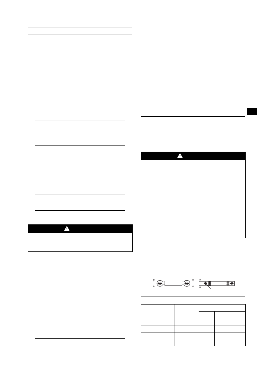
2. BATTERY CABLE
■Use a proper cable and ground wire to connect battery.
■For GROUND WIRE, use a flat braided wire of 20 sq. mm.
or larger sectional area.
LA406 LA406
CABLE
EARTH (GROUND) WIRE
25mm
6.5φ
7φ
6.5φ
Cable length Cable dia.
Wire gauge
AWG
(BS)
BWG
SAE JIS
Less than 1.5m 7.3 mm 1 6 AV15
1.5 m to 2.5 m 8.4 mm 0 4 AV20
2.5 m to 4 m 10.8 mm 3/0 2 AV30
Explanation of Fig.-①
❶Maximum Fuel level
■Do not fill above the top of the fuel filter screen (marked
❶), or the fuel may overflow when it heats up later and
expands.
■When filling the fuel tank, always use the fuel filter screen.
■Reattach the fuel cap by turning clockwise until reaching
the physical stop (about one quarter turn). Do not attempt
to turn past the physical stop or the fuel cap may be
damaged.
■Wipe off any spilled fuel before starting the engine.
EXseriesenEU7292.indd5EXseriesenEU7292.indd5 2011/11/2515:44:092011/11/2515:44:09