Subaru FORESTER2001 User manual

This service manual has been prepared
to provide SUBARU service personnel
with the necessary information and data
for the correct maintenance and repair of
SUBARU vehicles.
This manual includes the procedures for
maintenance, disassembling, reassem-
bling, inspection and adjustment of com-
ponents and diagnostics for guidance of
experienced mechanics.
Please peruse and utilize this manual
fully to ensure complete repair work for
satisfying our customers by keeping their
vehicle in optimum condition. When
replacement of parts during repair work is
needed, be sure to use SUBARU genu-
ine parts.
All information, illustration and specifica-
tions contained in this manual are based
on the latest product information avail-
able at the time of publication approval.
FUJI HEAVY INDUSTRIES LTD.
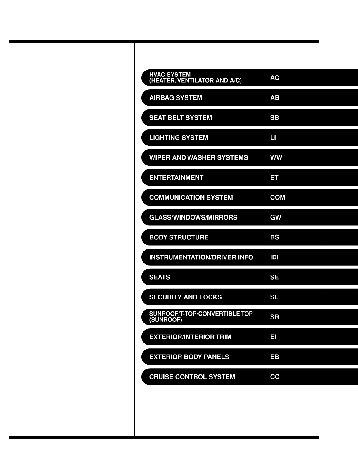
2001 FORESTER SERVICE MANUAL QUICK REFERENCE INDEX
BODY SECTION
G8050GE6

WIPER AND WASHER SYSTEMS WW
Page
1. General Description.....................................................................................2
2. Wiper and Washer System.........................................................................6
3. Combination Switch (Wiper)......................................................................10
4. Wiper Blade...............................................................................................12
5. Washer Tank and Motor............................................................................13
6. Front Wiper Arm........................................................................................14
7. Front Wiper Motor and Link......................................................................15
8. Front Washer.............................................................................................17
9. Rear Wiper Arm.........................................................................................19
10. Rear Wiper Motor......................................................................................20
11. Rear Washer .............................................................................................21
12. Wiper Control Relay..................................................................................23
13. Headlight Washer......................................................................................24

1. General Description S902001
A: SPECIFICATIONS S902001E49
Front wiper motor Input 12 V —54 W or less
Rear wiper motor Input 12 V —42 W or less
Front washer motor Pump type Centrifugal
Input 12 V —36 W or less
Rear washer motor Pump type Centrifugal
Input 12 V —36 W or less
B: COMPONENT S902001A05
1. FRONT WIPER S902001A0501
S6M0485A
(1) Wiper rubber
(2) Wiper blade ASSY
(3) Wiper arm
(4) Wiper link
(5) Wiper motor Tightening torque: N·m (kgf-m, ft-lb)
T1: 6.0 (0.61, 4.4)
T2: 20 (2.0, 14.5)
WW-2
GENERAL DESCRIPTION
Wiper and Washer Systems

2. REAR WIPER S902001A0502
S6M0486A
(1) Wiper blade ASSY
(2) Wiper arm
(3) Wiper motor
(4) Pivot cap
(5) Wiper arm cover Tightening torque: N·m (kgf-m, ft-lb)
T1: 5.9 (0.6, 4.3)
T2: 7.8 (0.8, 5.6)
WW-3
GENERAL DESCRIPTION Wiper and Washer Systems

3. WASHER TANK S902001A0503
S6M0564A
(1) Washer nozzle
(2) Washer hose
(3) Washer tank
(4) Washer tank cap
(5) Front washer motor
(6) Rear washer motor
(7) Grommet
(8) Headlight washer motor
(9) Motor bracket
(10) Headlight washer case
(11) Headlight washer upper nozzle
(12) Headlight washer lower nozzle
(13) Clip
(14) Joint valve
Tightening torque: N·m (kgf-m, ft-lb)
T: 6.0 (0.61, 4.4)
C: CAUTION S902001A03
쐌Reconnect connectors and hoses securely.
After reconnecting, confirm that each function operates normally.
쐌Be careful that wire harnesses of airbag system pass near electrical parts and switches.
쐌Wire harnesses and connectors of all airbag system are yellow color. Do not use a tester on these cir-
cuits.
쐌Care must be taken when installing the piping hose so that no bending, jamming, etc. are caused.
쐌If even a little oil or grease such as silicon oil gets in the tank and washer passages, an oil film easily
forms on the glass, causing the wiper to chatter and judder. Therefore, be careful not to let this happen.
WW-4
GENERAL DESCRIPTION
Wiper and Washer Systems

MEMO:
WW-5
GENERAL DESCRIPTION Wiper and Washer Systems

2. Wiper and Washer System S902394
A: SCHEMATIC S902394A21
1. WIPER AND WASHER (FRONT) S902394A2101
SG50-20
WW-6
WIPER AND WASHER SYSTEM
Wiper and Washer Systems

2. WIPER AND WASHER (REAR) S902394A2102
SG51-20
WW-7
WIPER AND WASHER SYSTEM Wiper and Washer Systems

3. HEADLIGHT WASHER S902394A2107
SG53-20
WW-8
WIPER AND WASHER SYSTEM
Wiper and Washer Systems

B: INSPECTION S902394A10
Symptom Repair order
Wiper and washers do not operate. (1) Wiper fuse (F/B No. 14, 15)
(2) Combination switch
(3) Wiper motor
(4) Wire harness
Wipers do not operate in LO or HI. (1) Combination switch
(2) Wiper motor
(3) Wire harness
Wipers do not operate in INT. (1) Combination switch
(2) Wiper motor
(3) Wire harness
Washer motor does not operate. (1) Washer switch
(2) Washer motor
(3) Wire harness
Wipers do not operate when washer switch is ON. (1) Washer motor
(2) Wire harness
Washer fluid spray does not operate. (1) Washer hose and nozzle
WW-9
WIPER AND WASHER SYSTEM Wiper and Washer Systems

3. Combination Switch (Wiper)
S902395
A: REMOVAL S902395A18
1) Loosen screw to remove a steering column
cover.
S6M0042
2) Disconnect connectors from combination
switches.
3) Loosen screw to remove combination switch.
B6M1499
B: INSTALLATION S902395A11
Install in the reverse order of removal.
C: INSPECTION S902395A10
쐌Inspect the continuity between each connector
terminal.
S6M0137
LHD model:
Switch position Test
connection Specified
condition
FRONT
OFF 7 —16 Continuity
INT 7 —16 Continuity
LO 7 —17 Continuity
HI 8 —17 Continuity
Washer ON 2 —11 Continuity
REAR
Washer ON 2 —10 —12 Continuity
OFF —No continuity
ON 2 —10 Continuity
Washer ON 2 —10 —12 Continuity
If continuity is not as specified, replace the switch.
RHD model:
Switch position Test
connection Specified
condition
FRONT
OFF 3 —12 Continuity
INT 3 —12 Continuity
LO 3 —11 Continuity
HI 2 —11 Continuity
Washer ON 8 —17 Continuity
REAR
Washer ON 8 —16 —18 Continuity
OFF —No continuity
ON 8 —18 Continuity
Washer ON 8 —16 —18 Continuity
If continuity is not as specified, replace the switch.
WW-10
COMBINATION SWITCH (WIPER)
Wiper and Washer Systems

쐌Intermittent operation inspection
1) Turn the wiper switch to INT.
2) Adjust the intermittent control switch to MAX.
3) Apply battery voltage to switch terminals 16 and 2, and inspect the voltage of terminals 7 and 2. (Mea-
sure the voltage from after the second time the wiper stops.)
B6M1465A
If operation is not as specified, replace the switch.
WW-11
COMBINATION SWITCH (WIPER) Wiper and Washer Systems

4. Wiper Blade S902392
A: REMOVAL S902392A18
While pushing locking clip (A) up, pull out blade
from arm to arrow direction.
B6M1570A
B: INSTALLATION S902392A11
1) Install in the reverse order of removal.
2) Confirm that clip was locked securely.
C: DISASSEMBLY S902392A06
Pull on side (A) of the wiper rubber stopper and
remove the rubber from the blade assembly.
B6M1496A
D: ASSEMBLY S902392A02
1) Insert the wiper rubber onto the blade so that
the stopper is in the position shown (at the bottom
of the wiper arm).
B6M1497
2) Make sure the wiper rubber is securely fas-
tened to the pull stopper (A).
B6M1498A
E: INSPECTION S902392A10
1) When the wiper does not perform well, inspect
the following:
쐌Make sure the movable part of the blade assem-
bly moves smoothly.
쐌Make sure the wiper rubber is not deformed or
damaged.
2) Replace with a new part if damage is found.
WW-12
WIPER BLADE
Wiper and Washer Systems

5. Washer Tank and Motor S902405
A: REMOVAL S902405A18
1) Disconnect the ground cable from the battery.
2) Remove the two bolts, and then disconnect the
connectors from washer motors.
B5M1464
3) Lift the washer tank, and then disconnect the
connector from headlight washer motor. Discon-
nect washer hoses.
S6M0561
4) Disconnect the washer hose from the motor,
and then detach the washer tank.
S6M0562
B: INSTALLATION S902405A11
Install in the reverse order of removal.
C: DISASSEMBLY S902405A06
Remove bolt, and then pull out washer motor from
tank.
S6M0563
D: ASSEMBLY S902405A02
1) Assemble in the reverse order of disassembly.
2) Confirm that water does not leak from installa-
tion area of motor.
E: INSPECTION S902405A10
Apply battery voltage to the connector terminal of
the washer motor and make sure the motor oper-
ates.
B6M1567
WW-13
WASHER TANK AND MOTOR Wiper and Washer Systems

6. Front Wiper Arm S902404
A: REMOVAL S902404A18
NOTE:
The positions for RHD model are symmetrically
opposite.
1) Open hood.
2) Remove cap.
3) Loosen nut to remove wiper arm.
S6M0050
B: INSTALLATION S902404A11
NOTE:
The positions for RHD model are symmetrically
opposite.
1) Install in the reverse order of removal.
2) Operate wiper once.
3) Align wiper blade to ceramic print point mark
(A) of front window pane.
S6M0049B
C: ADJUSTMENT S902404A01
NOTE:
The positions for RHD model are symmetrically
opposite.
Operate wiper once. Align wiper blade to ceramic
print point mark (A) of front window pane.
S6M0049B
WW-14
FRONT WIPER ARM
Wiper and Washer Systems

7. Front Wiper Motor and Link
S902406
A: REMOVAL S902406A18
NOTE:
The positions for RHD model are symmetrically
opposite.
1) Remove cowl panel. <Ref. to EI-25 REMOVAL,
Cowl Panel.>
2) Disconnect connector of motor, and remove
motor attaching bolts.
S6M0051
3) Remove cowl cover, and remove the motor link
nut on the back side of the motor.
S6M0052
4) Remove bolts which secure sleeve unit.
S6M0053
5) Remove wiper link from service hole in front
panel.
G6M0121
B: INSTALLATION S902406A11
Install in the reverse order of removal.
C: INSPECTION S902406A10
1) When battery is connected to terminal of
connectors, confirm that motor operates at low
speed.
S6M0055
2) When battery is connected to terminal of
connectors, confirm that motor operates at high
speed.
S6M0056
WW-15
FRONT WIPER MOTOR AND LINK Wiper and Washer Systems

3) Connect battery to terminals of connector, and
remove terminal connection with motor rotated at
low speed, and stop wiper motor through opera-
tion.
S6M0057
4) Connect battery and confirm that motor stops at
automatic stop position after motor operates at low
speed again.
S6M0058
WW-16
FRONT WIPER MOTOR AND LINK
Wiper and Washer Systems

8. Front Washer S902401
A: LOCATION S902401A13
S6M0559
B: REMOVAL S902401A18
1. NOZZLE S902401A1801
1) Remove the washer hose from the washer
nozzle.
2) Open the clips on the underside of the hood
with a thin screwdriver or other tool, and remove
the washer nozzle.
B6M1505
C: INSTALLATION S902401A11
1. NOZZLE S902401A1101
1) Install in the reverse order of removal.
2) Adjust the position of the washer liquid sprayer.
<Ref. to WW-18 ADJUSTMENT, Front Washer.>
D: INSPECTION S902401A10
쐌Make sure the nozzle and hose are not clogged.
쐌Make sure the hose is not bent.
WW-17
FRONT WASHER Wiper and Washer Systems

E: ADJUSTMENT S902401A01
NOTE:
Adjustment positions for left-handed vehicle. Carry
out left-right symmetry for adjustment positions for
right-handed vehicle.
1) Turn wiper switch to OFF position.
2) When vehicle stops, adjust washer injection
position as shown in the figure.
Injection position:
A: 410 mm (16.14 in)
B: 150 mm (5.91 in)
C: 370 mm (14.57 in)
D: 530 mm (20.87 in)
S6M0165A
WW-18
FRONT WASHER
Wiper and Washer Systems

9. Rear Wiper Arm S902402
A: REMOVAL S902402A18
1) Raise wiper arm cover.
2) Loosen nut to remove wiper arm.
S6M0061
B: INSTALLATION S902402A11
1) Install in the reverse order of removal.
2) Adjust the position of the wiper blade. <Ref. to
WW-19, ADJUSTMENT, Rear Wiper Arm.>
C: ADJUSTMENT S902402A01
1) Operate rear wiper once.
2) Adjust wiper blade to original position as shown
in figure.
Original position:
A: 30±5 mm (1.18±0.20 in)
S6M0059A
WW-19
REAR WIPER ARM Wiper and Washer Systems
Other manuals for FORESTER2001
2
Table of contents
Other Subaru Toy manuals
Popular Toy manuals by other brands

Carrera RC
Carrera RC Turnator - Super Flex Assembly and operating instructions

Horizon Hobby
Horizon Hobby Mystique RES 2.9m ARF instruction manual

Chicco
Chicco Turbo Touch instruction manual

Airigami
Airigami Papier Avion AirBus A320-Neo quick guide

KIDS BIGBEN
KIDS BIGBEN MICVF operating instructions

marklin
marklin 39235 user manual