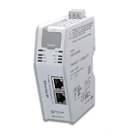
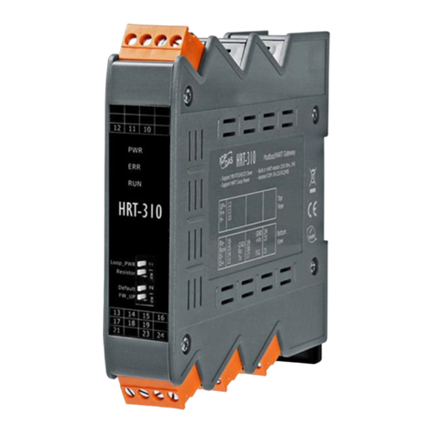
Submeter Solution NoWire 2100 User manual

NoWire Model 2100 Installation and Operation Manual
NoWire Model 2100 Submeter Solutions, Inc., 888-64METER Page 1
NoWire Model 2100 – Wireless Gateway
(wireless digital points for meters and industrial equipment)
ubmeter olutions, Inc.
Note:
The following manual is for the
previous
version
NoWire 1100. The operation for NoWire 2100 is
generally the same. ee section 11 for specifics about
NoWire 2100.

NoWire Model 2100 Installation and Operation Manual
NoWire Model 2100 Submeter Solutions, Inc., 888-64METER Page 2
Installation and Operation Manual
Table of Contents:
1 Overview ............................................................................................................................................... 4
2 Warnings ............................................................................................................................................... 4
3 NoWire Quick tart ............................................................................................................................... 4
3.1 Configuring a Wireless Input Pulse Meter .................................................................................... 4
3.2 Configuring a Wired Input Pulse Meter ........................................................................................ 6
4 NoWire Circuit Board ............................................................................................................................ 8
5 Installation Checklist ............................................................................................................................. 9
5.1 Required items included ............................................................................................................... 9
5.2 Items sold separately .................................................................................................................... 9
5.3 Hardware you must provide ......................................................................................................... 9
6 Installation Instructions ........................................................................................................................ 9
6.1 Mount the NoWire enclosure ....................................................................................................... 9
6.2 Attach optional external wiring to NoWire................................................................................. 10
6.2.1 Wired Pulse Inputs .............................................................................................................. 10
6.2.2 Wired Pulse Outputs ........................................................................................................... 10
6.2.3 R 232/R 485 Connections .................................................................................................. 10
6.2.4 Apply Power to NoWire ...................................................................................................... 10
7 etup Menus Operation ...................................................................................................................... 11
7.1 Meter data display and setup menus ......................................................................................... 11
7.2 ystem Items menu ..................................................................................................................... 12
7.3 Wireless Input menu ................................................................................................................... 13
7.4 Wired Pulse Input menu ............................................................................................................. 14
7.5 Pulse Output menu ..................................................................................................................... 15
8 Detail of Operations ............................................................................................................................ 15
8.1 NoWire Operation ....................................................................................................................... 15
8.1.1 Input Point Display creens................................................................................................. 15
8.1.2 ystem tatus creen .......................................................................................................... 16
8.1.3 tatus LED codes ................................................................................................................. 16
8.1.4 Wired Pulse Input and Pulse Output green LEDs ................................................................ 17
8.2 Wireless ystem .......................................................................................................................... 17
8.2.1 Wireless hardware .............................................................................................................. 17

NoWire Model 2100 Installation and Operation Manual
NoWire Model 2100 Submeter Solutions, Inc., 888-64METER Page 3
8.2.2 How the wireless communication works ............................................................................ 17
8.2.3 Basics of Radio Frequency (RF) ........................................................................................... 17
8.2.4 Wireless ystem Planning ................................................................................................... 20
8.3 The Installation Process .............................................................................................................. 21
8.3.1 Project Coordination ........................................................................................................... 21
8.3.2 Install NoWire ..................................................................................................................... 21
8.3.3 Assign the wireless transmitters ......................................................................................... 21
8.3.4 Install the transmitters ........................................................................................................ 21
9 NoWire pecifications ......................................................................................................................... 25
9.1 General pecifications ................................................................................................................. 25
9.2 Wireless pecifications ............................................................................................................... 25
10 Copyright Information .................................................................................................................... 26
11 NoWire 2100 pecifics .................................................................................................................... 27
11.1 Features different from NoWire 1100 ........................................................................................ 27
11.1.1 Ethernet and Wifi ................................................................................................................ 27
11.1.2 Multiple LEDs for easy troubleshooting .............................................................................. 27
11.1.3 Option to how/Hide meters from display ......................................................................... 28
11.1.4 Meter non-advancing alert ................................................................................................. 28
11.1.5 Barrel type plug in power supply ........................................................................................ 28
11.1.6 Modbus supports both 9600 and 19.2k baud ..................................................................... 28
11.1.7 Removed Pulse Outputs ...................................................................................................... 28
11.1.8 Cell upport via External Gateway ...................................................................................... 28

NoWire Model 2100 Installation and Operation Manual
NoWire Model 2100 Submeter Solutions, Inc., 888-64METER Page 4
1Overview
The NoWire Model 1100 provides a wireless link for digital input/output signals.
1. Display readings wirelessly from up to 32 water, gas, and electric meters or run-time sensors via
a wireless connection to your meter’s digital pulse output.
2. Display readings from up to 4 direct wired water, gas, and electric meters or run-time sensors
via NoWire’s 4 wired pulse inputs.
3. Provide a wireless link for 4 digital output signals to digital input equipment. Any of the 32
wireless or 4 wired input points can be routed to NoWire’s 4 optically isolated outputs. This
creates a wireless link for industrial control signals or creating an additional pulse output for
meters.
4. No software is required. All configuration is done through setup menus using the three
pushbuttons and LCD display.
5. Data from NoWire can be pushed to the internet via CellConnect™ G M Cell modem,
WebConnect™ Ethernet modem, or a third party device via Modbus RTU communications.
2Warnings
WARNING: A potential risk exists if this Operations and Installation Manual are not followed.
3NoWire Quick Start
This Quick tart section is to help you get up to speed with how to setup and configure the basics of
NoWire quickly. It is not intended to replace other instructions and details elsewhere in this manual but
to simply allow you to get familiar with the operation of this product.
3.1 Configuring a Wireless Input Pulse Meter
1. You will need the NoWire 1100, a 12VDC power supply, an
EN1501 wireless pulse transmitter, and a small screw driver.
2. Remove the NoWire cover and connect the 12VDC power
supply positive and negative wires to the V+ and V- terminals of
the terminal block in the bottom left corner of the circuit
board.
3. Plug the 12VDC power supply into a 120V outlet and wait for
NoWire to power up and go through its self checks.
4. Follow the steps below. The text between the LCD screen
images is the NoWire button to press to move to the next
screen.
CHAN E
NEXT
The setup menus are password protected. The factory default password is 00000 and
may be changed in the ystem Items sub-menu. Pressing NEXT will get you into the
setup menus.
12VDC power supply connection.

NoWire Model 2100 Installation and Operation Manual
NoWire Model 2100 Submeter Solutions, Inc., 888-64METER Page 5
CHAN E
CHAN E
NEXT
CHAN E
BACK
Pressing NEXT will rotate through the various menus. It rotates through the ystem Items, the 32 Wireless Inputs, the 4
Wired Pulse Inputs, and the 4 Wired Pulse Outputs. Press NEXT once to get to Wireless Input #1. Once there, press
CHANGE to setup Wireless Input #1.
The first sub-menu item allows you to tell NoWire to display Wireless Input #1 on the display. Press CHANGE
repeatedly to toggle between Yes and No. Once Yes is selected, press BACK to save the selection.
Pressing the NEXT key will rotate through Wireless Input #1’s sub-menu items. Press NEXT once to modify the
Description. Press CHANGE to begin Description changes.
CHAN E &
NEXT
The CHANGE and NEXT buttons are used to modify the characters of a text
or numeric entry field. CHANGE increments the character. NEXT moves to
the next character position. Press and hold a button for rapid entry. Use
the CHANGE and NEXT buttons to enter “WI 1” for the description. When
done press BACK.
BACK
Press the NEXT button to rotate
through the various settings until you
get to the Assign Xmitr setting, then
press CHANGE to have NoWire wait
for the EN1501 reset signal.
NEXT,
NEXT…
CHAN E
NEXT
CHAN E
Tip:
Press and hold the
CHANGE
button to rapidly move through characters to select.
Tip: Press and hold the BACK button and, while still holding it, press the CHANGE button. This moves
backwards one character. This is helpful if you rapidly scroll past the character you intended.

NoWire Model 2100 Installation and Operation Manual
NoWire Model 2100 Submeter Solutions, Inc., 888-64METER Page 6
5. Open the case of the EN1501 pulse transmitter by pressing in on the right side that has the small
hole. Press the reset button to assign the transmitter. Close the transmitter case.
Press the BACK button 2 times to exit the setup menus. The display now alternates between the two
following screens:
3.2 Configuring a Wired Input Pulse Meter
1. You will need the NoWire 1100, a 12VDC power supply, and a
small screw driver.
2. Remove the NoWire cover and connect the 12VDC power
supply positive and negative wires to the V+ and V- terminals of
the terminal block in the bottom left corner of the circuit
board.
3. Plug the 12VDC power supply into a 120V outlet and wait for
NoWire to power up and go through its self checks.
4. Follow the steps below. The text between the LCD screen images is the NoWire button to press
to move to the next screen.
Reset
Button
This screen indicates when the transmitter reset signal was received.
You may press NEXT multiple times to see other information about the transmitter.
The second screen displays the meter reading of Wireless Input #1. If you had a meter connected to the terminal block
of the EN1501 pulse transmitter you would see the meter reading as pulses are received by the connected meter.
CHAN E
NEXT
The setup menus are password protected. The factory default password is 00000 and
may be changed in the ystem Items sub-menu. Pressing NEXT will get you into the
setup menus.
12VDC power supply connection.

NoWire Model 2100 Installation and Operation Manual
NoWire Model 2100 Submeter Solutions, Inc., 888-64METER Page 7
5. Press the BACK button 2 times to exit the setup menus. The display now alternates between the
two following screens:
6. To simulate a meter pulse you may short the P1 and PG terminals. Each time these terminals
are connected together a pulse is recognized by NoWire and the meter reading will increment.
NEXT,
NEXT…
CHAN E
Pressing NEXT will rotate through the various menus. It rotates through the ystem Items, the 32 Wireless Inputs, the 4
Wired Pulse Inputs, and the 4 Wired Pulse Outputs. Press NEXT 31 times will land you on the Pulse Input #1 setup menu
item. Once there press CHANGE to setup Wired Pulse Input #1.
Pressing the NEXT key will rotate through Wired Pulse Input #1’s sub-menu items. Press NEXT once to modify the
Description. Press CHANGE to begin Description changes.
CHAN E &
NEXT
The CHANGE and NEXT buttons are used to modify the characters of a text
or numeric entry field. CHANGE increments the character. NEXT moves to
the next character position. Press and hold a button for rapid entry. Use
the CHANGE and NEXT buttons to enter “PI 1” for the description. When
done press BACK.
BACK
CHAN E
CHAN E
BACK
The first sub-menu item allows you to tell NoWire to display Wired Pulse Input #1 on the display. Press CHANGE
repeatedly to toggle between Yes and No. Once Yes is selected press BACK to save the selection.
NEXT
CHAN E
The second screen displays the meter reading of Wired Pulse Input #1. If you have a meter connected to the terminal
block connection P1 and PG you would see the meter reading as pulses are received by the connected meter.
Touch P1 and PG together to
simulate a wired meter pulse.
PG P1
Tip:
Press and hold the
CHANGE
button to rapidly move through characters to select.
Tip: Press and hold the BACK button and, while still holding it, press the CHANGE button. This moves
backwards one character. This is helpful if you rapidly scroll past the character you intended.

NoWire Model 2100 Installation and Operation Manual
NoWire Model 2100 Submeter Solutions, Inc., 888-64METER Page 8
4NoWire Circuit Board
1. 12VDC External power connection, V+ : 12VDC, V- : Ground.
2. 4 Wired Pulse Input connections. P1 & P2 are the positive terminal and share PG as the negative
(ground) terminal. P3 & P4 are the positive terminal and share PG as the negative (ground)
terminal.
3. Optically Isolated Pulse Outputs. 1+ is the positive terminal and 1- is the negative terminal.
ame for points 2, 3, and 4. May not be optically isolated if Pulse Output Jumpers (see 10) are
set as such.
4. R 485 Half Duplex Modbus connection.
5. COM2, 9 pin female D connector.
R 485: Pin 1: D+, Pin 9: D-, Pin 5: Gnd.
R 232: Pin 2: TX, Pin 3: RX, Pin 5: Gnd.
6. 120 ohm R 485 termination resistor jumper (J18). Top=No Connected, Bottom=Connected
7. Main tatus LED. olid green: No issues exist, Blinking Red, issues exist. ee section [link] for
more information on blink codes.
8. Wired Pulse Input tatus LEDs. Green LED On: input closed, Off: Input open.
9. Pulse Output tatus LEDs. Green LED On: output closed, Off: output open. Red LED blinking:
issues exist with Wireless Input that is assigned to the output.

NoWire Model 2100 Installation and Operation Manual
NoWire Model 2100 Submeter Solutions, Inc., 888-64METER Page 9
10. Pulse Output jumpers. Allows for output connections to power and ground for making powered
outputs (voiding optical isolation). Output point jumpers to the right: Pulse Output is optically
isolated and non-powered. Output point jumpers to the left: Pulse Output is connected to
NoWire power and ground for creating a non-isolated 5V powered output.
11. LCD contrast adjustment (VR1).
12. FW update jumpers J1 and J5.
13. COM1, 9 pin female D connector for FW update.
14. LCD menu navigation push buttons. Press and hold for repeat key operation.
15. Connector for external EN4000 wireless receiver. Only utilized with NoWire 1100-2 models
without the internal wireless EN4000 receiver.
16. 1 and 2 Red status LEDs. pecial status indication. 1 blinking: EN4000 wireless receiver
communications, 2 blinking: COM2 communications.
5Installation Checklist
NoWire installation requires the following items:
5.1 Required items included
•NoWire 1100 with internal receiver.
•Power supply: 12VDC, 500mA Class II.
•mall flat head screw driver for NoWire terminal blocks and transmitter terminal block
connections.
5.2 Items sold separately
•EN1501 pulse transmitters or EN1210 universal transmitters for wireless points.
•Outdoor enclosures to house the transmitters.
•Meters with digital pulsers.
5.3 Hardware you must provide
•Low voltage wiring (telephone, cat5 or thermostat wire) for connection from your meters to the
transmitters, from the meters to the wired pulse inputs of NoWire, and from the pulse outputs
to your input equipment.
•R 485/R 232 compatible cabling for connection to Com2 Modbus serial port or terminal block
connection.
•Mounting screws for attaching NoWire enclosure to a flat surface.
•½” conduit and conduit fittings connecting into NoWire.
•Any additional tools required for the installation.
6Installation Instructions
6.1 Mount the NoWire enclosure
•Here are some items to consider when deciding where to permanently locate the NoWire
enclosure.
oPlace where it will be easy to view the NoWire LCD display.
oNoWire is outdoor rated if proper watertight conduit connections are used.
oLocate out of direct sunlight to avoid exceeding the maximum temperature rating.

NoWire Model 2100 Installation and Operation Manual
NoWire Model 2100 Submeter Solutions, Inc., 888-64METER Page 10
oLocate near a 120V outlet where the NoWire power supply will be plugged in.
oAllow room for conduit bends and runs that connect to the bottom of the NoWire
enclosure. (if required for application)
oLocate away from other equipment per your local electrical codes.
oLocate in an area that allows for optimal wireless communications from the meter
transmitters. Though the wireless communications was designed for use inside of
buildings with obstacles and such it is best to avoid mounting NoWire in enclosed rooms
that have metal or thick rebar reinforced concrete walls or deep down in sub-basements
far away from the transmitters that need to be seen by it. If this is unavoidable then
you may need an external receiver (NoWire 1100-2) that can be mounted in an optimal
location connected to NoWire up to 50 feet away. Repeaters may also be used in this
situation. ee the Wireless Theory of Operation section.
•Remove the NoWire cover by unscrewing the 4 corner screws on the cover.
•Note the deep channels in the corners of the enclosure that have a 1/8” hole at the bottom.
This is where mounting screws are inserted. These do not need to be water tight since they are
outside the front cover gasket.
•Using the appropriate mounting screws for your location, attach the NoWire enclosure to your
flat surface.
•If you wish to use conduit for routing your NoWire wiring, you may remove the wire fitting on
the bottom of the NoWire enclosure and attach a ½” conduit. Use a water tight fitting if you
need to keep NoWire water tight.
6.2 Attach optional external wiring to NoWire
6.2.1 Wired Pulse Inputs
If you are using wired pulse inputs to directly connect your meters then wire the pulse output wires
from the meters into terminals P1 through P4 utilizing the PG terminals as the common ground
reference point. ee [link] for more details on wired pulse inputs.
6.2.2 Wired Pulse Outputs
If you are using the pulse outputs to connect to external equipment do the following: For pulse output
#1 wire the 1+ terminal to the positive signal of your equipment and the 1- terminal to the negative or
ground reference signal of your equipment. For pulse output 2 through 4 wire to terminals 2+/ 2-, 3+/
3-, and 4+/ 4- respectively.
6.2.3 R 232/R 485 Connections
If you are communicating with NoWire using Modbus connect using R 232 or half duplex multi-drop
R 485. For R 232 connections connect your R 232 cable to NoWire COM2 DB9 female connector. For
R 485 either connect to D+, D-, and GND on the NoWire terminal block or connect to pin 1 (D+), pin 9
(D-) and pin 5 (GND) to NoWire COM2 DB9 female connector.
6.2.4 Apply Power to NoWire
NoWire comes with a 12VDC power supply. Before plugging the power supply into a 120V outlet, route
the power supply wire up thru the NoWire wire entry location on the bottom of the enclosure and
connect the wires to the V+ and V- terminal block on the bottom left side of the NoWire circuit board.
Be sure the positive wire is connected to V+ and the negative wire is connected to V-. The + and –
designations should be shown on the power supply itself or the power supply wires. Once your power

NoWire Model 2100 Installation and Operation Manual
NoWire Model 2100 Submeter Solutions, Inc., 888-64METER Page 11
connections are complete to NoWire and you have double checked all your other wiring connections to
NoWire, plug in the 12VDC power supply to the 120V outlet.
7Setup Menus Operation
7.1 Meter data display and setup menus
CHAN E
NEXT
(if valid)
User changeable passcode is
entered here. Default is 00000.
CHAN E increments each digit.
NEXT moves to the next digit. If the
displayed passcode is correct then
flow will move to the ystem Items
in the setup menu.
BACK
Repeatedly pressing NEXT will rotate
from this option to the 32 Wireless
Inputs, the 4 Wired Pulse Inputs, and
the 4 Pulse Outputs.
CHAN E will go into the setup menu
for the item displayed. ee details on
the individual setup menus below.
BACK will exit the setup menu.
Every 5 secs,
NEXT
Every 5 secs,
NEXT
Continues through all
displayed input points
The top “NoWire 1100” screen displays
input points status on the second line.
On each displayed wireless point the top
right most character is reserved to display
wireless point status. In this case the “T”
indicating “Tamper” signifying the
transmitter case is open.
NEXT
NEXT
all 32 Wireless Inputs
NEXT
all 4 Wired Pulse Inputs
NEXT
all 4 Pulse Outputs
Up to top
CHAN E to view
CHAN E to view
CHAN E to view

NoWire Model 2100 Installation and Operation Manual
NoWire Model 2100 Submeter Solutions, Inc., 888-64METER Page 12
7.2 System Items menu
NEXT
Up to top
CHAN E to edit
CHAN E to edit
CHAN E to edit
NEXT
NEXT
NEXT
CHAN E to edit
NEXT
CHAN E to edit
NEXT
CHAN E to edit
Change the current time.
Change the current date.
Change whether the date is displayed in 12 hour format (5:43pm) or 24
hour format (17:43).
Turn the LCD backlight on or off.
If you are using NoWire without an EN4000 wireless receiver turn this
option off. This is if you are using NoWire for Wired Pulse Inputs only.
This allows you change the passcode for entering the setup menus. Be sure
to write down the changed passcode prior to exiting the setup menus. You
will now use the changed passcode when entering the setup menus.
NoWire Firmware Version.
NEXT
NEXT
CHAN E to edit
Options are Modbus, G M Cell, and Ethernet/Wifi. Change to G M Cell if
using CellConnect™ Cellular Modem. Change to Ethernet/Wifi if using
WebConnect™ Ethernet or Wifi Modem. ee installation manual for
specific option selected.
NEXT,
NEXT…
CHAN E to edit
Various status and configuration menu items depending on Com2 option
selected in previous menu item. ee installation manual for specific
option selected.

NoWire Model 2100 Installation and Operation Manual
NoWire Model 2100 Submeter Solutions, Inc., 888-64METER Page 13
7.3 Wireless Input menu
NEXT
CHAN E to edit
CHAN E to edit
CHAN E to edit
NEXT
NEXT
NEXT
CHAN E to edit
NEXT
CHAN E to edit
NEXT
CHAN E to edit
Change the wireless input point description that is displayed in the
rotating meter reading screens.
Change the wireless input point current meter reading. This is usually done to
match the actual meter reading with the reading that is displayed on NoWire.
Change the wireless input point pulse value. This is the value that is added to the
meter reading for each pulse that is received by NoWire. Valid range is 0.0001 to
9999.999. A value of 1.0000 will increment the meter reading by 1 each time a
pulse signal is received by the meter attached to this wireless point transmitter.
Change the number of decimal places that are displayed when displaying the
meter reading. Valid range is 0 to 3.
Change to yes if you wish this wireless input point to be displayed in the
rotating meter reading screens once you exit the setup menus.
Change the wireless input point units that is displayed in the rotating
meter reading screens after the meter reading.
NEXT
CHAN E to edit
Change if a pulse output will follow this wireless input. If a pulse output is already
assigned by another input then it will not be available for selection. This is handy
if you to drive external equipment with the wirelss input pulses.
NEXT
(if transmitter assigned)
CHAN E to edit
This allows you to assign a transmitter to this wireless input. After pressing
CHANGE the display will indicate to press the reset button on the transmitter and
will wait for you to do so. Open up the transmitter case and find the reset button
to press. If the transmitter is already assigned this display allows you to remove
the transmitter associated with this wireless input point.
NEXT
Displays the date and time when NoWire received the last transmission
from the assigned transmitter. tatus display only.
NEXT
CHAN E to edit
Change to YE if you wish to perform leak alarm detection on this point. A leak
alarm will be detected if the value for this input changes every consecutive 2.5
hour period for 48 hours. A leak alarm will clear if the value for this input does
not change for two consecutive 2.5 hour periods. An “L” is displayed for the input
point if a leak alarm has been detected.
Tip:
Press and hold the
CHANGE
button to rapidly move through characters to select.
Tip: Press and hold the BACK button and, while still holding it, press the CHANGE button. This
moves backwards one character. This is helpful if you rapidly scroll past the character you intended.

NoWire Model 2100 Installation and Operation Manual
NoWire Model 2100 Submeter Solutions, Inc., 888-64METER Page 14
7.4 Wired ulse Input menu
NEXT
Displays the ID of the transmitter assigned to this wireless input. tatus
display only.
NEXT
Displays the type of transmitter assigned to this wireless input. tatus display only.
NEXT
Displays the number of internal pulses seen by the transmitter. For EN1501
transmitters these counts come from the transmitter message and are cleared when the
reset button of the transmitter is pressed. For EN1210 and other transmitters NoWire
increments this count each time the Alarm0 bit status is cleared. tatus display only.
NEXT
Displays the transmitter status. T=tamper: case open. R=transmitter reset. F=fast mode
(transmission once per minute). B=battery low. L=leak alarm. Z=transmitter not heard
from for more than 24 hours. OK indicates there are no issues with this transmitter.
tatus display only.
Displays the signal strength of the last reception from the transmitter. Levels are on a
Db scale. A level of 4 or more is a good signal.
Up to top
NEXT
CHAN E to edit
CHAN E to edit
CHAN E to edit
NEXT
NEXT
NEXT
CHAN E to edit
NEXT
CHAN E to edit
Change the wired pulse input point description that is displayed in the
rotating meter reading screens.
Change the wired pulse input point current meter reading. This is usually done to
match the actual meter reading with the reading that is displayed on NoWire.
Change the wired pulse input point pulse value. This is the value that is added to the
meter reading for each pulse that is received by NoWire. Valid range is 0.0001 to
9999.999. A value of 1.0000 will increment the meter reading by 1 each time a pulse
signal is received by the meter attached to this wireless point transmitter.
Change to yes if you wish this wired pulse input point to be displayed in
the rotating meter reading screens once you exit the setup menus.
Change the wired pulse input point units that is displayed in the rotating
meter reading screens after the meter reading.

NoWire Model 2100 Installation and Operation Manual
NoWire Model 2100 Submeter Solutions, Inc., 888-64METER Page 15
7.5 ulse Output menu
8Detail of Operations
8.1 NoWire Operation
8.1.1 Input Point Display Screens
NoWire rotates through displaying the data for all wireless input points and wired pulse input points
that have their individual settings set to “Display: YE ” in the setup menu. Each screen displays for a
period of time then moves to the next screen. Pressing NEXT immediately moves to the next screen.
Pressing and holding NEXT will repeat the NEXT key moving through multiple input points quickly. They
are displayed in order of their input point; wireless input #1, #2, …, #31, #32, wired pulse input #1, #2,
#3, #4. Be sure to setup each point in the order in which you want them displayed.
Information in each display screen is as follows:
[Description] 14 characters as defined in the setup menu for the input point.
[Status] tatus of the wireless input point:
T= Tamper. Case is open.
B= Low Battery.
NEXT
CHAN E to edit
Change the number of decimal places that are displayed when displaying the
meter reading. Valid range is 0 to 3.
CHAN E to edit
Change if a pulse output will follow this wired pulse input. If a pulse output is
already assigned by another input then it will not be available for selection. This is
handy if you to drive external equipment with the wired pulse input pulses.
Up to top
NEXT
all 4 Pulse Outputs
Up to top
Displays which input is assigned to this Pulse Output. Add or remove which input
is assigned to the Pulse Outputs by going into the Wireless Input and Wired Pulse
Input setup menus.
[Description]
[ tatus]
[Meter Reading] [Units]
NEXT
CHAN E to edit
Change to YE if you wish to perform leak alarm detection on this point. A leak
alarm will be detected if the value for this input changes every consecutive 2.5
hour period for 48 hours. A leak alarm will clear if the value for this input does
not change for two consecutive 2.5 hour periods. An “L” is displayed for the input
point if a leak alarm has been detected.

NoWire Model 2100 Installation and Operation Manual
NoWire Model 2100 Submeter Solutions, Inc., 888-64METER Page 16
L= Leak alarm. A leak alarm will be detected if the value for this input changes every consecutive
2.5 hour period for 48 hours. A leak alarm will be clear if the value for this input does not
change for two consecutive 2.5 hour periods.
R= Transmitter was reset. Display will clear on its own.
F= Fast transmission mode. Transmits once every minute rather than once every hour. Useful in
troubleshooting wireless communications. Force this mode of the EN1501 by pressing the
tamper switch 3 times within 10 seconds. It will automatically exit fast mode after 3 days or if
reset is pressed.
Z= Transmitter hasn’t been seen in 24 hours.
*= Multiple conditions exist.
[Meter Reading] The meter reading value of the input point. The Pulse Value as defined in the setup
menu for this point is added to the Meter Reading for each new pulse received.
[Units] 7 characters as defined in the setup menu for the input point.
You may also see the wireless input point status by viewing the “Xmitter tat” setup screen for any
individual wireless input point in the setup menu.
8.1.2 System Status Screen
At the beginning of each input point display screen rotation the ystem tatus creen is displayed.
The second line shows the individual wireless input point status conditions. If more exist than can be
displayed a “+” is displayed at the end of the line. The above example indicates wireless input point #11
has been reset and wireless input point #9 and #11 have a tamper condition. “ ystem OK” message
indicates no wireless input issues exist.
8.1.3 Status LED codes
The tatus LED located just above the input power terminal block signifies the conditions and status of
the system and all inputs. When a condition exists it “blinks” a code indicating the priority of the status,
one blink, highest priority, 3 blinks, lowest priority. Count the blinks by the number of times the tatus
LED blinks red before pausing.
Solid reen: No input point issues exist.
One Red Blink: One or more wireless inputs haven’t been seen for more than 24 hours. Other conditions
may exist of lower priority. This high priority condition also causes the backlight on the LCD screen to
blink periodically to alert attention.
Two Red Blinks: One or more wireless input has a low battery condition. Other conditions may exist of
lower priority.
Three Red Blinks: One or more wireless input has a tamper or reset condition.
If any of the wireless inputs have the conditions above and are assigned to a pulse output the red LED of
the pulse output will blink the individual input point condition.
NoWire 1100
R:11,T:9,11

NoWire Model 2100 Installation and Operation Manual
NoWire Model 2100 Submeter Solutions, Inc., 888-64METER Page 17
8.1.4 Wired Pulse Input and Pulse Output green LEDs
The green LEDs for each wired pulse input, P1-P4, turn on when their respective input condition is
detected closed. The green LED for each pulse output, OUT1-OUT4, turn on when their respective
output is closed.
8.2 Wireless System
8.2.1 Wireless hardware
NoWire utilizes the Inovonics Echostream wireless equipment for its wireless communication backbone.
ince 1986, Inovonics Wireless has shipped almost two million Radio Frequency (RF) products. Inovonics
has been a pioneer and a leader in the field of wireless signal/control and voice communications.
Inovonics developed the TapWatch® submetering system based upon their field proven wireless security
systems and has been the leading wireless submetering system since it was introduced in early 1998.
8.2.2 How the wireless communication works
The system works in the unlicensed wireless spectrum of 902-928 MHz which is the same as many
cordless telephones, security systems, wireless modems, etc. pecifically it uses a frequency hopping
spread spectrum strategy. An Inovonics Wireless battery operated transmitter is installed on each
meter that provides a dry or electronic contact pulse output. The transmitter sends a data packet about
once an hour broadcasting its unique transmitter number, the current count of pulses gathered from the
meter, and any other special information. The other information is data like a low battery or to inform
that someone has opened the cover of the transmitter (called a tamper). The transmitter is low powered
so the battery will last a long time (up to 8 years).
ince the transmitters have limited range and there can be environmental barriers to radio frequency
transmission, NoWire with its receiver may not be able to hear the transmission of data. To allow for
this, Inovonics wireless repeaters are installed at key locations on the site. The repeaters are higher
powered than transmitters and are connected to AC power. They take valid transmissions and repeat
them at high power so the NoWire receiver can hear the message. Multiple repeaters may be used to
relay the message to the NoWire receiver. NoWire collects the messages, deletes any duplicate ones,
stores, and processes them to display meter readings.
8.2.3 Basics of Radio Frequency (RF)
It is necessary for installers to understand the basics of radio frequency and the types of environmental
factors that can result in the NoWire system not working or performing at peak efficiency.
8.2.3.1 Radio Frequency in eneral
Radio Frequency is electrical energy that is conducted through the air. It requires a transmitter to send
the information, and a receiver with antennas that receive the information. Antennas either radiate
(emit) a signal, or receive a signal, or they can do both. The electricity that is sent through the air has a
frequency. It looks like a wave. As the wave goes further and further from its sending antenna, the signal
propagates and becomes weaker.
8.2.3.2 Frequency Spectrum
NoWire wireless communications use the unlicensed frequency, 902- 928 MHz, the same frequencies as
are used by some cordless telephones, security systems, and other miscellaneous devices. The

NoWire Model 2100 Installation and Operation Manual
NoWire Model 2100 Submeter Solutions, Inc., 888-64METER Page 18
frequencies that are used for RF transmission are regulated by the government. In the United tates, the
FCC (Federal Communications Commission) decides who is able to use which frequencies and for which
purposes, and it issues licenses for specific frequencies for specific functions (like radio stations, TV
stations, cell phones, etc.) In the U. ., there are a few frequencies called the unlicensed spectrum which
anyone is allowed to use within certain limits. No end user license is required to use products using
these frequencies. Devices using these frequencies are restricted in power so they don’t interfere with
other devices using this same part of the spectrum. (For example, these are the frequencies many of us
use for cordless telephones in our homes.)
8.2.3.3 RF Factors That Will Affect NoWire communications
The amount of transmission power is a factor in how far away the signal can be heard. As RF leaves a
transmitting antenna, signal strength decreases as the distance from the transmitter increases.
Radio signals can be affected by atmospheric conditions resulting in phenomena called fades and
multipath. Both fade and multipath can result in a particular frequency not transmitting efficiently at a
given place at a given time. In other works, it could be present one minute and gone the next for one
frequency at one place. Radio signals can bounce or be reflected off objects, or be absorbed by some
objects. ome materials affect RF more than others. Many, but not all, of the materials used in building
construction and landscaping will affect how RF works.
As stated, some materials allow RF to pass through, some materials block or disperse the radio waves,
and yet other materials absorb the radio waves. For example:
•Wood, sheet rock, plain glass, usually let the RF pass.
•Metal, metal studs, stucco with wire mesh, chain link fencing, plaster with wire mesh, concrete
with wire mesh, solar panels, metal satellite dishes, cinder block can interfere with RF. Because
of RF interference, DO NOT IN TALL transmitters or repeaters on metal siding, inside of metal
boxes, on the surface of metal boxes, or in metal lined rooms like walk-in coolers or freezers.
•ome modern windows with built in resistance to solar gain use materials which may interfere
with RF.
•Vegetation can interfere with RF. The transmission environment changes when leaves are on
the trees and when they have fallen off.
•Hills and earthen berms can absorb or deflect a lot of RF. Try to minimize the number of
obstacles between the transmitters and repeaters or the NoWire receiver.
•Auto and truck traffic. If there is a busy road or a truck parking lot between transmitter and
repeater, the signals may at times bounce off the vehicles.
•People usually don’t bother RF from passing.

NoWire Model 2100 Installation and Operation Manual
NoWire Model 2100 Submeter Solutions, Inc., 888-64METER Page 19
8.2.3.4 Frequency Hopping
The wireless system has been designed to effectively deal with RF blocking. ince the transmitters are
mandated to be low powered, the transmission environment constantly changes, and barriers come and
go, not all of the transmissions from the transmitters may be received at the NoWire receiver. To
counteract these effects, the NoWire system uses a technique called frequency hopping. This
means that messages are sent more than once on separate frequencies. Frequency hopping is also
known as spread spectrum. In the following illustration, narrowband means that the signal is sent over
one frequency. In spread spectrum, the same message is sent over multiple frequencies.
8.2.3.5 Transmitter Level and Margin
Frequency Hopping:
Narrow Band vs.
pread pectrum.

NoWire Model 2100 Installation and Operation Manual
NoWire Model 2100 Submeter Solutions, Inc., 888-64METER Page 20
8.2.4 Wireless System Planning
You must determine if NoWire will need repeaters to get the transmitter signals to be received by the
NoWire receiver. For smaller installations you may not need repeaters if the transmitters are within a
few hundred feet of the NoWire receiver or even further if there are few or no obstacles. For larger
spread out installations you will need to determine where repeaters need to be placed. Here is an
example of a multi-family property with marked repeater locations.
8.2.4.1 Determine if repeaters are necessary
To determine if repeaters are necessary you may utilize NoWire with an EN1501 transmitter in fast
mode. By moving the EN1501 transmitter around to your meter locations while transmitting in fast
mode you may read the transmitter signal level to determine first if it is seen by NoWire and, if so, is the
signal level strong enough.
•Locate NoWire where it will be installed and apply power.
•Using the setup menus assign an EN1501 transmitter to a wireless input point if not already
assigned.
•Open the EN1501 case and press the tamper spring down 3 times within 10 seconds. This will
put it in fast mode and transmit once every minute. The transmitter will stay in fast mode for 3
days, or until the reset button is pressed. NoWire will display a status code of “F” when it
detects the transmitter in fast mode.
•Locate the transmitter in the desired test location.
•Using the setup menus for the assigned wireless input point scroll to the “Xmitter Rcvd” setup
screen. This will indicate the date and time it last received a transmission. This will
automatically update with each reception of a message from the transmitter. tay on this
screen for a few minutes and verify the transmitter message is received every minute.
•Continue to scroll through the setup menus to the “Xmitr Levels” setup screen. If the Level is
greater than 4 then the signal is strong enough. Note: You may wish to stay on this screen for a
while until the Level value settles to its final value. If it was strong when it was first received
then it may take some time before the true level is established.
Repeater location
NoWire location
Table of contents
