Subsite TXu Operation instructions

FCC Statement
This device complies with Part 15 of the FCC Rules. Operation is
subject to the following two conditions: (1) this device may not cause
harmful interference, and (2) this device must accept any interference
received, including interference that may cause undesired operation.
Changes or modifications not expressly approved by The Charles
Machine Works, Inc. could void the user’s authority to operate the
equipment.
This equipment has been tested and found to comply with the limits for
a Class A digital device, pursuant to Part 15 of the FCC Rules. These
limits are designed to provide reasonable protection against harmful
interference when the equipment is operated in a commercial
environment. This equipment generates, uses, and can radiate radio
frequency energy and, if not installed and used in accordance with the
operator’s manual, may cause harmful interference to radio
communications. Operation of this equipment in a residential area is
likely to cause harmful interference in which case the user will be
required to correct the interference at his own expense.
N 16819
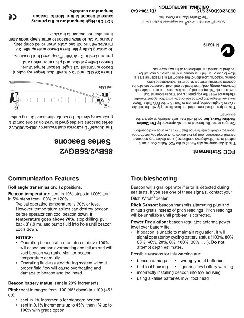
TXu Beacon
The Subsite®Electronics dual frequency TXu beacon is
designed to function as one part of the TK Series HDD
Guidance System for horizontal directional drilling units.
These 12 kHz and 29 kHz dual frequency beacons
transmit roll angle, beacon temperature, beacon battery
status, and pitch information.
To prolong battery life, these beacons sleep after 20
minutes with no roll and wake when rolled completely
around twice. To allow beacon to enter sleep mode after
5 minutes, roll beacon to 5 o’clock.
Communication Features
Roll angle transmission: 24 positions.
Beacon temperature: sent in 3°C/5.4°F steps.
NOTICE:
• Operating beacon at temperatures above 80°C/
176°F will cause beacon overheating and failure
and will void beacon warranty. If temperature
goes above 70°C/158°F, stop drilling, pull back 3’
(.9 m), and pump fluid into hole until beacon cools
down.Monitor beacon temperature carefully.
• Operating fluid-assisted drilling system without
proper fluid flow will cause overheating and
damage to beacon and tool head.
Beacon battery status: sent in 25% increments.
Pitch: sent in ranges from -100% (45° down) to +100%
(45° up).
• sent in 0.1% increments up to 45%, then 1% up to
100%.
Troubleshooting
Beacon Signal Error: beacon regulates antenna power
level over battery life.
• If beacon is unable to maintain regulation, it will
indicate a beacon signal error. Do not attempt
depth estimates. See TK manual for further
information.
Possible reasons for this warning are:
• ignoring low battery warning
• wrong type of batteries
• beacon damage
• bad tool housing
• incorrectly installing beacon into tool housing
• using alkaline batteries in AT tool head
Pitch Sensor Error: beacon transmits alternating plus
and minus signals instead of pitch readings.
IMPORTANT: Pitch readings will be unreliable until
the problem is corrected. Return for service if this
error message is received.
NOTICE: High temperature is the primary
cause of beacon failure. Monitor beacon
temperature carefully.
ss1134a
ORIGINAL INSTRUCTION
Subsite®and Ditch Witch® are registered trademarks of
The Charles Machine Works, Inc.
TX/u 5/15 (E) 790-1081

Install Batteries and
Select Frequency
1. Unscrew cap.
2. Check for and correct the
following conditions:
• dirty or damaged threads.
• missing, dirty or worn foam
washer on battery cap and
bottom of battery chamber.
• missing, worn or damaged
springs.
• missing, damaged or dirty
o-ring. Clean or replace as
needed.
3. Insert, positive end first, one Power Stick battery (p/
n 222-1369) or one Electrochem CC 3.67 V Lithium.
•To select 12 kHz frequency, hold beacon vertical
to the ground with the end slot pointed toward the
ground.
•To select 29 kHz frequency, hold beacon vertical
to the ground with the end slot pointing toward the
sky.
4. Install batteries. Keep beacon steady while hand
tightening cap firmly. Use tracker to confirm beacon
is functioning.
Note: Frequencies may be switched after they are
initially set. See “Switch Frequency While Drilling”
section.
IMPORTANT: For maximum performance, use only
Power Stick battery (p/n 222-1369) or Electrochem CC
3.67 V Lithium batteries. Standard “C” cell alkaline
batteries can cause intermittent operation and beacon
signal errors.
Test Operation
Use a tracker to test beacon function before leaving for
jobsite and after every battery change.
To test beacon function:
1. Turn on tracker, select frequency (if equipped with
dual frequency) and adjust gain so that signal
strength is approximately 50% (see tracker
operator’s manual).
2. Roll beacon and look at display for corresponding
roll positions.
3. Tilt beacon and look at display for corresponding
pitch positions.
4. Check beacon battery status and temperature.
For best results, replace batteries daily. (Using weak
batteries in beacon can cause erratic signal and/or
damage.) Recalibrate tracker to beacon after changing
batteries.
Install Beacon into Tool Housing
The TXu beacon is designed to fit into all housings that
will accept a 1.25” (3.2 cm) diameter x 15” (38.1 cm)
length transmitter/beacon or larger. Some housings
require isolators or adapters. Refer to the appropriate
installation guide for each housing for proper installation.
IMPORTANT: Check beacon operation and condition of
both isolators (if used) before installing beacon into tool
housing.
1. Lay beacon into tool housing with end slot toward bit
and aligned with tab in the housing or lid.
2. Check for proper beacon alignment by rolling
housing on the ground and watching for
corresponding roll positions on tracker display.
IMPORTANT: After installing beacon into tool housing,
calibrate tracker for each frequency before drilling.
Calibrate Tracker to Beacon
1. Select beacon frequency.
2. Install beacon into drill head and place on ground
exactly 10’ (3 m) away from tracker. Make sure no
metal objects including drilling unit and drill pipe are
within 20’ (6 m) of tracker and toolhead.
3. Position tracker parallel to center of drill head.
4. Turn tracker on and enter the depth calibration
menu. See tracker manual for details.
5. Verify calibration by moving tracker 15’ (4.5 m) away
from tool head. Check depth. If reading is not 15’
(4.5 m), recalibrate tracker.
IMPORTANT: When verifying calibration above
ground, be sure to stay in the calibration screen.
6. Repeat for other frequency.
Switch Frequency While Drilling
1. Allow beacon to go to sleep.
2. Rotate beacon within a minute of it going to sleep to
switch frequency.
If beacon is rotated after it has been asleep longer
than a minute, the frequency will not change.
3. Change and verify frequency on the tracker.
This unit covered by one or more of the following patents: U.S.
5,880,680; 7,251,567; 7,786,731; 7,999,551; 8,497,684; GB
2439495, UK0846841; other US and foreign applications
pending.

Isolation Method in DHT Housings
Beacon/sonde/transmitter housings are designed to
accept various sizes of beacons, sondes, or transmitters
with and/or without end isolators.
Use one of the appropriate isolation methods below for
optimal performance and wear.
Use the table below to determine which parts are required for
the appropriate housing.
Third Party Housing
Housing is designed for multiple beacon sizes. The slots
are open.
1. If space allows, install a nylon sleeve (2), heat shrink
tubing, or electrical tape to cover the entire length of
the beacon.
2. If applicable, install end isolators (3,1).
Ditch Witch®86B Housing
Housing is designed for 86B size beacons. The slots are
epoxied.
1. Install end isolators (3,1).
Low Profile AT Housing
Housing (400-1200) is designed to accept 1.25”
diameter x 15” long beacons. It does not have space for
the nylon sleeve. In “heavy metal” beacons housings
such as this, a lower frequency may be more effective.
1. Wrap two to four layers of electrical tape (4) in the
positions shown (or wrap the entire length of the
beacon).
IMPORTANT: Ensure proper frequency is in use for
present conditions.
Remove Beacon from Tool Housing
IMPORTANT: Remove beacon before mud in beacon
chamber hardens and locks beacon into housing.
1. Remove beacon from tool housing.
IMPORTANT: If beacon will not come out, do not
use force. Try soaking housing in water until dried
mud inside housing softens. If beacon still will not
come out, contact your Ditch Witch®dealer for
advice.
2. Clean beacon and remove battery.
3. Wash and lubricate tool housing.
Ref. P/N Description
1 908-4304 isolator, 1.5” univ front
2 906-2702 univ sonde sleeve
3 908-4295 isolator, univ rear
4 electrical tape
e17om052w.eps
123
e17om053w.eps
13
e17om055w.eps
44
Table of contents
Other Subsite Security System manuals