Subzero BI-36U/O User manual

Page 2
1-10
7040127 - Revision C - May, 2015
General Information Built-In (BI) Series
Built-In (BI) Series (SWS #4250000)
(SWS #4250000)
Model BI-36U
BI-36U/O
BI-36U/S
MODEL DESCRIPTION
Built-In Series, 36” Wide, Over/Under, Overlay
Door Trim (No Handles), Panel Grille (Standard)
Built-In Series, 36” Wide, Over/Under, Classic
Stainless Steel Wrapped Doors, Stainless Steel
Grille (Standard)
NOTE: Framed Design application is only avail-
able with use of Sales Accessory Handles and
grille panel.
Model BI-36UG
BI-36UG/O
BI-36UA/O
BI-36UG/S
BI-36UA/S
MODEL DESCRIPTION
Built-In Series, 36” Wide, Over/Under, Glass
Refrigerator Door, Overlay Door Trim (No
Handles), Panel Grille (Standard)
(Same as above with High Altitude Glass)
Built-In Series, 36” Wide, Over/Under, Glass
Refrigerator Door, Classic Stainless Steel
Wrapped Doors, Stainless Steel Grille (Standard)
(Same as above with High Altitude Glass)
NOTE: Framed Design application is only avail-
able with use of Sales Accessory Handles and
grille panel.
Model BI-36UFD
BI-36UFD/O
BI-36UFD/S
MODEL DESCRIPTION
Built-In Series, 36” Wide, Over/Under, French
Doors, Overlay Door Trim (No Handles), Panel
Grille (Standard)
Built-In Series, 36” Wide, Over/Under, French
Doors, Classic Stainless Steel Wrapped Doors,
Stainless Steel Grille (Standard)
NOTE: Framed Design application is only avail-
able with use of Sales Accessory Handles and
grille panel.

Page 3
1-11 7040127 - Revision C - May, 2015
Built-In (BI) Series
Built-In (BI) Series (SWS #4250000)
(SWS #4250000) General Information
Model BI-42S
BI-42S/O
BI-42S/S
MODEL DESCRIPTION
Built-In Series, 42” Wide, Side-by-Side, Overlay
Door Trim (No Handles), Panel Grille (Standard)
Built-In Series, 42” Wide, Side-by-Side, Classic
Stainless Steel Wrapped Doors, Stainless Steel
Grille (Standard)
NOTE: Framed Design application is only avail-
able with use of Sales Accessory Handles and
grille panel.
Model BI-42SD
BI-42SD/O
BI-42SD/S
MODEL DESCRIPTION
Built-In Series, 42” Wide, Side-by-Side, External
Ice/Water Dispenser, Overlay Door Trim (No
Handles), Panel Grille (Standard)
Built-In Series, 42” Wide, Side-by-Side, External
Ice/Water Dispenser, Classic Stainless Steel
Wrapped Doors, Louver Grille (Standard)
NOTE: Framed Design application is only avail-
able with use of Sales Accessory Handles and
grille panel.
Model BI-36S
BI-36S/O
BI-36S/S
MODEL DESCRIPTION
Built-In Series, 36” Wide, Side-by-Side, Overlay
Door Trim (No Handles), Panel Grille (Standard)
Built-In Series, 36” Wide, Side-by-Side, Classic
Stainless Steel Wrapped Doors, Stainless Steel
Grille (Standard)
NOTE: Framed Design application is only avail-
able with use of Sales Accessory Handles and
grille panel.

Page 4
1-12
7040127 - Revision C - May, 2015
General Information Built-In (BI) Series
Built-In (BI) Series (SWS #4250000)
(SWS #4250000)
Model BI-48S
BI-48S/O
BI-48S/S
MODEL DESCRIPTION
Built-In Series, 48” Wide, Side-by-Side, Overlay
Door Trim (No Handles), Panel Grille (Standard)
Built-In Series, 48” Wide, Side-by-Side, Classic
Stainless Steel Wrapped Doors, Stainless Steel
Grille (Standard)
NOTE: Framed Design application is only avail-
able with use of Sales Accessory Handles and
grille panel.
DISPENSER
Model BI-42SID
BI-42SID/O
BI-42SID/S
MODEL DESCRIPTION
Built-In Series, 42” Wide, Side-by-Side, Internal
Ice/Water Dispenser, Overlay Door Trim (No
Handles), Panel Grille (Standard)
Built-In Series, 42” Wide, Side-by-Side, Internal
Ice/Water Dispenser, Classic Stainless Steel
Wrapped Doors, Louver Grille (Standard)
NOTE: Framed Design application is only avail-
able with use of Sales Accessory Handles and
grille panel.
Model BI-42UFD
BI-42UFD/O
BI-42UFD/S
MODEL DESCRIPTION
Built-In Series, 42” Wide, Over/Under, French
Doors, Overlay Door Trim (No Handles), Panel
Grille (Standard)
Built-In Series, 42” Wide, Over/Under, French
Doors, Classic Stainless Steel Wrapped Doors,
Stainless Steel Grille (Standard)
NOTE: Framed Design application is only avail-
able with use of Sales Accessory Handles and
grille panel.

Page 5
1-13 7040127 - Revision C - May, 2015
Built-In (BI) Series
Built-In (BI) Series (SWS #4250000)
(SWS #4250000) General Information
Model BI-48SID
BI-48SID/O
BI-48SID/S
MODEL DESCRIPTION
Built-In Series, 48” Wide, Side-by-Side, Internal
Ice/Water Dispenser, Overlay Door Trim (No
Handles), Panel Grille (Standard)
Built-In Series, 48” Wide, Side-by-Side, Internal
Ice/Water Dispenser, Classic Stainless Steel
Wrapped Doors, Louver Grille (Standard)
NOTE: Framed Design application is only avail-
able with use of Sales Accessory Handles and
grille panel.
Model BI-48SD
BI-48SD/O
BI-48SD/S
MODEL DESCRIPTION
Built-In Series, 48” Wide, Side-by-Side, Ice/Water
Dispenser, Overlay Door Trim (No Handles),
Panel Grille (Standard)
Built-In Series, 48” Wide, Side-by-Side, Ice/Water
Dispenser, Classic Stainless Steel Wrapped
Doors, Louver Grille (Standard)
NOTE: Framed Design application is only avail-
able with use of Sales Accessory Handles and
grille panel.

Page 6
2-2
7040127 - Revision C - May, 2015
Installation Information Built-In (BI) Series
Built-In (BI) Series (SWS #4250000)
(SWS #4250000)
INSTALLATION CONSIDERATIONS
This section uses some of the information in the BI Series Installation Guide to address common installation issues
seen by Service Technicians. Improper installation, though not a valid service issue, has the potential to lead to a
call for service. Installation related complaints could include, but are not limited to: Unit leveling, unit movement,
door misalignment, improper door and drawer sealing, internal frost or condensation, exterior condensation, warm
compartment temperatures, etc.
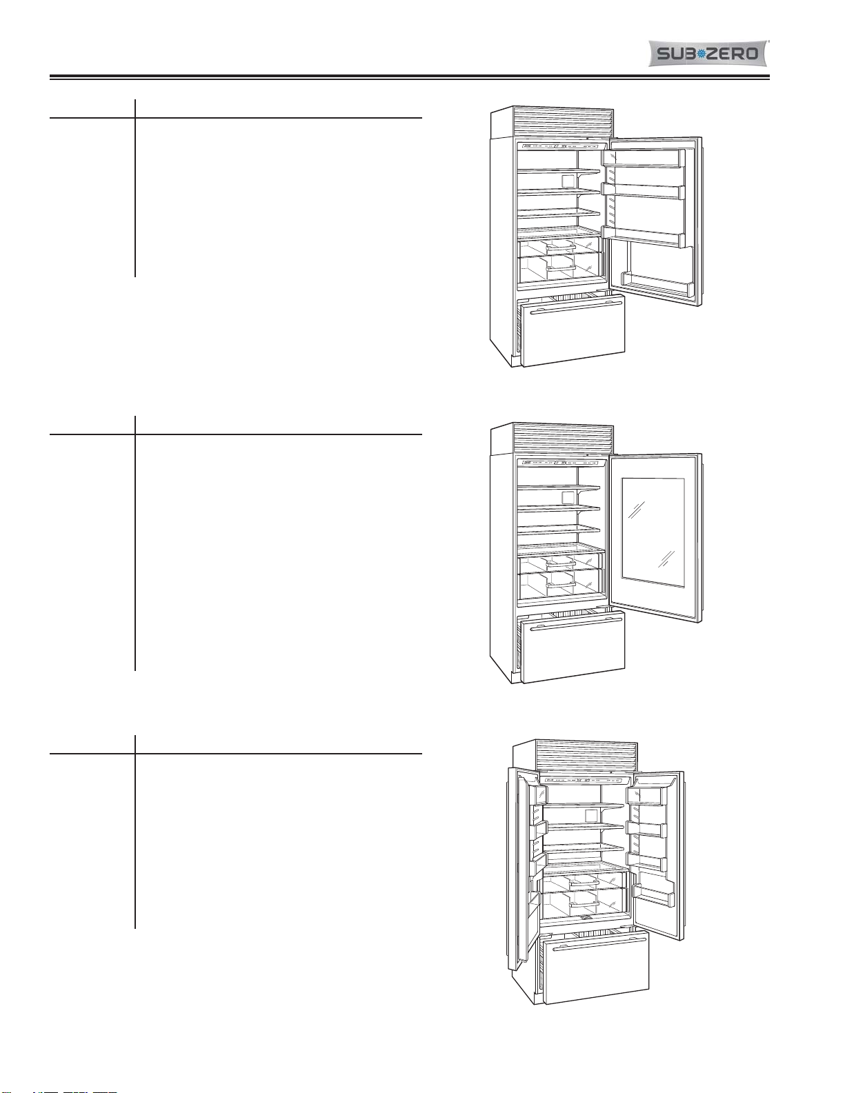
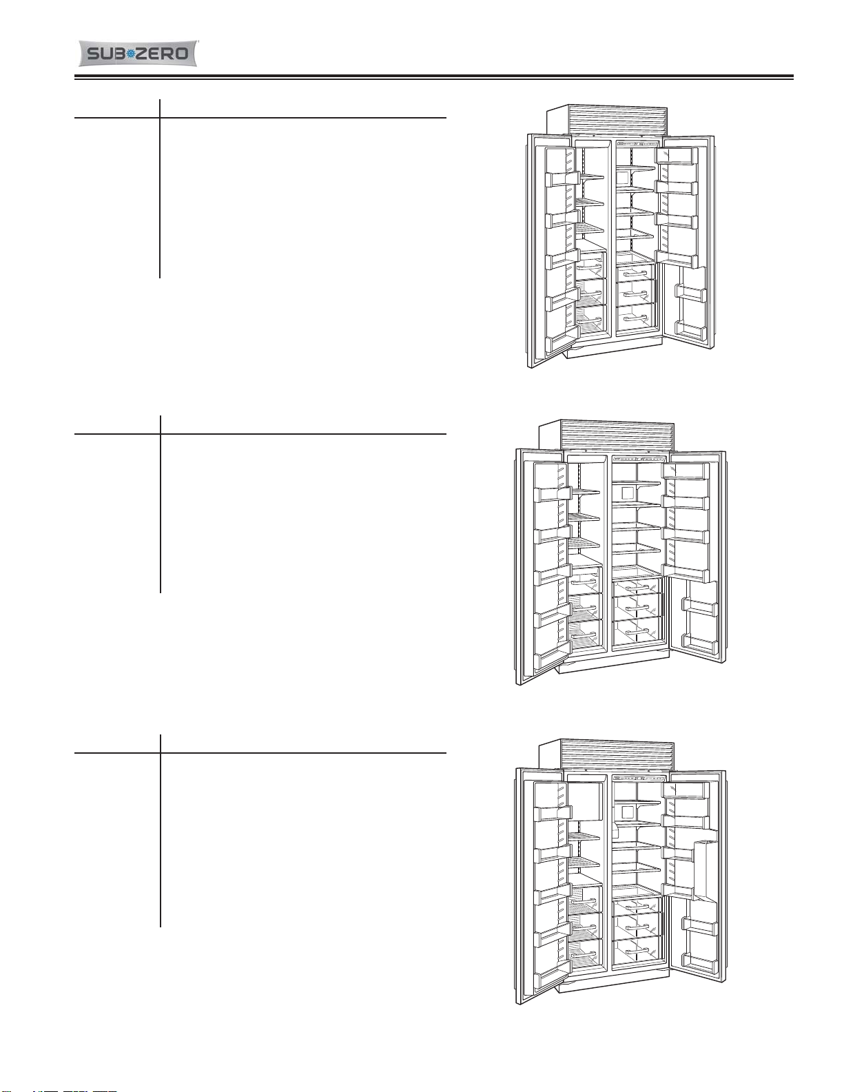
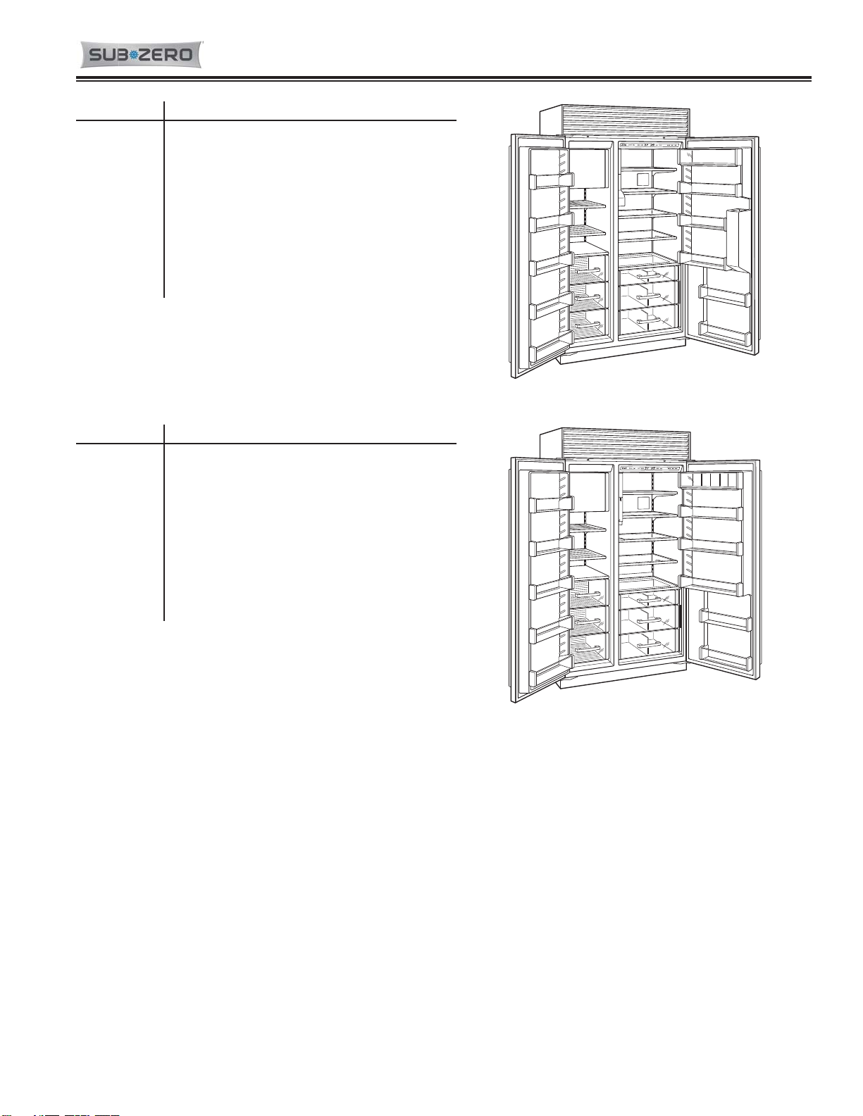
The Built-In line offers the following design alternatives - framed, overlay and stainless steel models. The overlay
design has two possible installation applications - standard overlay and flush inset. Each of these design options
has specific installation requirements, which means it is vital that the unit match the planning and space needs.
NOTE: If additional installation information is needed, refer to the complete Installation Guide, or contact Sub-Zero
Service Department.
Tools and Materials Required
The following is a list of tools and materials that will assist in a proper installation.
• Phillips screwdriver set
• Slotted screwdriver set
• 6-Lobe, Torx type drive screwdriver set (Specific sizes, T-10, T-20 and T-25)
• 4' (1.2 m) of 1/4" copper tubing and saddle
• valve for the water line—part #4200880
• (do not use self-piercing valves)
• Copper tubing cutter
• Level - 2' (.6 m) and 4' (1.2 m) recommended
• Appliance Dolly able to support 700 lbs (317 kg) and adequate manpower to handle the weight of the unit
• Various sized pliers
• Wrench set
• Allen wrench set
• 5/16" hex bolt nut driver
• Crescent wrenches
• Cordless drill and assorted drill bits
• Masonite, plywood, 1/8" pressed fiberboard, cardboard or other suitable material to protect finished flooring
• Appropriate materials to cover and protect the home and its furnishings during installation
Site Preparation
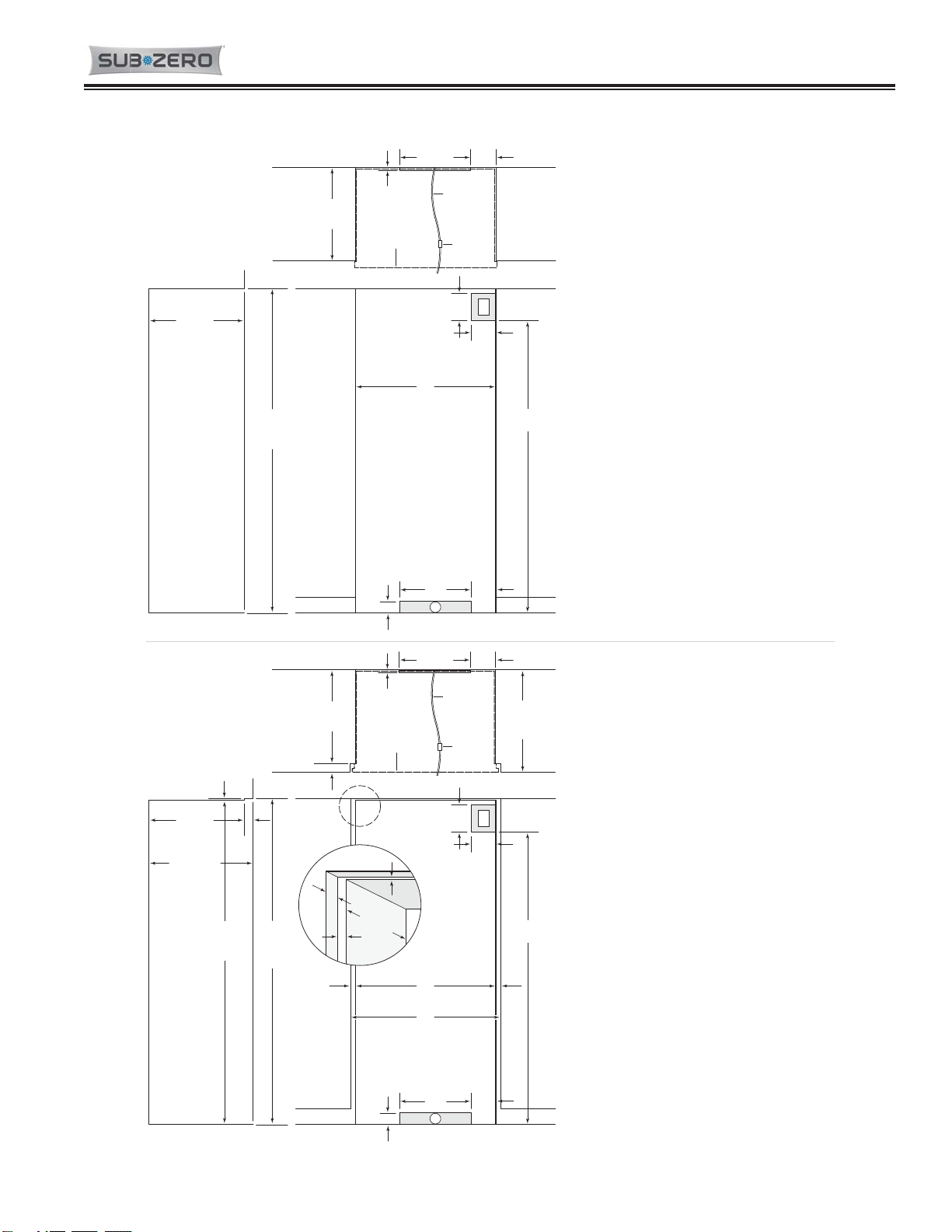
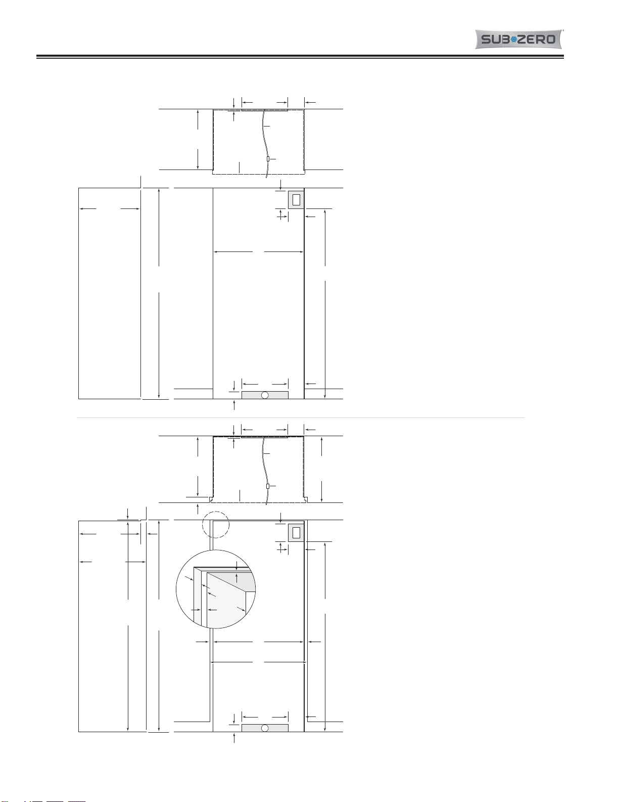
The finished rough opening where the Built-In unit is to be installed must be properly prepared. Refer to the Finished
Rough Opening Specifications for the specific model on the following pages. The specifications for the framed, over-
lay and stainless steel applications are identical. The Finished Rough Opening Specifications are different for the
flush inset application, whether using custom panels or Sub-Zero accessory stainless flush inset panels. Make sure
that the rough opening dimensions, door swing clearance, electrical service and plumbing are correct for the model
being installed.
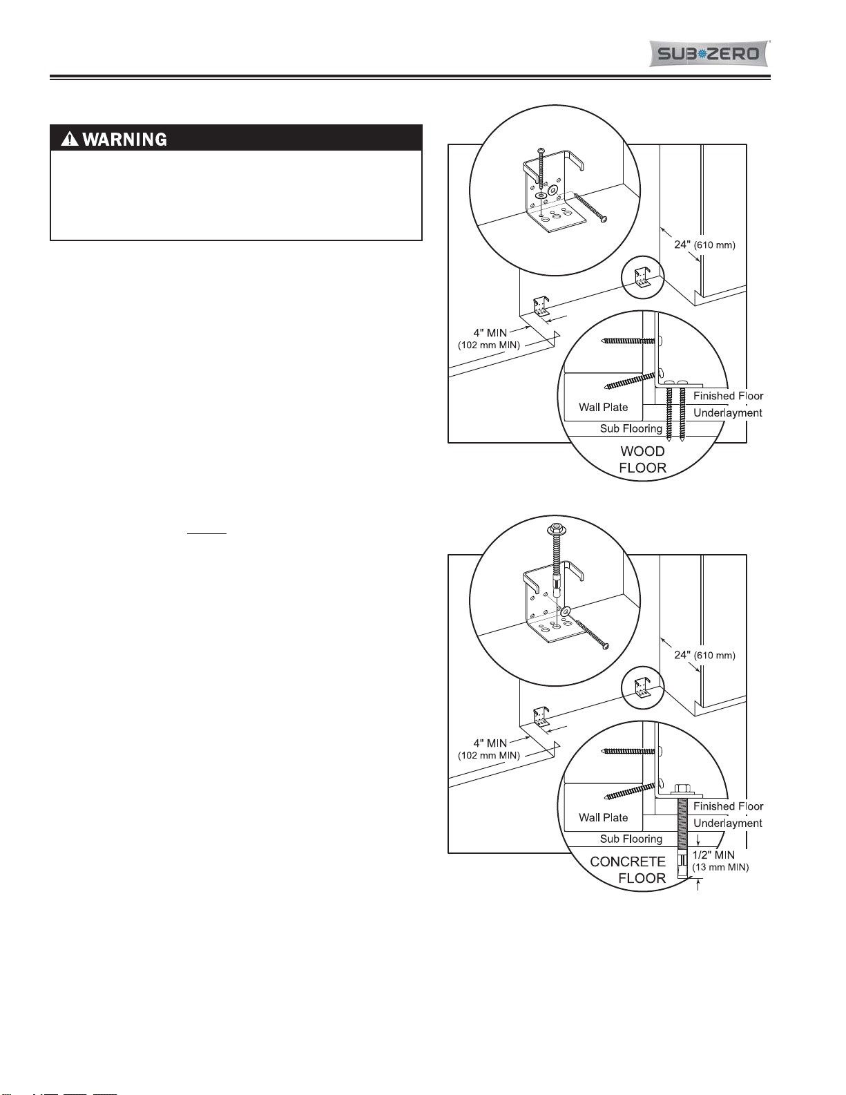
If installing two Built-In units side by side in the framed, overlay or stainless steel application, a separating filler strip
is recommended. Add the filler strip width to the finished rough opening dimension, and ALWAYS complete the
installation with the Anchoring Kit components.
For installation of two Built-In units side by side in the flush inset application, a dual installation kit will be necessary.
IMPORTANT NOTE: Built-in units installed side by side in the flush inset application cannot use the standard Sub-
Zero accessory overlay panels, and must have opposing hinges.
IMPORTANT NOTE: To operate properly, the door must open a minimum of ninety (90) degrees. Use a minimum 3"
(76) filler in corner installations to assure a ninety (90) degree door opening. Allow enough clearance in front of the
unit for full door swing.
IMPORTANT NOTE: Make sure the floor under the unit is level with the surrounding finished floor.

Page 7
2-3 7040127 - Revision C - May, 2015
Built-In (BI) Series
Built-In (BI) Series (SWS #4250000)
(SWS #4250000) Installation Information
INSTALLATION SPECIFICATIONS
Over-and-Under Models —
Framed, Overlay (non-flush inset) and
Stainless Steel
A
Model BI-30U 29
1
/
2
" (749)
Model BI-30UG 29
1
/
2
" (749)
Model BI-36U 35
1
/
2
" (902)
INSTALLATION SPECIFICATIONS
Over-and-Under Models —
Flush Inset Application
AB
Model BI-30U 29
1
/
2
" (749) 32" (813)
Model BI-30UG 29
1
/
2
" (749) 32" (813)
Model BI-36U 35
1
/
2
" (902) 38" (965)
Dimensions in parentheses are in
millimeters unless otherwise specified.
751/2"
(1918)
7"
(178)
6"
(152)
E
LOCATE
ELECTRICAL
WITHIN
SHADED AREA
18"
(457)
W
LOCATE WATER SUPPLY
WITHIN SHADED AREA
6"
(152)
FRONT VIEWSIDE VIEW
833/4"
(2127)
OPENING
HEIGHT
A
OPENING WIDTH
3" (76)
24" (610)
OPENING
DEPTH
1/2"
(13)
18" (457)
*
6"
(152)
24" (610)
OPENING
DEPTH
SHUT-OFF
VALVE
OUTLINE OF
FRAMED, OVERLAY
OR STAINLESS
STEEL MODEL
TOP VIEW
*ANTI-TIP
BRACKET MUST NOT
INTERFERE
WITH WATER LINE.
REFER TO INSTALLATION
INSTRUCTIONS FOR COMPLETE
DETAILS.
EXTEND WATER LINE APPROX
36" (914) FROM BACK WALL.
WATER LINE
751/2"
(1918)
7"
(178)
6"
(152)
E
LOCATE
ELECTRICAL
WITHIN
SHADED AREA
1/2"
(13)
18" (457)
*
6"
(152)
24" (610)
OPENING
DEPTH
263/16"
(665)
FLUSH INSET
DEPTH
SHUT-OFF
VALVE
OUTLINE
OF FLUSH INSET
APPLICATION WITH
3/4"(19) PANEL
18"
(457)
W
LOCATE WATER SUPPLY
WITHIN SHADED AREA
6"
(152)
FRONT VIEWSIDE VIEW
TOP VIEW
833/4"
(2127)
OPENING
HEIGHT
84"
(2134)
FLUSH
INSET
HEIGHT
1/4"(6) 23/16"
(56)
**
3" (76)
A
OPENING WIDTH
B
FLUSH INSET WIDTH
11/4"
(32)
11/4"
(32)
23/16"
(56)
**
24" (610)
OPENING
DEPTH
263/16"(665)
FLUSH INSET
DEPTH
*ANTI-TIP
BRACKET MUST NOT
INTERFERE
WITH WATER LINE.
REFER TO INSTALLATION
INSTRUCTIONS FOR COMPLETE
DETAILS.
**ASSUMES 3/4"(19) PANEL
THICKNESS.
EXTEND WATER LINE APPROX
36" (914) FROM BACK WALL.
WATER LINE
1/4"
(6)
11/4"
(32)
FLUSH INSET
DETAIL
23/16"
(56) 24" (610)
OPENING
DEPTH
Model BI-36UFD 35
1
/
2
" (902)
Model BI-36UG 35
1
/
2
" (902)
Model BI-36UFD 35
1
/
2
" (902) 38" (965)
Model BI-36UG 35
1
/
2
" (902) 38" (965)
Model BI-42UFD 41
1
/
2
" (1054)
Dimensions are for finished rough openings.
Model BI-42UFD 41
1
/
2
" (1054) 44" (1118)
Dimensions are for finished rough openings.
Finished Rough Opening Specifications (30”, 36” and 42” Over / Under Models)

Page 8
2-4
7040127 - Revision C - May, 2015
Installation Information Built-In (BI) Series
Built-In (BI) Series (SWS #4250000)
(SWS #4250000)
INSTALLATION SPECIFICATIONS
All Refrigerator / All Freezer Models —
Framed, Overlay (non-ush inset) and
Stainless Steel
A
Model BI-36R 35
1
/
2
" (902)
Model BI-36RG 35
1
/
2
" (902)
Model BI-36F 35
1
/
2
" (902)
Dimensions are for nished rough openings.
Models BI-36R and BI-36RG will not require the
water line connection.
INSTALLATION SPECIFICATIONS
All Refrigerator / All Freezer Models —
Flush Inset Application
AB
Model BI-36R 35
1
/
2
" (902) 38" (965)
Model BI-36RG 35
1
/
2
" (902) 38" (965)
Model BI-36F 35
1
/
2
" (902) 38" (965)
Dimensions are for nished rough openings.
Models BI-36R and BI-36RG will not require the
water line connection.
75 1/2"
(1918)
7"
(178)
6"
(152)
E
LOCATE
ELECTRICAL
WITHIN
SHADED AREA
18"
(457)
W
LOCATE WATER SUPPLY
WITHIN SHADED AREA
6"
(152)
FRONT VIEWSIDE VIEW
83 3/4"
(2127)
OPENING
HEIGHT
A
OPENING WIDTH
3" (76)
24" (610)
OPENING
DEPTH
1/2"
(13)
18" (457)
*
6"
(152)
24" (610)
OPENING
DEPTH
SHUT-OFF
VALVE
OUTLINE OF
FRAMED, OVERLAY
OR STAINLESS
STEEL MODEL
TOP VIEW
*ANTI-TIP
BRACKET MUST NOT
INTERFERE
WITH WATER LINE.
REFER TO INSTALLATION
INSTRUCTIONS FOR COMPLETE
DETAILS.
EXTEND WATER LINE APPROX
36" (914) FROM BACK WALL.
WATER LINE
75 1/2"
(1918)
7"
(178)
6"
(152)
E
LOCATE
ELECTRICAL
WITHIN
SHADED AREA
1/2"
(13)
18" (457)
*
6"
(152)
24" (610)
OPENING
DEPTH
26 3/16"
(665)
FLUSH INSET
DEPTH
SHUT-OFF
VALVE
OUTLINE
OF FLUSH INSET
APPLICATION WITH
3/4"(19) PANEL
18"
(457)
W
LOCATE WATER SUPPLY
WITHIN SHADED AREA
6"
(152)
FRONT VIEWSIDE VIEW
TOP VIEW
83 3/4"
(2127)
OPENING
HEIGHT
84"
(2134)
FLUSH
INSET
HEIGHT
1/4"(6) 23/16"
(56)
**
3" (76)
A
OPENING WIDTH
B
FLUSH INSET WIDTH
11/4"
(32)
11/4"
(32)
23/16"
(56)
**
24" (610)
OPENING
DEPTH
26 3/16"(665)
FLUSH INSET
DEPTH
*ANTI-TIP
BRACKET MUST NOT
INTERFERE
WITH WATER LINE.
REFER TO INSTALLATION
INSTRUCTIONS FOR COMPLETE
DETAILS.
**ASSUMES 3/4"(19) PANEL
THICKNESS.
EXTEND WATER LINE APPROX
36" (914) FROM BACK WALL.
WATER LINE
1/4"
(6)
11/4"
(32)
FLUSH INSET
DETAIL
23/16"
(56) 24" (610)
OPENING
DEPTH
Dimensions in parentheses are in
millimeters unless otherwise specied.
Finished Rough Opening Specifications (36” All Refrigerator and All Freezer Models)

Page 9
2-5 7040127 - Revision C - May, 2015
Built-In (BI) Series
Built-In (BI) Series (SWS #4250000)
(SWS #4250000) Installation Information
Dimensions in parentheses are in
millimeters unless otherwise specified.
751/2"
(1918)
7"
(178)
6"
(152)
E
LOCATE
ELECTRICAL
WITHIN
SHADED AREA
18"
(457)
W
LOCATE WATER SUPPLY
WITHIN SHADED AREA
6"
(152)
FRONT VIEWSIDE VIEW
833/4"
(2127)
OPENING
HEIGHT
A
OPENING WIDTH
3" (76)
24" (610)
OPENING
DEPTH
1/2"
(13)
18" (457)
*
6"
(152)
24" (610)
OPENING
DEPTH
SHUT-OFF
VALVE
OUTLINE OF
FRAMED, OVERLAY
OR STAINLESS
STEEL MODEL
TOP VIEW
*ANTI-TIP
BRACKET MUST NOT
INTERFERE
WITH WATER LINE.
REFER TO INSTALLATION
INSTRUCTIONS FOR COMPLETE
DETAILS.
EXTEND WATER LINE APPROX
36" (914) FROM BACK WALL.
WATER LINE
751/2"
(1918)
7"
(178)
6"
(152)
E
LOCATE
ELECTRICAL
WITHIN
SHADED AREA
1/2"
(13)
18" (457)
*
6"
(152)
24" (610)
OPENING
DEPTH
263/16"
(665)
FLUSH INSET
DEPTH
SHUT-OFF
VALVE
OUTLINE
OF FLUSH INSET
APPLICATION WITH
3/4"(19) PA N E L
18"
(457)
W
LOCATE WATER SUPPLY
WITHIN SHADED AREA
6"
(152)
FRONT VIEWSIDE VIEW
TOP VIEW
833/4"
(2127)
OPENING
HEIGHT
84"
(2134)
FLUSH
INSET
HEIGHT
1/4"(6) 23/16"
(56)
**
3" (76)
A
OPENING WIDTH
B
FLUSH INSET WIDTH
11/4"
(32)
11/4"
(32)
23/16"
(56)
**
24" (610)
OPENING
DEPTH
263/16"(665)
FLUSH INSET
DEPTH
*ANTI-TIP
BRACKET MUST NOT
INTERFERE
WITH WATER LINE.
REFER TO INSTALLATION
INSTRUCTIONS FOR COMPLETE
DETAILS.
**ASSUMES 3/4"(19) PANEL
THICKNESS.
EXTEND WATER LINE APPROX
36" (914) FROM BACK WALL.
WATER LINE
1/4"
(6)
11/4"
(32)
FLUSH INSET
DETAIL
23/16"
(56) 24" (610)
OPENING
DEPTH
INSTALLATION SPECIFICATIONS
Side-by-Side Models —
Framed, Overlay (non-flush inset) and
Stainless Steel
A
Model BI-36S 35
1
/
2
" (902)
Model BI-42S 41
1
/
2
" (1054)
Model BI-42SD 41
1
/
2
" (1054)
INSTALLATION SPECIFICATIONS
Side-by-Side Models —
Flush Inset Application
AB
Model BI-36S 35
1
/
2
" (902) 38" (965)
Model BI-42S 41
1
/
2
" (1054) 44" (1118)
Model BI-42SD 41
1
/
2
" (1054)
Model BI-42SID 41
1
/
2
" (1054)
Model BI-48S 47
1
/
2
" (1207)
Model BI-48SD 47
1
/
2
" (1207)
Model BI-48SID 47
1
/
2
" (1207)
Dimensions are for finished rough openings.
Model BI-42SD 41
1
/
2
" (1054) 44" (1118)
Model BI-42SID 41
1
/
2
" (1054) 44" (1118)
Model BI-48S 47
1
/
2
" (1207) 50" (1270)
Model BI-48SD 47
1
/
2
" (1207) 50" (1270)
Model BI-48SID 47
1
/
2
" (1207) 50" (1270)
Dimensions are for finished rough openings.
Finished Rough Opening Specifications (36”, 42” and 48” Side-by-Side Models)

Page 10
2-6
7040127 - Revision C - May, 2015
Installation Information Built-In (BI) Series
Built-In (BI) Series (SWS #4250000)
(SWS #4250000)
Anti-Tip Bracket Installation
Figure 2-4
Figure 2-5
THE UNIT COULD TIP FORWARD UNDER CERTAIN
LOAD CONDITIONS. FAILURE TO INSTALL BOTH
ANTI-TIP BRACKETS AND EXTEND LEVELERS TO
FLOOR ACCORDING TO INSTALLATION MANUAL
COULD RESULT IN SERIOUS INJURY OR DEATH.
IMPORTANT NOTE: Placement of the two anti-tip brackets
is critical. They must be installed exactly 24" (610 mm)
from the front of the rough opening to the back of the brack-
ets and a minimum of 4" (102 mm) from the sides of the
rough opening. This depth will increase to 26-3/16" (665
mm) for a flush inset installation based on 3/4" (19 mm)
thick decorative panels. Failure to properly position the
anti-tip brackets will prevent them from engaging the unit
should it tip forward.
Standard Installation Procedure:
The two anti-tip brackets must be located 24''(610 mm)
back from front of rough opening and a minimum of 4” (102
mm) from sides of rough opening. This will ensure that ant-
tip brackets properly engage anti-tip bar at back of unit.
NOTE: Both brackets MUST be used.
Wood Floor Applications: (See Figure 2-4)
After properly locating anti-tip brackets in rough opening,
drill pilot holes 3/16'' diameter maximum. Then, use the
#12 X 2-1/2” PH Pan HD Zinc Screws and #12 Flat
Washers to secure the brackets in place.
NOTES:
• Make sure screws penetrate flooring material and wall
stud or wall plate a minimum of 3/4'' (19 mm).
• If #12 X 2-1/2'' screws do not hit a wall stud or the wall
plate in any of the brackets back holes, use the #8-18 X
1-1/4” PH Truss HD Screws and #12 Flat Washers with
the Nylon Zip-It Wall Anchors.
Concrete Floor Applications: (See Figure 2-5)
After properly locating anti-tip brackets in rough opening,
drill pilot holes 3/16'' diameter maximum in the wall studs
and/or wall plate, then drill 3/8” diameter holes into the con-
crete a minimum of 1/2“ (13 mm) deep. Then, use the #12
X 2-1/2” PH Pan HD Zinc Screws and #12 Flat Washers to
secure the brackets to the wall, and use the 3/8”-16 X 3-
3/4” Wedge Anchors to secure the brackets to the floor.
NOTES:
• Make sure screws penetrate wall stud or wall plate a
minimum of 3/4'' (19 mm).
• If #12 X 2-1/2'' screws do not hit a wall stud or the wall
plate in any of the brackets back holes, use the#8-18 X
1-1/4” PH Truss HD Screws and #12 Flat Washers with
the Nylon Zip-It Wall Anchors.

Page 11
2-7 7040127 - Revision C - May, 2015
Built-In (BI) Series
Built-In (BI) Series (SWS #4250000)
(SWS #4250000) Installation Information
Flush Inset Installation Procedure:
The two anti-tip brackets must be located 24''(610 mm)
back from front of rough opening and a minimum of 4” (102
mm) from sides of rough opening. This will ensure that ant-
tip brackets properly engage anti-tip bar at back of unit.
NOTE: Both brackets MUST be used.
Wood Floor Applications: (See Figure 2-6)
After properly locating anti-tip brackets in rough opening,
drill pilot holes 3/16'' diameter maximum. Then, use the
#12 X 2-1/2” PH Pan HD Zinc Screws and #12 Flat
Washers to secure the brackets in place.
NOTES:
• Make sure screws penetrate flooring material and wall
stud or wall plate a minimum of 3/4'' (19 mm).
• If #12 X 2-1/2'' screws do not hit a wall stud or the wall
plate in any of the brackets back holes, use the #8-18 X
1-1/4” PH Truss HD Screws and #12 Flat Washers with
the Nylon Zip-It Wall Anchors.
Concrete Floor Applications: (See Figure 2-7)
After properly locating anti-tip brackets in rough opening,
drill pilot holes 3/16'' diameter maximum in the wall studs
and/or wall plate, then drill 3/8” diameter holes into the con-
crete a minimum of 1/2“ (13 mm) deep. Then, use the #12
X 2-1/2” PH Pan HD Zinc Screws and #12 Flat Washers to
secure the brackets to the wall, and use the 3/8”-16 X 3-
3/4” Wedge Anchors to secure the brackets to the floor.
NOTES:
• Make sure screws penetrate wall stud or wall plate a
minimum of 3/4'' (19 mm).
• If #12 X 2-1/2'' screws do not hit a wall stud or the wall
plate in any of the brackets back holes, use the#8-18 X
1-1/4” PH Truss HD Screws and #12 Flat Washers with
the Nylon Zip-It Wall Anchors.
Figure 2-6
Figure 2-7

Page 12
2-8
7040127 - Revision C - May, 2015
Installation Information Built-In (BI) Series
Built-In (BI) Series (SWS #4250000)
(SWS #4250000)
Electrical Requirements
A 115 V AC, 60 Hz, 15 amp circuit breaker and electri-
cal supply are required. A separate circuit, servicing
only this appliance, is required.
All Sub-Zero Built-In models are equipped with a power
supply cord with a 3-prong grounding plug, which must
be plugged into a mating 3-prong grounding-type wall
receptacle. Follow the National Electrical Code and
local codes and ordinances when installing the recepta-
cle. For location of the electrical supply, refer to the
Finished Rough Opening Specifications illustration for
your specific model.
IMPORTANT NOTE: A ground fault circuit interrupter
(GFCI) is not recommended and may cause interruption
of operation.
DO NOT USE AN EXTENSION CORD OR TWO
PRONG ADAPTER. ELECTRICAL GROUND IS
REQUIRED ON THESE APPLIANCES. DO NOT
REMOVE POWER SUPPLY CORD GROUND
PRONG!
The outlet must be checked by a qualified electri-
cian to be sure that it is wired with the correct
polarity. If the power and neutral polarity are
reversed at the outlet, the appliance will not oper-
ate. Verify that the outlet provides 115 V AC and is
properly grounded.
Plumbing Requirements
All Built-In models with an automatic ice maker are also
equipped with a factory installed, microbiological water
filtration system. This system operates on water pres-
sure between 30 psi (2.1 bar) to 100 psi (6.9 bar).
IMPORTANT NOTE: A reverse osmosis system can be
used, provided there is constant water pressure of 30
psi (2.1 bar) to 100 psi (6.9 bar) supplied to the unit at
all times. If a reverse osmosis system is used, it is rec-
ommended that the water filter be bypassed. Refer to
Water Filter Bypass Plug Installation instructions on the
following page.
Rough in the cold water supply line using 1/4" OD cop-
per line. The water line should be routed up through
the floor within 1/2" (13mm) from the back wall and no
higher than 3" (76mm) off the floor. If the water line
comes through the wall, make sure it is no more than 3"
(76mm) from the floor.
Regardless of the routing, allow 3' (914mm) of excess
copper tubing to remain outside the wall or floor for
easy connection to the unit. The water supply line
should be locate within the shaded area indicated in the
Finished Rough Opening Specifications illustration for
the specific model.
An easily accessible shut-off valve should be used
between the water supply and the unit. Do not use self-
piercing valves. A saddle valve kit (part #4200880) is
available from a Sub-Zero dealer or parts distributor.
It is not recommended that the ice maker be connected
to a softened water supply. Water softener chemicals,
such as salt from a malfunctioning softener, can dam-
age the ice maker and lead to poor ice quality. If a soft-
ened water supply cannot be avoided, be sure that the
water softener is well maintained and operating proper-
ly.
IMPORTANT NOTE: All installations must meet local
plumbing code requirements.

Page 13
2-9 7040127 - Revision C - May, 2015
Built-In (BI) Series
Built-In (BI) Series (SWS #4250000)
(SWS #4250000) Installation Information
Water Line Connections
Approximately 3' (914mm) of 1/4" plastic tubing is con-
nected to the unit with a preassembled 1/4" compres-
sion connection at the end. This tubing is located under
the unit.
The water line fitting connection kit, provided with the
unit, contains a 1/4" compression union fitting for con-
nection to the household water supply line. The com-
pression nut and sleeve should be placed on the water
line and fastened to the connection at the end of the
tubing under the unit. Do not over tighten. Check all
water line fittings for leaks. Make sure that the drain
pan can be installed and/or removed without any water
line interference.
IMPORTANT NOTE: The water line should be purged
prior to final connection to the unit. This will remove
any debris that may be present in the tubing from
installing the new water line.
IMPORTANT NOTE: If a reverse osmosis system
used, it is recommended that the water filter be
bypassed as mentioned earlier is this section.
IMPORTANT NOTE: The customer should be made
aware that the ice maker will not produce ice immedi-
ately, and that the first few batches of ice produced
should be discarded, allowing twenty-four (24) hours for
proper ice production.
IMPORTANT NOTE: Caution must be taken to not
expose the water lines leading to the refrigerator to
freezing temperatures. Failure to do so could cause
damage to the product and home.
Water Filtration System
The water filtration system of Sub-Zero built-in models
supplies filtered water to the ice maker and water dis-
penser (dispenser models) to produce great-tasting
water and ice.
NOTE: When using the water filtration system for the
first time and after filter replacement, it is necessary to
clear any air from the system and allow the filter to
assist in cleaning the water lines. For non-dispenser
models, discard the first two full containers of ice. For
dispenser models, dispense several glasses of water
for a period of two minutes.
If the water filtration system will not be utilized, it can be
placed in water filter bypass mode by removing the fil-
ter. The filter is rated for 750 gallons (2839 L) or one
year, whichever comes first. The indicator will illu-
minate and flash in the control panel display when the
filter needs to be replaced.
Water Filter Replacement
1. To access the water filter, pull out on the bottom
edge of the grille assembly and rotate upward.
2. To remove the old filter, rotate counterclockwise
onequarter turn, then pull out (See Figure 2-8). It is
normal for a small amount of water to drip when the
filter is removed. It should be wiped up with a paper
towel or cloth.
3. Remove the new filter from packaging and remove
plastic cap.
4. Insert the new filter into the manifold and turn clock-
wise.
5. Once the new filter has been installed, press and
hold the water filter reset button for five seconds to
reset (See Figure 2-9).
WATER FILTER
WATER FILTER
RESET BUTTON
WATER
FILTER
Figure 8. Filter Removal Figure 9. Filter Reset

Page 14
2-10
7040127 - Revision C - May, 2015
Installation Information Built-In (BI) Series
Built-In (BI) Series (SWS #4250000)
(SWS #4250000)
Leveling the Unit
Once the unit is in position, the front leveling legs must
be extended down to the floor by turning them clock-
wise. The front leveling legs are also used to make
front height adjustments, turn the leveling legs clock-
wise to raise the unit and counterclockwise to lower it.
The rear height adjustment can be performed at the
front of the base using a 5/16" socket to turn the adjust-
ing bolt that reaches to rear leveler/roller assembly.
Turn the 5/16" hex bolt clockwise to raise the rear of the
unit or counterclockwise to lower it.
When the unit is leveled properly, door and/or drawer
adjustments are less likely to be necessary. Refer to the
illustration below for location of the rear roller base
adjustment.
IMPORTANT NOTE: Be sure to reference “level” of the
unit to the floor, not “squareness” of the unit to the sur-
rounding cabinetry. This could affect the operation of
the unit, such as door closing.
REAR
ADJUSTING
BOLT
FRONT
LEVELING LEG
UNIT BASE ASSEMBLY
REAR
ROLLER / LEVELING
ASSEMBLY
Figure 2-11. Unit Leveling
Door Adjustments
The doors on the Built-In Series side-by-side and single
door models can be adjusted in three ways: up and
down, side to side, and in and out. The doors on over /
under models can be adjusted in two ways: side to
side, and in and out.
IMPORTANT NOTE: Door adjustments should only be
performed after the unit is installed and properly lev-
eled.
Door Height Adjustment Procedure:
Using a 1/4" allen wrench, turn the bottom hinge
adjuster bolt clockwise to raise the door and counter-
clockwise to lower the door. (See Figure 2-12)
DOOR
HINGE ADJUSTER BOLT
Figure 2-12. Door Height Adjustment

Page 15
2-11 7040127 - Revision C - May, 2015
Built-In (BI) Series
Built-In (BI) Series (SWS #4250000)
(SWS #4250000) Installation Information
Side to Side and In and Out Adjustment Procedure:
IMPORTANT NOTE: Side to side and in and out
adjustments only affect the top of the door. The bottom
hinge is stationary, except for up and down adjust-
ments.
1. Slightly loosen the two upper cabinet hinge mount-
ing bolts using a 1/2" wrench (See Figure 2-13).
2. For side to side adjustments, use a 3/8" open-end
wrench to turn the bolt mounted left to right in the
top hinge assembly in the appropriate direction (See
Figure 2-13).
3. For in and out adjustments, use a 5/32" allen
wrench to turn the bolt mounted front to back in the
top hinge assembly in the appropriate direction (See
Figure 2-13).
LEFT TO RIGHT
ADJUSTMET BOLT
IN AND OUT
ADJUSTMET BOLT
MOUNTING BOLTS
Figure 2-13. Door Adjustment,
Left to Right and In and Out
90-Degree Door Stop
The doors on all Built-in Series units open to 110-
degrees. An optional 90-degree door stop kit is sup-
plied with the unit, and is also available through a Sub-
Zero dealer or distributor.
The 90-degree door stop will be installed in the top
hinge of the door.
Door Stop Installation Procedure:
1. Open door to approximately 90 degrees.
2. At top of door, insert door stop cam down
between door hinge and door closer arm as
shown in Figure 2-14.
3. Insert screw through door stop and into door as
shown in Figure 2-14.
Figure 2-14. 90 Degree Door Stop

Page 16
2-12
7040127 - Revision C - May, 2015
Installation Information Built-In (BI) Series
Built-In (BI) Series (SWS #4250000)
(SWS #4250000)
Door and Drawer Panels
Regardless of the installation application, it may be necessary to remove and/or install a door or drawer panel. To
do this, the handle or handle-side trim will need to be removed first. The handle or handle-side trim is attached to
the door or drawer with screws, and these screws are concealed by a screw cover. Follow the procedures below to
access the mounting screws and remove a handle or handle-side trim in order to remove and/or install a door or
drawer panel.
IMPORTANT NOTE: The weight of a door or drawer panel cannot exceed 50 lbs (23 kg).
IMPORTANT NOTE: Depending on the thickness of a wood panel used on a framed application, it may be neces-
sary to router a recessed area into the panel for proper finger clearance under the door handle. Optional extended
handles are also available that offer an additional 3/4” (19 mm) of clearance under the handle.
Door Handle / Handle-Side Trim Removal Procedure:
1. At the top of the door, insert a flat blade screwdriver into the channel of the screw cover and push the cover
away form the handle or handle-side trim, disengaging the screw cover from the clips (See Figures 2-15A and 2-
15B).
2. With a T-20, 6-lobe Torx type bit, extract the handle or handle-side trim mounting screws and pull the handle or
trim from the door (See Figures 2-16A and 2-16B).
DOOR
SCREW COVER
HANDLE
Figure 2-15A. Screw Cover Removal
with Handle
HANDLE
Figure 2-16A. Handle Removal
DOOR
SCREW COVER
HANDLE-SIDE TRIM
Figure 2-15B. Screw Cover Removal
with Handle-Side Trim
HANDLE-SIDE TRIM
Figure 2-16B. Handle-Side Trim
Removal

Page 17
2-13 7040127 - Revision C - May, 2015
Built-In (BI) Series
Built-In (BI) Series (SWS #4250000)
(SWS #4250000) Installation Information
SCREW COVER
HANDLE
Figure 2-17A. Screw Cover Removal
with Handle
DRAWER
HANDLE
Figure 2-18A. Handle Removal
SCREW COVER
HANDLE-SIDE TRIM
Figure 2-17B. Screw Cover Removal
with Handle-Side Trim
DRAWER
HANDLE-SIDE TRIM
Figure 2-18B. Handle-Side Trim
Removal
Drawer Handle / Handle-Side Trim Removal Procedure:
1. At the back right-hand side of the drawer handle or handle-side trim, insert a flat blade screwdriver into the notch
in the screw cover and pry the cover away form the handle or handle-side trim, disengaging the screw cover
from the clips (See Figures 2-17A and 2-17B).
2. With a T-20, 6-lobe Torx type bit, extract the handle or handle-side trim mounting screws and pull the handle or
trim from the drawer (See Figures 2-18A and 2-18B).

Page 18
2-14
7040127 - Revision C - May, 2015
Installation Information Built-In (BI) Series
Built-In (BI) Series (SWS #4250000)
(SWS #4250000)
Glasswell - Door Dispenser Assembly
If attempting to remove and/or install a door panel on the refrigerator door of a door dispenser model, note that the
procedure is the same as that listed on the previous pages. However, the dispenser control panel and glasswell
bezel will also need to be removed.
Dispenser Control Panel Removal Procedure:
1. Extract the center post of the plastic rivets using a fingernail, putty knife, or similar device (See Figure 2-19),
then pull the rivets out.
2. Pull the dispenser control panel down and disconnect the ribbon cable (See Figure 2-20).
NOTE: When reassembling:
a. Make sure blue side of ribbon cable is up when connecting to dispenser control panel.
b. Take care not to pinch or kink ribbon cable when reassembling.
Glasswell Bezel Removal Procedure:
1. Remove the dispenser control panel first, then lift out the glasswell grille to access the bottom screws.
2. Extracting the bezel mounting screws from each corner, then pull the bezel forward (See Figure 2-21).
ICE
WATER
LIGHT
RIVETS
Figure 2-19. Dispenser Control
Panel Removal, Extract rivets
Figure 2-21. Glasswell Bezel
Removal
RIBBON
CABLE
Figure 2-20. Dispenser Control
Panel Removal, Disconnect
Ribbon Cable
This manual suits for next models
24
Table of contents
Other Subzero Refrigerator manuals

Subzero
Subzero PRO 48 User manual

Subzero
Subzero UC-24R Guide

Subzero
Subzero CRC 1200 User manual

Subzero
Subzero PRO Refrigeration Series Guide

Subzero
Subzero AMPLIFIER Series User manual

Subzero
Subzero PRO 48 User manual

Subzero
Subzero IC-24CI User manual

Subzero
Subzero UC-24C(I) User manual

Subzero
Subzero AMPLIFIER Series User manual