07 CRC1200
Sr.
No.
Parameter setting method
Description of parameters and functions.
Parameter
(LCD Message)
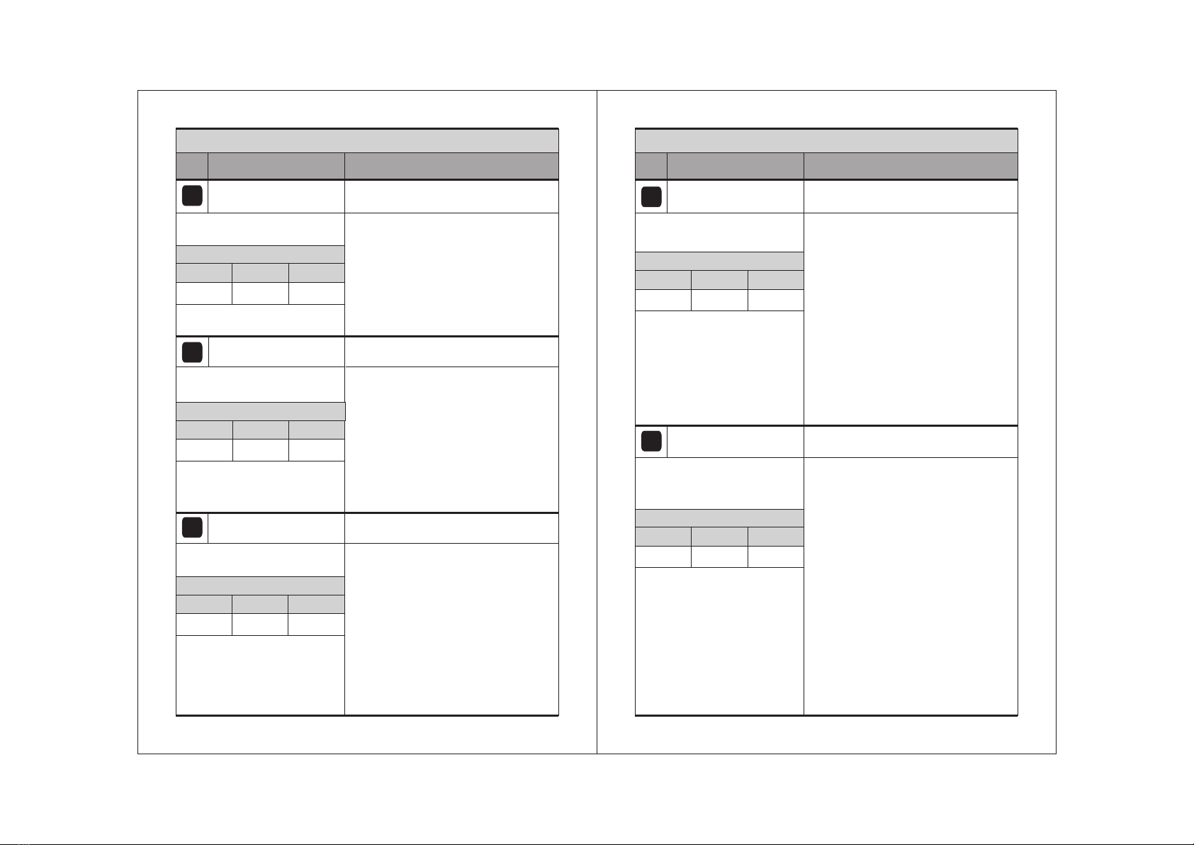
QUICK FREEZE SP
Use UP/DOWN keys to set desired value.
This Parameter will set QUICK Freeze Set
Point during QUICK Freezing Defrost will
not occur.
0
Example : If this set to -20 C, and quick
freeze frequency is set to 1 hr ,then when
it is set to quick freeze mode, then the
0
Comp. will take -20 C set point for 1 hr.
To change Quick Freeze SP
parameter, press the set key.
05
Function: To set Quick Freeze Set Point.
- 0ºC5 SP -20ºC
Range
Min Max Fact. Set
QUICK FREEZE DUR
Use UP/DOWN keys to set desired value.
This is the maximum amount of time
allowed for Quick Freeze. If set to “0”,
there will be no quick freeze.
Example : see QUICK FREEZE SP
parameter.
To change Quick Freeze Dur
parameter, press the set key.
06
Function: To set Quick Freeze Duration.
0Hrs 12 Hrs 0 Hrs
Range
Min Max Fact. Set
Use UP/DOWN keys to set desired value.
0
Example : If setpoint is set at 10 C and
0
differential is set at 2 C, then when the
0
system reaches 10 C, the compressor
relay will cutout and since the differential is
0
2 C, the relay will cutin (restart)
0 0 0
at 12 C (10 C + 2 C ).
04
DIFFERENTIAL Function: To set the differential for
compressor restart.
To change DIFFERENTIAL
parameter, press the set key.
1ºC 20ºC 2ºC
Range
Min Max Fact. Set
08
CRC1200
Sr.
No.
Parameter setting method
Description of parameters and functions.
Parameter
(LCD Message)
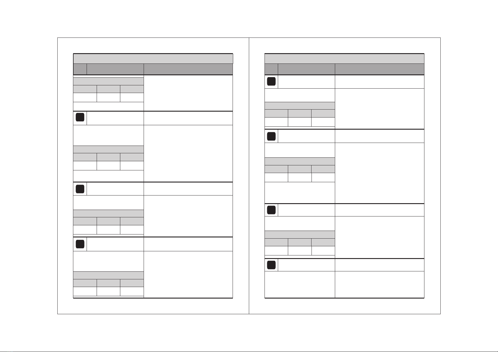
ROOM PROBE CAL
07
Function: To set room probe 1
calibration.
To change the Room Probe Cal
parameter, press the set key.
Use UP/DOWN keys to set desired value.
-10ºC 10ºC 0ºC
Range
Min Max Fact. Set
In time it may be possible that the display
may be offset by a degree or so. To
compensate for this error, you may need
to add or minus the degrees required to
achieve the correct temperature. Setting
o o
value is from -10 C to + 10 C.
Example : The temperature on the
o
display is 28 C, whereas the actual
o
temperature is 30 C. You will need to set
the Calib. Val to 2, which means that
once out of the programming mode, the
o
temperature will show 30 C
o o
(28 C + 2 C).
Use UP/DOWN keys to set desired value.
This parameter is used to protect the
compressor from restarting in a short
period of time and can be set between 0 to
20 minutes.
Example : If this parameter is set at 3
minutes, the relay will cut off at the set
temperature, but will not restart for a
minimum of 3 minutes, even if the
differential is achieved earlier. This
parameter is good to protect the life of the
compressor or even in applications where
the probe is placed at places where there
are sudden & short changes in
temperature .
COMP TIME DELAY
08
Function: To set time delay between
compressors relay restart time.
0 Min 20 Min 3 Min
To change the Comp Time
Delay parameter, press the set
key.
Range
Min Max Fact. Set


 User manual")