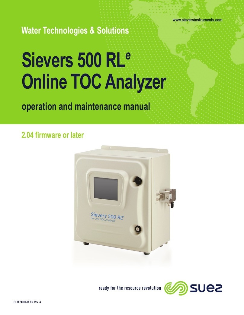
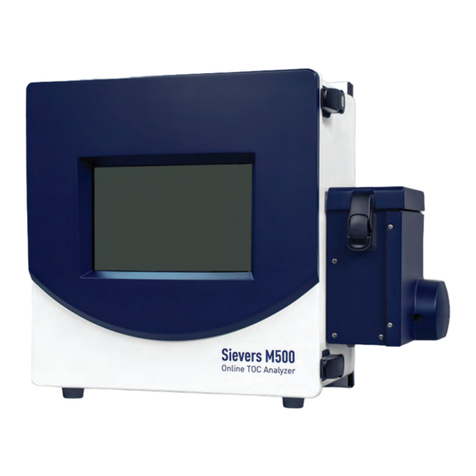
Suez Sievers M500e User manual

DLM 78510-02 EN REV B
Total Organic Carbon (TOC) Analyzer
Sievers M500e
1.05 firmware or later
Sievers M500e
operation and maintenance manual

Printed in the USA © 2022
6060 Spine Road
Boulder, CO 80301 USA
www.sieversinstruments.com
For technical support, contact Technical Support or your local service provider.
In the Americas, contact Technical Support at +1 888 245 2595.
In Europe, the Middle East, and Africa, contact
Technical Support at +44 161 864 6800.
To order standards or replacement parts, contact Customer Care
at +1 800 255 6964 or your local service provider.
For a copy of the Declaration of Conformity and ISO 9001 Registration:
Visit our website [Customer Support > Sievers Analyzers & Instruments >
Sievers Accreditations & Certificates > ISO Certifications and Accreditations
(or Declarations of Conformity)].
Electronic versions of the Analyzer’s Operation and Maintenance Manual
and the M500 Qualification Package — IQ/OQ Volume are available from our website: [Customer Support
> Sievers Analyzers & Instruments > Manuals and Validation Support Packages (VSPs) > M500].

IDENTIFICATION RECORDS
.............................
Sievers M500e TOC Analyzer Operation and Maintenance Manual
DLM 78510-02 EN Rev. B 3 SUEZ © 2022
IDENTIFICATION RECORDS
Analyzer serial number: _____________
(This is located on the side of the Analyzer.)
Date of receipt and installation of Analyzer: _____________
(This is the warranty start date.)
Default Administrative User ID: ADMIN
Default Administrative Password: SIEVERS

Sievers M500e TOC Analyzer Operation and Maintenance Manual
DLM 78510-02 EN Rev. B 4 SUEZ © 2022
Table of Contents
Identification Records . . . . . . . . . . . . . . . . . . . . . . . . . . . . . . . . . . . . . . . . . . . . . . . . 3
List of Tables. . . . . . . . . . . . . . . . . . . . . . . . . . . . . . . . . . . . . . . . . . . . . . 11
List of Figures . . . . . . . . . . . . . . . . . . . . . . . . . . . . . . . . . . . . . . . . . . . . . 12
Document Revision History . . . . . . . . . . . . . . . . . . . . . . . . . . . . . . . . . . . . . . . . . . 13
Trademarks and Patents . . . . . . . . . . . . . . . . . . . . . . . . . . . . . . . . . . . . . . . . . . . . 13
Confidentiality . . . . . . . . . . . . . . . . . . . . . . . . . . . . . . . . . . . . . . . . . . . . . . . . . . . . . 13
Declaration of Conformity . . . . . . . . . . . . . . . . . . . . . . . . . . . . . . . . . . . . . . . . . . . . 13
Standard Limited Warranty. . . . . . . . . . . . . . . . . . . . . . . . . . . . . . . . . . . . . . . . . . . 14
Warnings. . . . . . . . . . . . . . . . . . . . . . . . . . . . . . . . . . . . . . . . . . . . . . . . . . . . . . . . . 18
Chapter 1: Introduction . . . . . . . . . . . . . . . . . . . . . . . . . . . . . . . . . . . . . 52
Chapter 2: System Description . . . . . . . . . . . . . . . . . . . . . . . . . . . . . . . 53
System Specifications. . . . . . . . . . . . . . . . . . . . . . . . . . . . . . . . . . . . . . . . . . . . . . . 53
System Overview . . . . . . . . . . . . . . . . . . . . . . . . . . . . . . . . . . . . . . . . . . . . . . . .54
Sample Flow Path. . . . . . . . . . . . . . . . . . . . . . . . . . . . . . . . . . . . . . . . . . . . . . . . . . 55
Additional System Components . . . . . . . . . . . . . . . . . . . . . . . . . . . . . . . . . . . . . . . 57
Microprocessor Controller and Electronics . . . . . . . . . . . . . . . . . . . . . . . . . . . . .57
Data Outputs . . . . . . . . . . . . . . . . . . . . . . . . . . . . . . . . . . . . . . . . . . . . . . . . . . .57
Chapter 3: Installation . . . . . . . . . . . . . . . . . . . . . . . . . . . . . . . . . . . . . . 58
Overview. . . . . . . . . . . . . . . . . . . . . . . . . . . . . . . . . . . . . . . . . . . . . . . . . . . . . . . . . 58
Step 1: Unpack and Inspect the Analyzer . . . . . . . . . . . . . . . . . . . . . . . . 59
Packing List . . . . . . . . . . . . . . . . . . . . . . . . . . . . . . . . . . . . . . . . . . . . . . . . . . . .60
Additional Installation Equipment . . . . . . . . . . . . . . . . . . . . . . . . . . . . . . . . . . . .61
Step 2: Complete the Identification Records . . . . . . . . . . . . . . . . . . . . . 62
Step 3: Select a Location for the Analyzer . . . . . . . . . . . . . . . . . . . . . . . 62
Step 4: Install I/O Control Wiring (Optional) . . . . . . . . . . . . . . . . . . . . . . 63
Installing I/O Wiring . . . . . . . . . . . . . . . . . . . . . . . . . . . . . . . . . . . . . . . . . . . . . .63

Sievers M500e TOC Analyzer Operation and Maintenance Manual
DLM 78510-02 EN Rev. B 5 SUEZ © 2022
Working with Alarm Outputs (J1) . . . . . . . . . . . . . . . . . . . . . . . . . . . . . . . . . . . .68
Working with 4-20 mA Analog (J4) Outputs . . . . . . . . . . . . . . . . . . . . . . . . . . . .69
Working with Binary Inputs (Remote Start/Stop) (J2) . . . . . . . . . . . . . . . . . . . . .71
Step 5: Install Power . . . . . . . . . . . . . . . . . . . . . . . . . . . . . . . . . . . . . . . . . 73
Installing the AC Conduit . . . . . . . . . . . . . . . . . . . . . . . . . . . . . . . . . . . . . . . . . .73
Step 6: Connect the Sample Inlet and Outlet Ports . . . . . . . . . . . . . . . . 77
Configuring the Sample Inlet and Outlet Ports . . . . . . . . . . . . . . . . . . . . . . . . . .77
Step 7: Install the DI Water System . . . . . . . . . . . . . . . . . . . . . . . . . . . . . 78
Using the Instrument Startup Wizard . . . . . . . . . . . . . . . . . . . . . . . . . . . . . . . . .78
Step 8: Install Ethernet and External Devices . . . . . . . . . . . . . . . . . . . . 87
Installing a USB Connection for Data Transfer (Optional) . . . . . . . . . . . . . . . . .88
Installing a Serial Connection (Optional) . . . . . . . . . . . . . . . . . . . . . . . . . . . . . .88
Installing an Ethernet Connection (Optional) . . . . . . . . . . . . . . . . . . . . . . . . . . .89
Step 9: Configure Basic Analyzer Settings. . . . . . . . . . . . . . . . . . . . . . . 90
Enabling Analyzer Security (Optional) . . . . . . . . . . . . . . . . . . . . . . . . . . . . . . . .90
Enabling Password Protection (Optional) . . . . . . . . . . . . . . . . . . . . . . . . . . . . . .90
Configuring Local Settings . . . . . . . . . . . . . . . . . . . . . . . . . . . . . . . . . . . . . . . . .92
Setting the Measurement Mode . . . . . . . . . . . . . . . . . . . . . . . . . . . . . . . . . . . . .94
Configuring an Ethernet Connection . . . . . . . . . . . . . . . . . . . . . . . . . . . . . . . . .98
Enabling a PDF Printer . . . . . . . . . . . . . . . . . . . . . . . . . . . . . . . . . . . . . . . . . . .100
Setting up a Wireless Connection . . . . . . . . . . . . . . . . . . . . . . . . . . . . . . . . . .102
Saving System Constants . . . . . . . . . . . . . . . . . . . . . . . . . . . . . . . . . . . . . . . .104
Configuring the Data I/O . . . . . . . . . . . . . . . . . . . . . . . . . . . . . . . . . . . . . . . . . .106
Chapter 4: Basic Analyzer Operation . . . . . . . . . . . . . . . . . . . . . . . . . 111
Overview. . . . . . . . . . . . . . . . . . . . . . . . . . . . . . . . . . . . . . . . . . . . . . . . . . . . . . . . 111
Powering On and Off the Analyzer . . . . . . . . . . . . . . . . . . . . . . . . . . . . . . . . . .111
Recommended Operational State . . . . . . . . . . . . . . . . . . . . . . . . . . . . . . . . . . . . . 114
The iOS System . . . . . . . . . . . . . . . . . . . . . . . . . . . . . . . . . . . . . . . . . . . . . . . . . . 114
Using the Standard iOS System . . . . . . . . . . . . . . . . . . . . . . . . . . . . . . . . . . . .115
Using the Sample Inlet Block . . . . . . . . . . . . . . . . . . . . . . . . . . . . . . . . . . . . . .115

Sievers M500e TOC Analyzer Operation and Maintenance Manual
DLM 78510-02 EN Rev. B 6 SUEZ © 2022
Steam Exposure . . . . . . . . . . . . . . . . . . . . . . . . . . . . . . . . . . . . . . . . . . . . . . . . . . 116
The Analyzer Screens . . . . . . . . . . . . . . . . . . . . . . . . . . . . . . . . . . . . . . . . . . . . . 117
Navigating the Analyzer Screens . . . . . . . . . . . . . . . . . . . . . . . . . . . . . . . . . . .117
The Standard Toolbar . . . . . . . . . . . . . . . . . . . . . . . . . . . . . . . . . . . . . . . . . . . . . . 117
Printing and Exporting from the Analyzer Screens . . . . . . . . . . . . . . . . . . . . . .120
The Home Screen. . . . . . . . . . . . . . . . . . . . . . . . . . . . . . . . . . . . . . . . . . . . . . . . . 122
Setting the Measurement Mode . . . . . . . . . . . . . . . . . . . . . . . . . . . . . . . . . . . .124
Running Online Analysis . . . . . . . . . . . . . . . . . . . . . . . . . . . . . . . . . . . . . . . . .127
Running a Grab Sample . . . . . . . . . . . . . . . . . . . . . . . . . . . . . . . . . . . . . . . . . .128
The Protocols Screen . . . . . . . . . . . . . . . . . . . . . . . . . . . . . . . . . . . . . . . . . . . . . . 130
Protocols Screen — Online Data Tab . . . . . . . . . . . . . . . . . . . . . . . . . . . . . . .130
Protocols Screen — System Protocols and Grab Methods Data Tab . . . . . . . . . 132
The Settings Screen . . . . . . . . . . . . . . . . . . . . . . . . . . . . . . . . . . . . . . . . . . . . . . . 133
Settings Screen — System Setup Tab . . . . . . . . . . . . . . . . . . . . . . . . . . . . . . . . . 133
Configuring Local Settings . . . . . . . . . . . . . . . . . . . . . . . . . . . . . . . . . . . . . . . .133
Configuring Result Preferences . . . . . . . . . . . . . . . . . . . . . . . . . . . . . . . . . . . .136
Setting Trend Graph Display Options . . . . . . . . . . . . . . . . . . . . . . . . . . . . . . . .137
Configuring Export Preferences . . . . . . . . . . . . . . . . . . . . . . . . . . . . . . . . . . . .138
Settings Screen — Instrument Settings Tab. . . . . . . . . . . . . . . . . . . . . . . . . . . . . 140
Viewing System Constants . . . . . . . . . . . . . . . . . . . . . . . . . . . . . . . . . . . . . . . .140
Saving System Constants . . . . . . . . . . . . . . . . . . . . . . . . . . . . . . . . . . . . . . . .140
Printing and Exporting or System Constants . . . . . . . . . . . . . . . . . . . . . . . . . .140
Importing System Constants . . . . . . . . . . . . . . . . . . . . . . . . . . . . . . . . . . . . . .142
Settings Screen — Analyzer Settings Panel. . . . . . . . . . . . . . . . . . . . . . . . . . . . . 143
Reviewing Analyzer Settings . . . . . . . . . . . . . . . . . . . . . . . . . . . . . . . . . . . . . .143
Saving Analyzer Settings . . . . . . . . . . . . . . . . . . . . . . . . . . . . . . . . . . . . . . . . .144
Importing Analyzer Settings . . . . . . . . . . . . . . . . . . . . . . . . . . . . . . . . . . . . . . .145
Setting a User TOC Offset . . . . . . . . . . . . . . . . . . . . . . . . . . . . . . . . . . . . . . . .146
Activating Options . . . . . . . . . . . . . . . . . . . . . . . . . . . . . . . . . . . . . . . . . . . . . .147
Upgrading Firmware . . . . . . . . . . . . . . . . . . . . . . . . . . . . . . . . . . . . . . . . . . . . .148
Settings Screen — Hardware Tab . . . . . . . . . . . . . . . . . . . . . . . . . . . . . . . . . . . . 151
Configuring Alarm Outputs . . . . . . . . . . . . . . . . . . . . . . . . . . . . . . . . . . . . . . . .152

Sievers M500e TOC Analyzer Operation and Maintenance Manual
DLM 78510-02 EN Rev. B 7 SUEZ © 2022
Configuring 4-20 mA Analog Outputs . . . . . . . . . . . . . . . . . . . . . . . . . . . . . . . .154
Configuring Binary Input (Start/Stop) . . . . . . . . . . . . . . . . . . . . . . . . . . . . . . . .155
Configuring an Ethernet Connection . . . . . . . . . . . . . . . . . . . . . . . . . . . . . . . .157
Configuring the Flow Sensor . . . . . . . . . . . . . . . . . . . . . . . . . . . . . . . . . . . . . .158
Enabling the DI Reservoir Level Sensor . . . . . . . . . . . . . . . . . . . . . . . . . . . . .160
Enabling the UV Lamp . . . . . . . . . . . . . . . . . . . . . . . . . . . . . . . . . . . . . . . . . . .161
Enabling a PDF Printer . . . . . . . . . . . . . . . . . . . . . . . . . . . . . . . . . . . . . . . . . . .162
Configuring a WiFi Connection (Optional) . . . . . . . . . . . . . . . . . . . . . . . . . . . .164
Settings Screen — Consumables Tab . . . . . . . . . . . . . . . . . . . . . . . . . . . . . . . . . 165
Entering and Reviewing Consumables Status . . . . . . . . . . . . . . . . . . . . . . . . .165
Settings Screen — Errors Tab . . . . . . . . . . . . . . . . . . . . . . . . . . . . . . . . . . . . . . . 166
Settings Screen — Backup/Restore Tab . . . . . . . . . . . . . . . . . . . . . . . . . . . . . . . 167
Backing Up the Database . . . . . . . . . . . . . . . . . . . . . . . . . . . . . . . . . . . . . . . . .167
Scheduling Automatic Database Backups . . . . . . . . . . . . . . . . . . . . . . . . . . . .169
Archiving the Database . . . . . . . . . . . . . . . . . . . . . . . . . . . . . . . . . . . . . . . . . .171
Restoring a Backup . . . . . . . . . . . . . . . . . . . . . . . . . . . . . . . . . . . . . . . . . . . . .175
Restoring System Constants . . . . . . . . . . . . . . . . . . . . . . . . . . . . . . . . . . . . . .176
The Data Screen. . . . . . . . . . . . . . . . . . . . . . . . . . . . . . . . . . . . . . . . . . . . . . . . . . 177
Reviewing Data History . . . . . . . . . . . . . . . . . . . . . . . . . . . . . . . . . . . . . . . . . .177
The Password Protection Screen . . . . . . . . . . . . . . . . . . . . . . . . . . . . . . . . . . . . . 182
The Help Screen. . . . . . . . . . . . . . . . . . . . . . . . . . . . . . . . . . . . . . . . . . . . . . . . . . 182
Chapter 5: Password Protection . . . . . . . . . . . . . . . . . . . . . . . . . . . . . 183
Overview. . . . . . . . . . . . . . . . . . . . . . . . . . . . . . . . . . . . . . . . . . . . . . . . . . . . . . . . 183
Password Protection. . . . . . . . . . . . . . . . . . . . . . . . . . . . . . . . . . . . . . . . . . . . . . . 183
Using Password Protection . . . . . . . . . . . . . . . . . . . . . . . . . . . . . . . . . . . . . . .183
Enabling Password Protection . . . . . . . . . . . . . . . . . . . . . . . . . . . . . . . . . . . . .183
Chapter 6: Calibration and System Protocols . . . . . . . . . . . . . . . . . . 186
Overview . . . . . . . . . . . . . . . . . . . . . . . . . . . . . . . . . . . . . . . . . . . . . . . . . . . . . . . .186
Programming the TOC Autozero . . . . . . . . . . . . . . . . . . . . . . . . . . . . . . . . . . . . . .187
To program the TOC Autozero . . . . . . . . . . . . . . . . . . . . . . . . . . . . . . . . . . . . . . . . . . 187
Programming the TC/IC Conductivity Autozero . . . . . . . . . . . . . . . . . . . . . . . . . . .189
Required Calibration Supplies . . . . . . . . . . . . . . . . . . . . . . . . . . . . . . . . . . . . . . . .190

Sievers M500e TOC Analyzer Operation and Maintenance Manual
DLM 78510-02 EN Rev. B 8 SUEZ © 2022
Calibration Preparations . . . . . . . . . . . . . . . . . . . . . . . . . . . . . . . . . . . . . . . . . . . .192
Saving System Settings . . . . . . . . . . . . . . . . . . . . . . . . . . . . . . . . . . . . . . . . . . . . . . . 192
Performing Annual Maintenance Tasks . . . . . . . . . . . . . . . . . . . . . . . . . . . . . . . . . . . 196
Handling Standards . . . . . . . . . . . . . . . . . . . . . . . . . . . . . . . . . . . . . . . . . . . . . . . . . . . 196
Disable Automatic Backup . . . . . . . . . . . . . . . . . . . . . . . . . . . . . . . . . . . . . . . . . . . . . 197
Protocol and Calibration Instructions . . . . . . . . . . . . . . . . . . . . . . . . . . . . . . . .198
4-20 mA Output Operation Verification Protocol (Optional) . . . . . . . . . . . . . . . . . . . . 199
TOC Single Point Calibration Protocol . . . . . . . . . . . . . . . . . . . . . . . . . . . . . . . . . . . . 204
Low Level TOC Single Point Calibration Protocol . . . . . . . . . . . . . . . . . . . . . . . . . . . . 208
TOC Multi-point Calibration Protocol . . . . . . . . . . . . . . . . . . . . . . . . . . . . . . . . . . . . . . 212
TC/IC Conductivity Autozero Protocol . . . . . . . . . . . . . . . . . . . . . . . . . . . . . . . . . . . . . 217
TOC Autozero Calibration Protocol . . . . . . . . . . . . . . . . . . . . . . . . . . . . . . . . . . . . . . . 220
Accuracy & Precision Verification Protocol . . . . . . . . . . . . . . . . . . . . . . . . . . . . . . . . . 223
Low Level Accuracy & Precision Verification Protocol . . . . . . . . . . . . . . . . . . . . . . . . 226
Reviewing Calibration and Verification History . . . . . . . . . . . . . . . . . . . . . . . . . . .229
Protocol and Calibration Worksheets . . . . . . . . . . . . . . . . . . . . . . . . . . . . . . . .231
4-20 mA Output Operation Verification (Optional) Worksheet . . . . . . . . . . . . . . . . . . 232
TOC Single Point Calibration Worksheet . . . . . . . . . . . . . . . . . . . . . . . . . . . . . . . . . . 233
Low Level TOC Single Point Calibration Worksheet . . . . . . . . . . . . . . . . . . . . . . . . . . 234
TOC Multi-Point Calibration Worksheet . . . . . . . . . . . . . . . . . . . . . . . . . . . . . . . . . . . 235
TC/IC Conductivity Autozero Worksheet . . . . . . . . . . . . . . . . . . . . . . . . . . . . . . . . . . . 236
TOC Autozero Worksheet . . . . . . . . . . . . . . . . . . . . . . . . . . . . . . . . . . . . . . . . . . . . . . 237
Accuracy & Precision Verification Worksheet . . . . . . . . . . . . . . . . . . . . . . . . . . . . . . . 238
Low Level Accuracy & Precision Verification Worksheet . . . . . . . . . . . . . . . . . . . . . . 239
Chapter 7: Troubleshooting . . . . . . . . . . . . . . . . . . . . . . . . . . . . . . . . . 240
Overview. . . . . . . . . . . . . . . . . . . . . . . . . . . . . . . . . . . . . . . . . . . . . . . . . . . . . . . . 240
Step 1: Visual Inspection . . . . . . . . . . . . . . . . . . . . . . . . . . . . . . . . . . . . 240
Inspecting Externally . . . . . . . . . . . . . . . . . . . . . . . . . . . . . . . . . . . . . . . . . . . .240
Inspecting Internally . . . . . . . . . . . . . . . . . . . . . . . . . . . . . . . . . . . . . . . . . . . . .241
Step 2: Review Warnings and Errors. . . . . . . . . . . . . . . . . . . . . . . . . . . 243
Reviewing Errors and Warnings . . . . . . . . . . . . . . . . . . . . . . . . . . . . . . . . . . . .243
Warnings and Error Messages . . . . . . . . . . . . . . . . . . . . . . . . . . . . . . . . . . . . .246
3100—Unexpected DI Loop level . . . . . . . . . . . . . . . . . . . . . . . . . . . . . . . . . . . . . 246
3102—DI flow on IC/TC channel not detected . . . . . . . . . . . . . . . . . . . . . . . . . . . 246
Step 3: Review Solutions for Basic Problems . . . . . . . . . . . . . . . . . . . 247

Sievers M500e TOC Analyzer Operation and Maintenance Manual
DLM 78510-02 EN Rev. B 9 SUEZ © 2022
The Analyzer Will Not Power On . . . . . . . . . . . . . . . . . . . . . . . . . . . . . . . . . . . . . . 247
Checking the Sample Pump . . . . . . . . . . . . . . . . . . . . . . . . . . . . . . . . . . . . . . . . . 247
No Sample Flow Through the Analyzer . . . . . . . . . . . . . . . . . . . . . . . . . . . . . . . . . 248
Confirm Flow of Water through the Measurement Module, DI Side . . . . . . . . . . . 249
Additional Troubleshooting Steps . . . . . . . . . . . . . . . . . . . . . . . . . . . . . . . . . . .250
TC/IC Conductivity Autozero . . . . . . . . . . . . . . . . . . . . . . . . . . . . . . . . . . . . . . . . . 250
TOC Autozero . . . . . . . . . . . . . . . . . . . . . . . . . . . . . . . . . . . . . . . . . . . . . . . . . . . . 250
TOC Offset . . . . . . . . . . . . . . . . . . . . . . . . . . . . . . . . . . . . . . . . . . . . . . . . . . . . . . 250
Problems Changing the Program Language . . . . . . . . . . . . . . . . . . . . . . . . . . . . 251
Problems with The DI Water Pump . . . . . . . . . . . . . . . . . . . . . . . . . . . . . . . . . . . . 253
Using the Diagnostics Menu . . . . . . . . . . . . . . . . . . . . . . . . . . . . . . . . . . . . . . .253
System Tests . . . . . . . . . . . . . . . . . . . . . . . . . . . . . . . . . . . . . . . . . . . . . . . . . . . . 255
Alarms . . . . . . . . . . . . . . . . . . . . . . . . . . . . . . . . . . . . . . . . . . . . . . . . . . . . . . .255
Analog Outputs . . . . . . . . . . . . . . . . . . . . . . . . . . . . . . . . . . . . . . . . . . . . . . . .257
Modbus . . . . . . . . . . . . . . . . . . . . . . . . . . . . . . . . . . . . . . . . . . . . . . . . . . . . . .258
Network Folder . . . . . . . . . . . . . . . . . . . . . . . . . . . . . . . . . . . . . . . . . . . . . . . . .259
Printer . . . . . . . . . . . . . . . . . . . . . . . . . . . . . . . . . . . . . . . . . . . . . . . . . . . . . . . .260
Sample Flow Rate . . . . . . . . . . . . . . . . . . . . . . . . . . . . . . . . . . . . . . . . . . . . . .260
IC Power Relay . . . . . . . . . . . . . . . . . . . . . . . . . . . . . . . . . . . . . . . . . . . . . . . .261
Internet Connection . . . . . . . . . . . . . . . . . . . . . . . . . . . . . . . . . . . . . . . . . . . . .261
USB Serial Loopback . . . . . . . . . . . . . . . . . . . . . . . . . . . . . . . . . . . . . . . . . . . .262
Serial Loopback . . . . . . . . . . . . . . . . . . . . . . . . . . . . . . . . . . . . . . . . . . . . . . . .263
WiFi . . . . . . . . . . . . . . . . . . . . . . . . . . . . . . . . . . . . . . . . . . . . . . . . . . . . . . . . .263
Export Diagnostics . . . . . . . . . . . . . . . . . . . . . . . . . . . . . . . . . . . . . . . . . . . . . .264
Service Diagnostics . . . . . . . . . . . . . . . . . . . . . . . . . . . . . . . . . . . . . . . . . . . . . . . 265
Level 1 Diagnostics. . . . . . . . . . . . . . . . . . . . . . . . . . . . . . . . . . . . . . . . . . . . . . . . 266
Step 4: Contact Technical Support . . . . . . . . . . . . . . . . . . . . . . . . . . . . 266
Step 5: Return the Analyzer to SUEZ. . . . . . . . . . . . . . . . . . . . . . . . . . . 267
To prepare Analyzer for shipping . . . . . . . . . . . . . . . . . . . . . . . . . . . . . . . . . . .267
Draining the Sample Side . . . . . . . . . . . . . . . . . . . . . . . . . . . . . . . . . . . . . . . . . . . 267
Draining the DI Loop . . . . . . . . . . . . . . . . . . . . . . . . . . . . . . . . . . . . . . . . . . . . . . . 271
Chapter 8: Maintenance . . . . . . . . . . . . . . . . . . . . . . . . . . . . . . . . . . . . 274
Replacing Consumables and Maintenance Items . . . . . . . . . . . . . . . . . . . . . .274
Verifying the DI Water Level . . . . . . . . . . . . . . . . . . . . . . . . . . . . . . . . . . . . . . .276

Sievers M500e TOC Analyzer Operation and Maintenance Manual
DLM 78510-02 EN Rev. B 10 SUEZ © 2022
Replacing the UV Lamp . . . . . . . . . . . . . . . . . . . . . . . . . . . . . . . . . . . . . . . . . .278
Replacing the Sample Pump Heads . . . . . . . . . . . . . . . . . . . . . . . . . . . . . . . .280
Replacing the Resin Cartridge . . . . . . . . . . . . . . . . . . . . . . . . . . . . . . . . . . . . .282
Replacing the In-Line Filter Element . . . . . . . . . . . . . . . . . . . . . . . . . . . . . . . .285
Replacing the Fan Filter . . . . . . . . . . . . . . . . . . . . . . . . . . . . . . . . . . . . . . . . . .286
Entering New Consumables Installation Dates . . . . . . . . . . . . . . . . . . . . . . . .287
Cleaning the Analyzer . . . . . . . . . . . . . . . . . . . . . . . . . . . . . . . . . . . . . . . . . . .288
Appendix A: Analyzer Dimensions . . . . . . . . . . . . . . . . . . . . . . . . . . . 290
Analyzer Dimensions . . . . . . . . . . . . . . . . . . . . . . . . . . . . . . . . . . . . . . . . . . . . . . 290
Analyzer Configured with Standard iOS . . . . . . . . . . . . . . . . . . . . . . . . . . . . . .291
Analyzer Configured with Sample Inlet Block . . . . . . . . . . . . . . . . . . . . . . . . . .294
Appendix B: Streaming Data . . . . . . . . . . . . . . . . . . . . . . . . . . . . . . . . 297
Data-Streaming Methods . . . . . . . . . . . . . . . . . . . . . . . . . . . . . . . . . . . . . . . . .297
To stream data via a serial (RS-232) port . . . . . . . . . . . . . . . . . . . . . . . . . . . . . . . 297
To stream data via Ethernet . . . . . . . . . . . . . . . . . . . . . . . . . . . . . . . . . . . . . . . . . 298
Determining Your Communications Port Number . . . . . . . . . . . . . . . . . . . . . .299
Appendix C: Warning and Error Descriptions . . . . . . . . . . . . . . . . . . 300
Appendix D: DI Water Installation Details. . . . . . . . . . . . . . . . . . . . . . 308
Additional DI Water Installation Details. . . . . . . . . . . . . . . . . . . . . . . . . . . . . . . . . 308
Installing the resin cartridge . . . . . . . . . . . . . . . . . . . . . . . . . . . . . . . . . . . . . . .308
Rinsing the Analyzer . . . . . . . . . . . . . . . . . . . . . . . . . . . . . . . . . . . . . . . . . . . .313
Appendix E: Modbus with the Analyzer . . . . . . . . . . . . . . . . . . . . . . . 315
The Ethernet Connection and Modbus. . . . . . . . . . . . . . . . . . . . . . . . . . . . . . . . . 315
Enabling Modbus . . . . . . . . . . . . . . . . . . . . . . . . . . . . . . . . . . . . . . . . . . . . . . .315
Testing Modbus for the Analyzer . . . . . . . . . . . . . . . . . . . . . . . . . . . . . . . . . . .316
The Modbus Register Table . . . . . . . . . . . . . . . . . . . . . . . . . . . . . . . . . . . . . . . . . 316
Index. . . . . . . . . . . . . . . . . . . . . . . . . . . . . . . . . . . . . . . . . . . . . . . . . . . . 322

Sievers M500e TOC Analyzer Operation and Maintenance Manual
DLM 78510-02 EN Rev. B 11 SUEZ © 2022
List of Tables
Table 3-1 Alarm Relay Outputs (J1) . . . . . . . . . . . . . . . . . . . . . . . . . . . . . . . . . . . . . . 69
Table 3-2 4-20 mA Analog Outputs (J4) . . . . . . . . . . . . . . . . . . . . . . . . . . . . . . . . . . . 70
Table 3-3 Isolated State Inputs (J2) . . . . . . . . . . . . . . . . . . . . . . . . . . . . . . . . . . . . . . 72
Table 3-4 I/O Panel 9-Pin Male D Connector . . . . . . . . . . . . . . . . . . . . . . . . . . . . . . . 89
Table 4-1 The Analyzer’s Standard Toolbar . . . . . . . . . . . . . . . . . . . . . . . . . . . . . . . 119
Table 6-1 Standards Required for TOC Single-Point Calibration . . . . . . . . . . . . . . . 192
Table 6-2 Standards Required for TOC Multi-Point Calibration . . . . . . . . . . . . . . . . 192
Table 6-3 Standards Required for Accuracy & Precision Verification. . . . . . . . . . . . 192
Table 8-1 Replacement Schedule for Consumables . . . . . . . . . . . . . . . . . . . . . . . . 272
Table 8-2 Sievers M500e TOC Analyzer 3-Year Maintenance Worksheet. . . . . . . . 285
Table E-1 Modbus Register Table. . . . . . . . . . . . . . . . . . . . . . . . . . . . . . . . . . . . . . . 315

Sievers M500e TOC Analyzer Operation and Maintenance Manual
DLM 78510-02 EN Rev. B 12 SUEZ © 2022
List of Figures
Figure 2-1 Analyzer Schematic (Shown with Standard iOS). . . . . . . . . . . . . . . . . . . . 56
Figure 3-1 Interior Overview of the Analyzer. . . . . . . . . . . . . . . . . . . . . . . . . . . . . . . . 60
Figure 3-2 Alarm Relay Output Detail . . . . . . . . . . . . . . . . . . . . . . . . . . . . . . . . . . . . . 69
Figure 3-3 Typical 4-20 mA Circuit Applications . . . . . . . . . . . . . . . . . . . . . . . . . . . . . 71
Figure 3-4 Isolated State Input Circuit Detail . . . . . . . . . . . . . . . . . . . . . . . . . . . . . . . 72
Figure 3-5 Instrument-Powered Isolated State Input Circuit Application. . . . . . . . . . . 73
Figure 3-6 Externally-Powered Isolated State Input Circuit Application . . . . . . . . . . . 73
Figure 3-7 Input and Output Connections . . . . . . . . . . . . . . . . . . . . . . . . . . . . . . . . . . 88
Figure 3-8 Asynchronous Serial Port (RS-232). . . . . . . . . . . . . . . . . . . . . . . . . . . . . . 90
Figure 3-9 Measurement Mode shown in Protocol field . . . . . . . . . . . . . . . . . . . . . . . 98
Figure 4-1 Home screen when Password Protection is not enabled . . . . . . . . . . . . 113
Figure 4-2 Home screen when Password Protection is enabled . . . . . . . . . . . . . . . 114
Figure 4-3 The Standard iOS System. . . . . . . . . . . . . . . . . . . . . . . . . . . . . . . . . . . . 116
Figure 4-4 The Sample Inlet Block . . . . . . . . . . . . . . . . . . . . . . . . . . . . . . . . . . . . . . 116
Figure 4-5 Standard Toolbar. . . . . . . . . . . . . . . . . . . . . . . . . . . . . . . . . . . . . . . . . . . 119
Figure 4-6 The Home Screen . . . . . . . . . . . . . . . . . . . . . . . . . . . . . . . . . . . . . . . . . . 123
Figure 4-7 Online Data Graphical View. . . . . . . . . . . . . . . . . . . . . . . . . . . . . . . . . . . 131
Figure 4-8 Online Data Table View. . . . . . . . . . . . . . . . . . . . . . . . . . . . . . . . . . . . . . 132
Figure 4-9 Online Data Details . . . . . . . . . . . . . . . . . . . . . . . . . . . . . . . . . . . . . . . . . 132
Figure 4-10 System Protocols and Grab Methods Data Tab . . . . . . . . . . . . . . . . . . 133
Figure 8-1 Interior Overview of the Analyzer. . . . . . . . . . . . . . . . . . . . . . . . . . . . . . . 272
Figure A-1 Analyzer Dimensions, with Standard iOS System. . . . . . . . . . . . . . . . . . 288
Figure A-2 Right-Side Analyzer Dimensions, with Standard iOS System. . . . . . . . . 289
Figure A-3 Left-Side Analyzer Dimensions, with Standard iOS System . . . . . . . . . . 290
Figure A-4 Analyzer Dimensions, with Sample Inlet Block . . . . . . . . . . . . . . . . . . . . 291
Figure A-5 Right-Side Analyzer Dimensions, with Sample Inlet Block . . . . . . . . . . . 292
Figure A-6 Left-Side Analyzer Dimensions with Sample Inlet Block. . . . . . . . . . . . . 293

Sievers M500e TOC Analyzer Operation and Maintenance Manual
DLM 78510-02 EN Rev. B 13 SUEZ © 2022
DOCUMENT REVISION HISTORY
Document Version Firmware Version/Enhancement Date
DLM 78510-01 EN Rev. A 1.00 December 2020
DLM 78510-02 EN Rev. A 1.05 March 2022
DLM 78510-02 EN Rev. B 1.05 July 2022
TRADEMARKS AND PATENTS
Sievers,® DataGuard,® and Super iOS® are trademarks of SUEZ and may be registered
in one or more countries.
Centronics® is a trademark of Centronics Data Computer Corporation; Citizen® is a
registered trademark of CBM, Inc; Epson® is a registered trademark of Seiko Epson,
Inc.; IBM® is a registered trademark of International Business Machines Corporation;
John Guest® is a registered trademark of John Guest International Limited; Swagelok®
is a registered trademark of the Swagelok Company; Teflon® is a registered trademark
of E.I. du Pont de Nemours. Windows® and Excel® are registered trademarks of the
Microsoft Corporation.
The Analyzer described in this manual is covered by one or more patents issued to and
owned or pending by SUEZ, including the following:
US 6723565 and any of its non-US counterparts
US 8101417 and any of its non-US counterparts
US 8003048 and any of its non-US counterparts
US 9116099 and any of its non-US counterparts
US 9074967 and any of its non-US counterparts
and other patents pending
CONFIDENTIALITY
The information contained in this manual may be confidential and proprietary and is the
property of SUEZ. Information disclosed herein shall not be used to manufacture,
construct, or otherwise reproduce the goods disclosed herein. The information disclosed
herein shall not be disclosed to others or made public in any manner without the express
written consent of SUEZ.
DECLARATION OF CONFORMITY
A copy of the Declaration of Conformity for this product is available on our website.

Sievers M500e TOC Analyzer Operation and Maintenance Manual
DLM 78510-02 EN Rev. B 14 SUEZ © 2022
STANDARD LIMITED WARRANTY
SUEZ warrants its Sievers® products for defects in materials and workmanship. SUEZ will, at its
option, repair or replace instrument components that prove to be defective with new or re-
manufactured components. The warranty set forth is exclusive and no other warranty, whether written
or oral, is expressed or implied.
WARRANTY TERM
The SUEZ warranty term is thirteen (13) months ex-works, or twelve (12) months from
installation or start up by SUEZ certified service personnel. In no event shall the standard
limited warranty coverage extend beyond thirteen (13) months from original shipment date.
WARRANTY SERVICE
Warranty Service is provided to customers through telephone support, Monday - Friday, from
8:00 a.m. to 5:00 p.m. (Mountain Time), excluding all company and legal holidays. Telephone
support is provided for troubleshooting and determination of parts to be shipped from SUEZ
to the customer in order to return the product to operation. If telephone support is not
effective, the product may be returned to SUEZ for repair or replacement. In some instances,
suitable instruments may be available for short duration loan or lease.
SUEZ warrants that any labor services provided shall conform to the reasonable standards of
technical competency and performance effective at the time of delivery. All service
interventions are to be reviewed and authorized as correct and complete at the completion of
the service by a customer representative, or designate. SUEZ warrants these services for 30
days after the authorization and will correct any qualifying deficiency in labor provided that
the labor service deficiency is exactly related to the originating event. No other remedy, other
than the provision of labor services, may be applicable.
Repair components (parts and materials), but not consumables, provided in the course of a
repair, or purchased individually, are warranted for 90 days ex-works for materials and
workmanship. In no event will the incorporation of a warranted repair component into an
instrument extend the whole instrument’s warranty beyond its original term.
Consumables (e.g., dilution standards, verification solutions, and UV lamps, etc.) are
warranted to the extent of their stated shelf life, provided these items are maintained within
the stated environmental limitations. Warranty claims for consumables and verification
standards are limited to the replacement of the defective items, prorated from the time of
claim to the expiration of shelf life.
SHIPPING
A Repair Authorization Number (RA) must be obtained from the Technical Support Group
before any product can be returned to the factory. SUEZ will pay freight charges, exclusive of
any taxes and duties, for replacement or repaired products shipped to the customer site.
Customers shall pay freight charges, including all taxes and duties, for all products returning
to SUEZ. Any product returned to the factory without an RA number will be returned to the
customer.

Sievers M500e TOC Analyzer Operation and Maintenance Manual
DLM 78510-02 EN Rev. B 15 SUEZ © 2022
LIMITATION OF REMEDIES AND LIABILITY
The foregoing warranty shall not apply to defects resulting from improper or inadequate
installation, maintenance, adjustment, calibration, or operation by customer. Installation,
maintenance, adjustment, calibration, or operation must be performed in accordance with
instructions stated in the Operation and Maintenance Manual. Usage of non-recommended
maintenance materials may void a warranty claim.
The remedies provided herein are the customer's sole and exclusive remedies. In no event
shall SUEZ be liable for direct, indirect, special, incidental or consequential damages
(including loss of profits) whether based on contract, tort, or any other legal theory. The
Operation and Maintenance Manual is believed to be accurate at the time of publication and
no responsibility is taken for any errors that may be present. In no event shall SUEZ be liable
for incidental or consequential damages in connection with or arising from the use of the
manual and its accompanying related materials. Warranty is valid only for the original
purchaser. This Limited Warranty is not transferable from the original purchaser to any other
party without the express written consent from SUEZ. SUEZ specifically disclaims the
implied warranties of merchantability and fitness for a particular purpose.
LIMITACIÓN DE REMEDIOS Y RESPONSABILIDAD
La garantía anterior no se aplicará a los defectos que resulten de la realización incorrecta o
inadecuada de la instalación, el mantenimiento, el ajuste, la calibración o el manejo por parte
del cliente. La instalación, el mantenimiento, el ajuste, la calibración o el manejo deberán
llevarse a cabo de acuerdo con las instrucciones indicadas en el manual de funcionamiento
y mantenimiento. El uso de materiales de mantenimiento que no sean los recomendados
puede anular una reclamación de garantía.
Los remedios que aquí se indican serán los únicos los remedios para el cliente. En ningún
caso SUEZ será responsable de daños directos, indirectos, especiales, incidentales o
consecuentes (incluida la pérdida de beneficios) ya sean contractuales, extracontractuales o
basado en cualquier otra teoría legal. Se considera que el manual de funcionamiento y
mantenimiento es exacto en el momento de su publicación y no se acepta ninguna
responsabilidad por los errores que pueda contener. En ningún caso será SUEZ
responsable de los daños incidentales o consecuentes que resulten o estén relacionados
con el uso del manual y los materiales que lo acompañan. La garantía es únicamente válida
para el comprador original. El comprador original no puede transferir esta garantía limitada a
ninguna otra parte sin el consentimiento expreso por escrito de SUEZ. SUEZ renuncia
específicamente a las garantías implícitas de comercialización e idoneidad para un
determinado propósito.

Sievers M500e TOC Analyzer Operation and Maintenance Manual
DLM 78510-02 EN Rev. B 16 SUEZ © 2022
LIMITES DE CORRECTION ET DE FIABILITÉ
La garantie susdite ne s’applique pas aux défauts résultants d’une installation, d’une
maintenance, d’un réglage, d’un calibrage ou d’un fonctionnement inapproprié, opéré par
l’utilisateur. L’installation, la maintenance, le réglage, le calibrage ou le fonctionnement doit
être réalisé conformément aux instructions du manuel de l’utilisateur et de maintenance. La
mise en œuvre de procédures de maintenance non recommandées peut annuler toute
disposition de garantie.
Les procédures de correction indiquées dans le présent document sont les seuls remèdes
du client. Le groupe SUEZ ne saurait en aucun cas être tenu pour responsable de tout
préjudice direct, indirect ou spécial de quelque nature que ce soit (y compris, les pertes de
bénéfices), qu’il soit fondé sur un contrat, sur un acte dommageable ou sur une autre théorie
légale. Le manuel de l’opérateur et de maintenance est aussi précis que possible au moment
de la publication et la responsabilité du groupe ne saurait être engagée pour les éventuelles
erreurs qu’il pourrait contenir. Le groupe SUEZ ne saurait en aucun cas être tenu pour
responsable des préjudices accidentels ou de quelque nature que ce soit, dus à l’utilisation
du manuel ou de la documentation connexe. La garantie ne s’applique qu’à l’acquéreur
d’origine. La garantie limitée ne peut être transférée par l’acquéreur d’origine à une autre
partie sans l’autorisation expresse écrite du groupe SUEZ. SUEZ exclut tout particulièrement
les garanties implicites de commercialisation et d’adaptabilité dans un but spécifique.
BESCHRÄNKTE ANSPRÜCHE UND HAFTUNG
Die vorangehende Garantie gilt nicht für Schäden, die aus unsachgemäßer oder
unzureichender Installation, Wartung, Anpassung, Kalibrierung oder Betrieb durch den
Kunden resultieren. Installation, Wartung, Anpassung, Kalibrierung oder Betrieb müssen
gemäß den Anweisungen in der Bedienungsanleitung durchgeführt werden. Durch die
Verwendung von nicht empfohlenen Wartungsmaterialien kann der Garantieanspruch
erlöschen.
Die hier erwähnten Ansprüche beziehen sich auf die einzigen und ausschließlichen
Ansprüche des Kunden. SUEZ ist unter keinen Umständen verantwortlich für direkte,
indirekte, besondere, zufällig entstandene oder Folgeschäden (einschließlich Verlust von
Einkünften), die auf Vertrag, unerlaubten Handlungen oder andere Rechtstheorien basieren.
Die Bedienungsanleitung ist zur Zeit der Veröffentlichung nach bestem Wissen korrekt, und
es wird keine Verantwortung für mögliche vorhandene Fehler übernommen. SUEZ ist unter
keinen Umständen haftbar für zufällige oder Folgeschäden, die in Verbindung mit oder durch
die Verwendung der Bedienungsanleitung und begleitender Materialien entstehen. Die
Garantie gilt nur für den ursprünglichen Käufer. Die beschränkte Garantie lässt sich nicht
ohne ausdrückliche schriftliche Genehmigung von SUEZ vom ursprünglichen Käufer auf eine
andere Person übertragen. SUEZ schließt besonders die konkludente Garantie der
Handelsüblichkeit und Eignung für einen bestimmten Zweck aus.
LIMITAZIONE DI RIMEDI E RESPONSABILITÀ

Sievers M500e TOC Analyzer Operation and Maintenance Manual
DLM 78510-02 EN Rev. B 17 SUEZ © 2022
La precedente garanzia non è valida per difetti risultanti da installazione, manutenzione, regolazione,
taratura o utilizzo improprio o inadeguato da parte dell’utente. L’installazione, la manutenzione, la
regolazione, la taratura o l’utilizzo deve essere conforme alle istruzioni indicate nel manuale d’uso e
manutenzione. L’utilizzo di materiali di manutenzione diversi da quelli consigliati rende nullo un
reclamo in garanzia.
Gli unici rimedi spettanti all’utente sono quelli qui inclusi. In nessun caso SUEZ sarà responsabile per
danni diretti, indiretti, speciali, accidentali o consequenziali (inclusa la perdita di profitti) risultanti
dall’applicazione del contratto, atto illecito o altra teoria legale. Il manuale d’uso e manutenzione è
accurato al momento della pubblicazione e l’azienda non si assume alcuna responsabilità per la
presenza di eventuali errori. In nessun caso SUEZ sarà responsabile per danni accidentali o
consequenziali correlati o derivanti dall’utilizzo del manuale e di altro materiale di supporto correlato.
La garanzia è valida solo per l’acquirente originale. La presente garanzia limitata non è trasferibile
dall’acquirente originale a terzi senza l’espresso consenso scritto da parte di SUEZ. SUEZ declina
espressamente le garanzie implicite di commerciabilità e idoneità a un particolare scopo.
限定責任および救済
前述の保証は、お客様による不適切または不十分な取り付け、保守、調整、校正、あるいは
操作によって生じた不具合には適用されないものとします。 取り付け、保守、調整、校正、
または操作は、『Operation and Maintenance Manual ( 操作取扱説明書 )』に記載されてい
る指示に従って行う必要があります。 推奨外の保守資材を使用すると、保証請求が無効にな
る場合があります。
ここで提供される救済は、お客様の唯一の排他的救済となります。 SUEZ は、いかなる場合に
おいても、直接的、間接的、特別的、付随的、または派生的損害(利益の逸失を含む)に対
し、それが契約、不法行為、またはその他の法的理論に基づくものであるかどうかにかかわ
らず、一切責任を負いません。 『Operation and Maintenance Manual ( 操作取扱説明書 )』
は、出版された時点で正確であるものと考えられており、万が一発生した誤りに対する責任
は一切負いません。 SUEZ は、いかなる場合においても、マニュアルまたはそれに付属の関連
資料の使用に関連して、またはその使用が原因で発生した付随的または派生的損害にも一切
責任を負いません。 保証は最初の購入者に対してのみ有効です。 本限定保証を、SUEZ の書面
による同意なしに、最初の購入者から第三者に譲渡することはできません。 SUEZ は、商品性
および特定の目的に対する適合性の黙示の保証を一切拒否します。
赔偿与责任限制
上述保证不适用于因客户不正确或不恰当的安装、维护、调整、校准或操作导致的故障。安装、
维护、调整、校准或操作必须遵循操作与维护手册中的说明进行。使用非推荐的维护材料可能
会导致保证失效。
这里提供的赔偿为客户的唯一和独占赔偿。在任何情况下,SUEZ 不对任何直接的、间接的、特
殊的、偶发的或连带发生的损失 (包括利润损失)负责,无论这些损害是依据何种合同责任理
论、侵权行为责任理论或其它法律理论进行推断的。操作与维护手册在出版时被认为是准确的,
SUEZ 不对其中可能存在的任何错误负责。在任何情况下,SUEZ 均不对因使用该手册 (或与其
使用有关)或相关材料导致的偶发或连带发生的损失负责。保证仅对原购买者有效。未经 SUEZ
明确书面同意,此有限保证不可由原购买者转让给任何其他方。SUEZ 特此声明不提供任何关于特
殊用途的适销性和适用性的暗示担保。

Sievers M500e TOC Analyzer Operation and Maintenance Manual
DLM 78510-02 EN Rev. B 18 SUEZ © 2022
WARNINGS
ENGLISH
Warnings
This symbol on the instrument indicates that the user should refer to the
manual for operating instructions.
The iOS System and vial ports contain sharp needles designed to
pierce the septa of sample vials. Do not put fingers or inappropriate
materials into the iOS System or vial port.
Water in the iOS system may be hot. Before inserting a vial into the iOS
system after operating in Online mode, slide the door open and wait
30 seconds to allow sample to completely drain. Inserting a vial before
draining can result in hot water spray projecting upward out of the iOS
system.
This symbol indicates the protective earth terminal (ground) for the
Analyzer.
This symbol indicates the European Union Directive 2012/19/EU for
waste electrical and electronic equipment (WEEE) requires disposing
the Analyzer separately from standard waste.
To avoid potentially dangerous shock, before opening the Analyzer,
stop any analysis and power off the operating system. Click the Power
Off P button in the Analyzer’s firmware, then turn off the power switch
and disconnect from the power supply. Any operation requiring access
to the inside of the Analyzer without turning off power, including
installation of maintenance items, could result in injury.
To protect against accidental exposure to ultra-violet radiation, do not
operate the UV lamp outside of its protective housing. The UV lamp
housing may be hot. Use extreme caution whenever touching the UV
lamp housing.
Risk Group 3 Warning: UV emitted from this product. Avoid eye and
skin exposure to unshielded product.

Sievers M500e TOC Analyzer Operation and Maintenance Manual
DLM 78510-02 EN Rev. B 19 SUEZ © 2022
The glass window in the UV reactor indicates proper lamp operation
and should not be viewed too closely (closer than 6 inches) or for
extended periods (greater than 1 minute). Protective eyewear is
recommended.
If this instrument is used in a manner not specified by SUEZ, the
protection provided by the instrument may be impaired.
To avoid injury and to ensure accurate analysis results, ensure that the
Analyzer door is closed and latched during normal operation.
This symbol on the instrument indicates that the product does contain
restricted substances included in China RoHS II. Please refer to the
following table.
Please Note: This product contains a UV Lamp (with Hg) which meets the
exemption defined in Annex III 4(a) of RoHS Directive 2011/65/EC.
To assure safe operation of the instrument, the AC Mains Earth Ground
must be securely connected to the enclosure.
Always stop analysis before turning off the Analyzer.
Warnings

Sievers M500e TOC Analyzer Operation and Maintenance Manual
DLM 78510-02 EN Rev. B 20 SUEZ © 2022
This is a Safety Class I product. It must be must be attached to a
grounded power source. To avoid damage to the Analyzer and the
chance of injury, make sure the Analyzer is connected to a power line of
the proper voltage.
This is a Class A product. In a domestic environment, this product may
cause electromagnetic interference. Take adequate measures to
correct the interference.
Consult the MSDS that accompanies each standards set to identify
proper disposal techniques.
To avoid potentially dangerous shock, do not touch anything inside the
Analyzer while observing the sample pump during a visual inspection.
Take extreme care to avoid getting electrical components wet when
performing this procedure.
The UV lamp contains mercury and may be considered hazardous
material in your local area. Dispose of these items in accordance with
federal, state, or local government regulations.
In the case of any broken or damaged UV lamp, handle the remains in
accordance with your organization’s toxic waste handling procedure
and dispose of them in accordance with federal, state, or local
government regulations.
The WEEE Directive 2012/19/EU applies to batteries and requires their
removal and separate collection. Once removed the used batteries are
governed by the Battery Directive 2006/66/EC and its amendments.
Dispose of the used batteries according to the manufacturer’s
instructions and local disposal/collection requirements.
Operation of the Analyzer without the in-line filter on the sample inlet
line will damage the Analyzer and void the warranty. To avoid
damaging the Analyzer, install the filter and replace the filter element,
as needed.
Make sure the DI water reservoir is full, particularly when running
samples with high TOC or high salt concentrations. After running high
TOC or salt samples, always rinse the Analyzer by running low-TOC DI
water through a sample cycle.
Refer to the Analyzer’s operation and maintenance manual for
instructions on filling the DI water reservoir.
Warnings
Table of contents
Other Suez Measuring Instrument manuals
Popular Measuring Instrument manuals by other brands

Teledyne Analytical Instruments
Teledyne Analytical Instruments 3020 P operating instructions

LEPARD
LEPARD EM.035.5 Installation and operation manual

Keysight
Keysight N1914A Service guide

AST
AST AL514 user manual

SECO-LARM
SECO-LARM ENFORCER RM-R100-KB1Q Quick guide manual

SMART
SMART Smartmeter S1 user manual