manuals.online logo
Brands
  1. Home
  2. •
  3. Brands
  4. •
  5. SUGATSUNE
  6. •
  7. Indoor Furnishing
  8. •
  9. SUGATSUNE LAMP FD30-H User manual

SUGATSUNE LAMP FD30-H User manual

1
Thank you for selecting our product. Before starting installation, please read this manual thoroughly to ensure correct installation.
Please keep this manual at hand for future reference.
FD30-H SLIDING DOOR SYSTEM Installation Manual
(Side-Mount Roller Standard Sliding) Part No.
FD30HUP
SPECIFICATIONS
●
This product is parts set for sliding door system for indoor use.
●Easy door installation and adjustment.
Max.Door width 1000 mm
Max.Door height 2400 mm
Min.Door thickness 28 mm
Max.Door weight 30 kg / door
Height adjustable range ±4 mm
FOR YOUR SAFETY WORK AND OPERATION
ABOUT THE PRODUCT
WARNING: If these warnings are not followed, it may result in death or serious injury.
Caution: If these cautions are not followed, it may result in injury or damage.
This (sliding door system) should be installed by an experienced person who has correct knowledge. If the system is not
installed correctly, the door will not operate smoothly, and or may cause injury.
It is necessary to manufacture the frame with sufficient strength so it endures the weight of the door and impact shocks
upon opening/closing the door. A frame with poor strength might result in improper and slower movement of the door. In the
worst case, the door might drop down and cause injury.
Do not try to use this product for any other purposes other than originally intended for. Do not use the parts for applications
that are out of specification.
Do not disassemble nor modify any parts than those described in this document.
Make sure to follow the designated measurements and specifications as well as horizontal and verticals angles. Make sure
that the frame is not warped, since it may affect the movement of the door.
If cutting any parts, make sure to remove any burr before installation. Also check the upper track for any left-over burr or
scrap and remove these.
This sliding door system is a part for architectual fittings. After installation, make sure to test the finished product thoroughly
to ensure that it is well-functioning and safe.
Make sure to test the screws for slack at regular intervals (one month from first usage, half year and then one time every
year is recommended).
Prohibited
Warning
Caution Required
Meaning of symbols
2
Door process dimension
Process dimension for upper
roller and lower guide.
22 30 18
40
R9
12(15)
15 [17]
下上
下上
20
21
23
30
15
7*
19.5
30
1.2
15
Track
(
Surface mount
)
Track
(Recessed)
Leading edge Trailing edge
1 1
2
2
3
4
φ4.8 φ7.8 CSK
10《22》
Depth18.5
+0
- 0.5
Dimension in
《》

: When long shaft floor guide (option) is used.
[ ] : When recessed guide track under door (option) is used.
Door vertical
adjust range
4
4
7*
Door vertical
adjust range
4
4
*Door height adjustment range: -4 mm to +4 mm
COMPONENT PARTS
INSTALLATION DRAWING (EXAMPLE)
No. ①②③ ④
Name Upper roller
(side mount) Door catch Floor guide
(with roller)
Upper track
(Surface mount)
Upper track
(Recessed mount)
Item No. FD30-WRU FD30-HTST FD30-HBG FD30-TRM FD30-TRH
Item
Accessory screw:
Bind head tapping screw
3.5×30・・・・・・・ 3pcs
Accessory screw:
Countersunk head
tapping screw
3.5×30・・・・・・・ 4pcs
(various sizes)
Hole pitch : 300 mm
Pitch end : 30 mm
Recommended screw:
Countersunk head tapping screw 3.5×20
Single sliding
2pcs 2pcs 1pc Use 1 (surface mount or recessed)
Double sliding
4pcs 4pcs 2pcs Use 2 (surface mount or recessed)
OPTIONAL
PA R T S
No ⑤⑥
Name Floor guide
(long shaft)
Recessed guide
track under door
Item No. FD30-HBGH FD30-HBRT
Item
Accessory screw:
Pan head tapping screw
(Stainless steel)
3.5×30・・・・・・・ 4pcs
(various sizes)
Hole pitch :250 mm
Pitch end :30 mm
Recommended screw:
Countersunk head
tapping screw
4×20
3
ASSEMBLY
Preparation and Installation
1
Hanging the Door and Adjustment
2
3. Installing casing
Firmly insert upper rollerr casing into the place
as shown, fix it with attached screws.
Upper roller
(casing)
1.Cutting track
Cut the track to required length.
When cutting, use reinforcer for the track to
prevent deformation at cut section.
2. Preparation of mounting parts
Upper roller: Pull up lever to separate main
unit from casing.
Loosen fixing screw on Door catch.
Track
Upper roller
(main unit)
Upper roller
(casing)
Lever
Door catch
Fixing
screw
5. Floor guide
Install the floor guide so that it remains
between the leading and trailing edges of
the door when it is opened or closed.
Door
(Trailing edge)
15 19
4. Assembly of parts
Assemble parts, in order of
Door catch
, Upper
roller, and
Door catch
, taking care for part
direction.
Door catch Door catch
Floor guide
Upper roller
(main unit)
1. Door installation (bottom)
Put 10 mm support under the door.
Insert the floor guide in the groove, and then
hang the door.
2. Fixing door (Door upper)
Insert upper roller main unit into the casing
installed on door until "click" sound is heard.
Ensure that roller main unit is securely attached
to the casing.
When removing the door
Use a 10 mm support under the door.Then pull
out the upper roller main unit from the door
while raising the lever.
3. Door vertical adjustment (8 mm)
Adjust door such that door is prallel ro upper track with
10 mm distance between door and floor.
Do not turn adjustment
screw more than
adjustment range.
To avoid damage on the
adjustment screw,do not
use motor screw driver.
Upper roller
(main unit)
Upper roller
(casing)
Lever
4
4
Floor guide
Vertical adjustment
screw
2
2
4.
Adjusting Floor guide: adjust range is 4 mm.
Slowly close and open the door. If door is not moved
smoothly, it is necessary to make forward / backward
adjustment for Floor guide and door.
Adjustment screw
TROUBLESHOOTING
When vertical frame is not used, use door
stopper without fail.
5. Fixing End stopper position
Fix End stopper at the position where the center of
End stopper is 30 mm form the vertical frame. Then
slowly moving the door to close.If necessary, adjust
upper stopper position.
End stopper
(center of circle) Lever
下上
30
Trouble Check Solution
Abnormal noise during
operation
Check if door touches adjacent parts. Provide necessary space between door and adjacent objects.
Check track rollers for aluminum dust. Remove the track and pull out the roller. Then, clean the roller.
Check for loose screws retaining the upper track. Tighten the screw.
Heavy door operation Check if door bottom touches the floor. Confirm that screws are not loosened. And, adjust door height. Adjust the clearance
between door bottom and floor to 10mm.
Check if door touches adjacent parts. Correct door position to avoid contact to other objects.
Check if door is warped. Use the door without warp.
Door does not move. Check track retaining screws for looseness. Roller touches the screw.
Retighten screws to free the roller.
Door starts to move. Check if the upper track is set horizontally. Using a level gauge, reset upper track horizontally.
Final confirmation
Confirm that all screws are securely tightened. And, confirm that all screws are used without mistake.
PERIODICAL INSPECTION
・Clean inside of track.
・Check upper space and lower space of the door. If necessary, correct the space.
2016.11 0761-3

Other SUGATSUNE Indoor Furnishing manuals

SUGATSUNE LAMP 3660-250 User manual

SUGATSUNE

SUGATSUNE LAMP 3660-250 User manual

SUGATSUNE MonoFlat LIN-X hinge User manual

SUGATSUNE

SUGATSUNE MonoFlat LIN-X hinge User manual

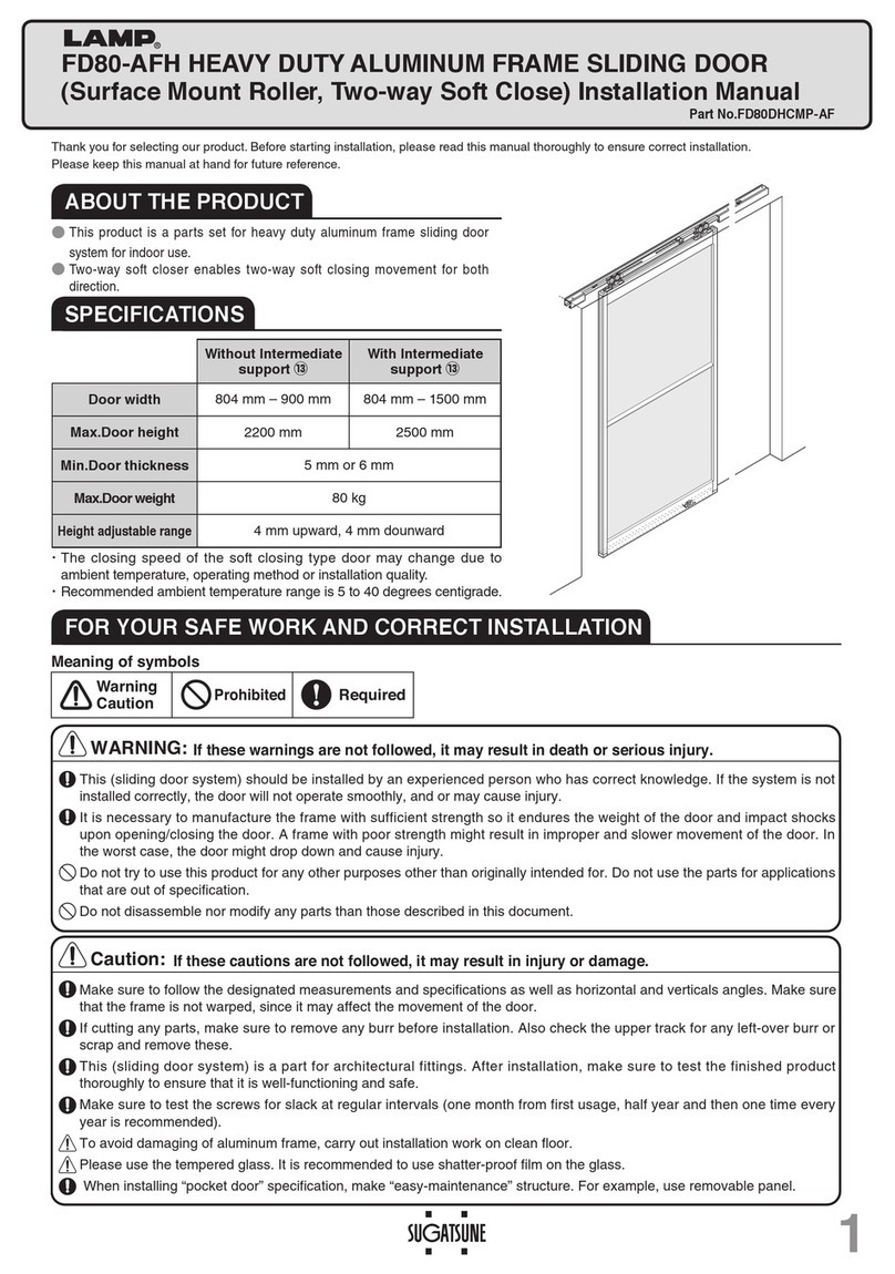
SUGATSUNE LAMP FD80-AFH User manual

SUGATSUNE

SUGATSUNE LAMP FD80-AFH User manual

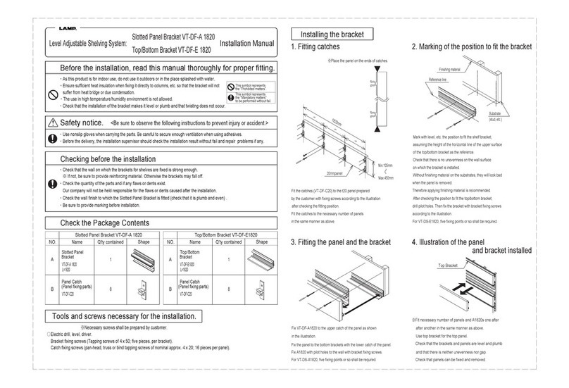
SUGATSUNE VT-DF-A 1820 User manual

SUGATSUNE

SUGATSUNE VT-DF-A 1820 User manual

SUGATSUNE LAMP FD80-H User manual

SUGATSUNE

SUGATSUNE LAMP FD80-H User manual

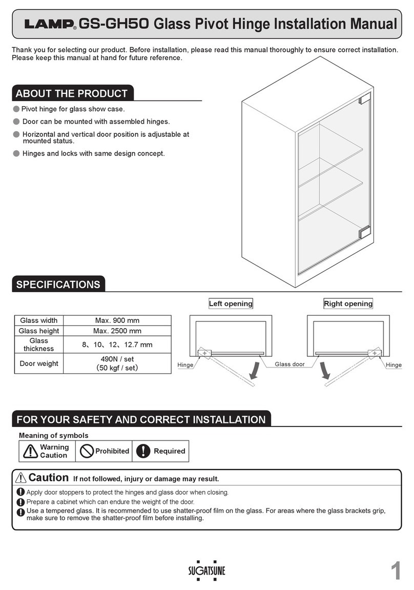
SUGATSUNE LAMP GS-GH50 User manual

SUGATSUNE

SUGATSUNE LAMP GS-GH50 User manual

Popular Indoor Furnishing manuals by other brands

Bechara DUBAI Product Guide and Assembly Instructions

Bechara

Bechara DUBAI Product Guide and Assembly Instructions

Altair WILDY 546048-BO-GW-NM manual

Altair

Altair WILDY 546048-BO-GW-NM manual

Jysk CARDIFF 726-21-1003 manual

Jysk

Jysk CARDIFF 726-21-1003 manual

Otto MONA 33 Assembly instructions

Otto

Otto MONA 33 Assembly instructions

PUIG 20330 Mounting instructions

PUIG

PUIG 20330 Mounting instructions

Inval ES 9303 Assembly Instructions and Warranty

Inval

Inval ES 9303 Assembly Instructions and Warranty

LILOLA HOME 81354 Assembly instruction

LILOLA HOME

LILOLA HOME 81354 Assembly instruction

Bouclair 9403343 Assembly instructions

Bouclair

Bouclair 9403343 Assembly instructions

Next WESTCOTT 127530 Assembly instructions

Next

Next WESTCOTT 127530 Assembly instructions

Classic Exhibits visionary MOD-1294 quick start guide

Classic Exhibits

Classic Exhibits visionary MOD-1294 quick start guide

Zest Lily Relax Seat Assembly instructions

Zest

Zest Lily Relax Seat Assembly instructions

John Lewis 86203502 quick start guide

John Lewis

John Lewis 86203502 quick start guide

Habitat Allegro 971901 manual

Habitat

Habitat Allegro 971901 manual

Costcare Bariatric B142C user manual

Costcare

Costcare Bariatric B142C user manual

Staples 21840 easy instructions

Staples

Staples 21840 easy instructions

Kvik H560-060 Assembly instructions

Kvik

Kvik H560-060 Assembly instructions

VIVO HOME VH961 Assembly instructions

VIVO HOME

VIVO HOME VH961 Assembly instructions

AKARI ZENITH 1800 BLK Assembly instructions

AKARI

AKARI ZENITH 1800 BLK Assembly instructions

manuals.online logo
manuals.online logoBrands
  • About & Mission
  • Contact us
  • Privacy Policy
  • Terms and Conditions

Copyright 2025 Manuals.Online. All Rights Reserved.