SUGATSUNE LAMP FD80-AFH User manual

1
FD80-AFH HEAVY DUTY ALUMINUM FRAME SLIDING DOOR
(Surface Mount Roller, Two-way Soft Close) Installation Manual
Part No.FD80DHCMP-AF
Thank you for selecting our product. Before starting installation, please read this manual thoroughly to ensure correct installation.
Please keep this manual at hand for future reference.
ABOUT THE PRODUCT
●
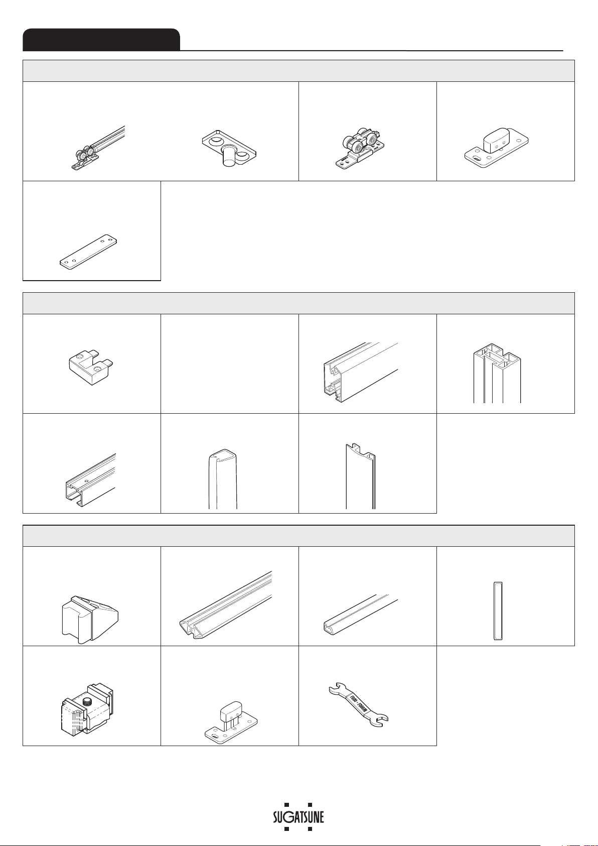
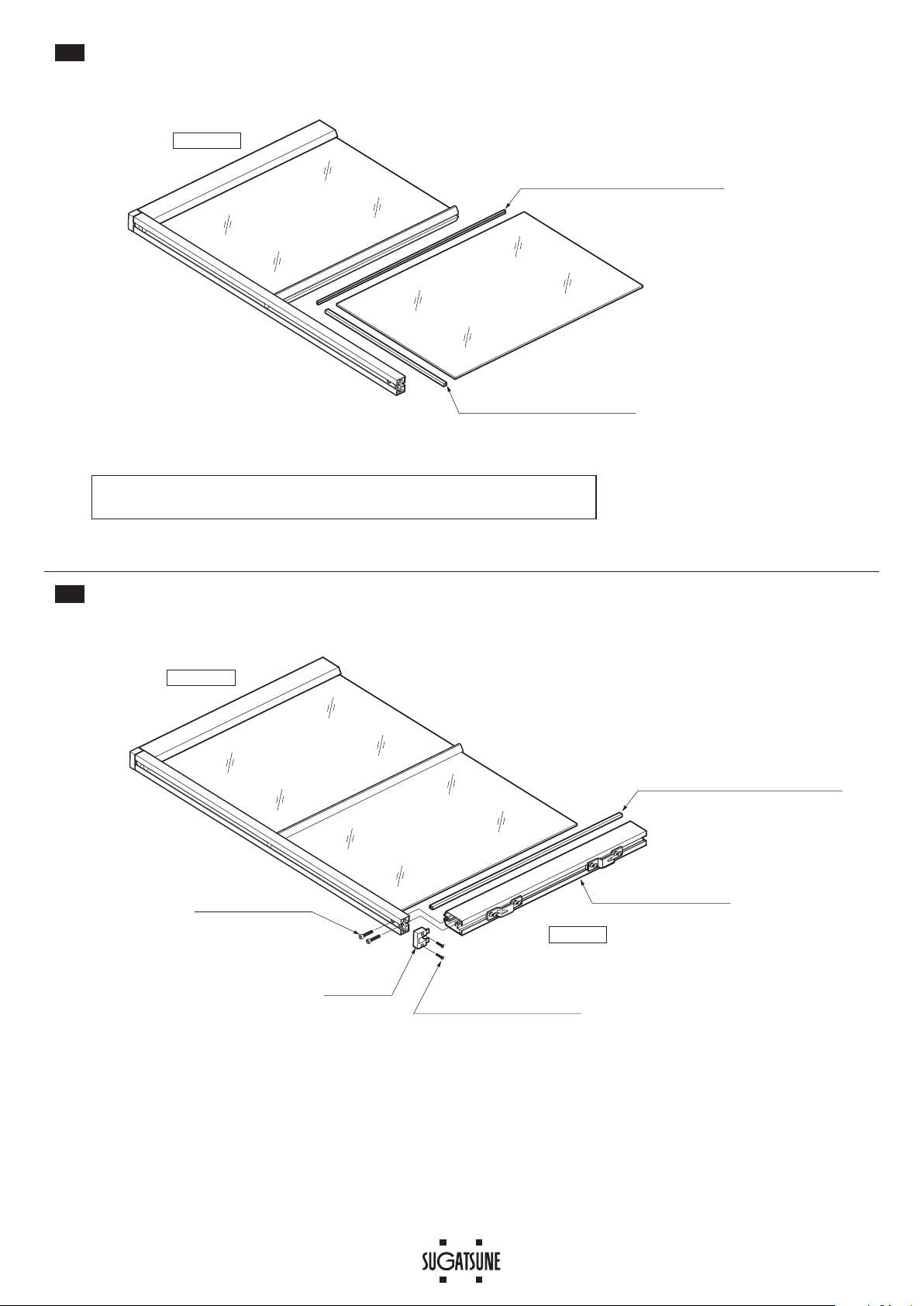
This product is a parts set for heavy duty aluminum frame sliding door
system for indoor use.
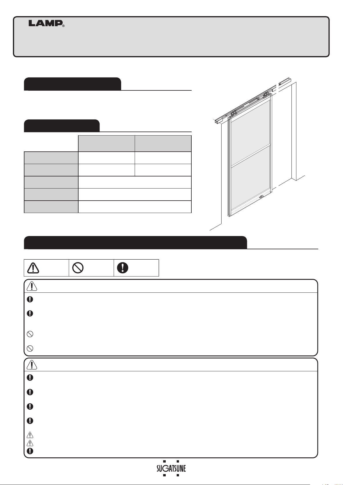
●
Two-way soft closer enables two-way soft closing movement for both
direction.
SPECIFICATIONS
・
The closing speed of the soft closing type door may change due to
ambient temperature, operating method or installation quality.
・
Recommended ambient temperature range is 5 to 40 degrees centigrade.
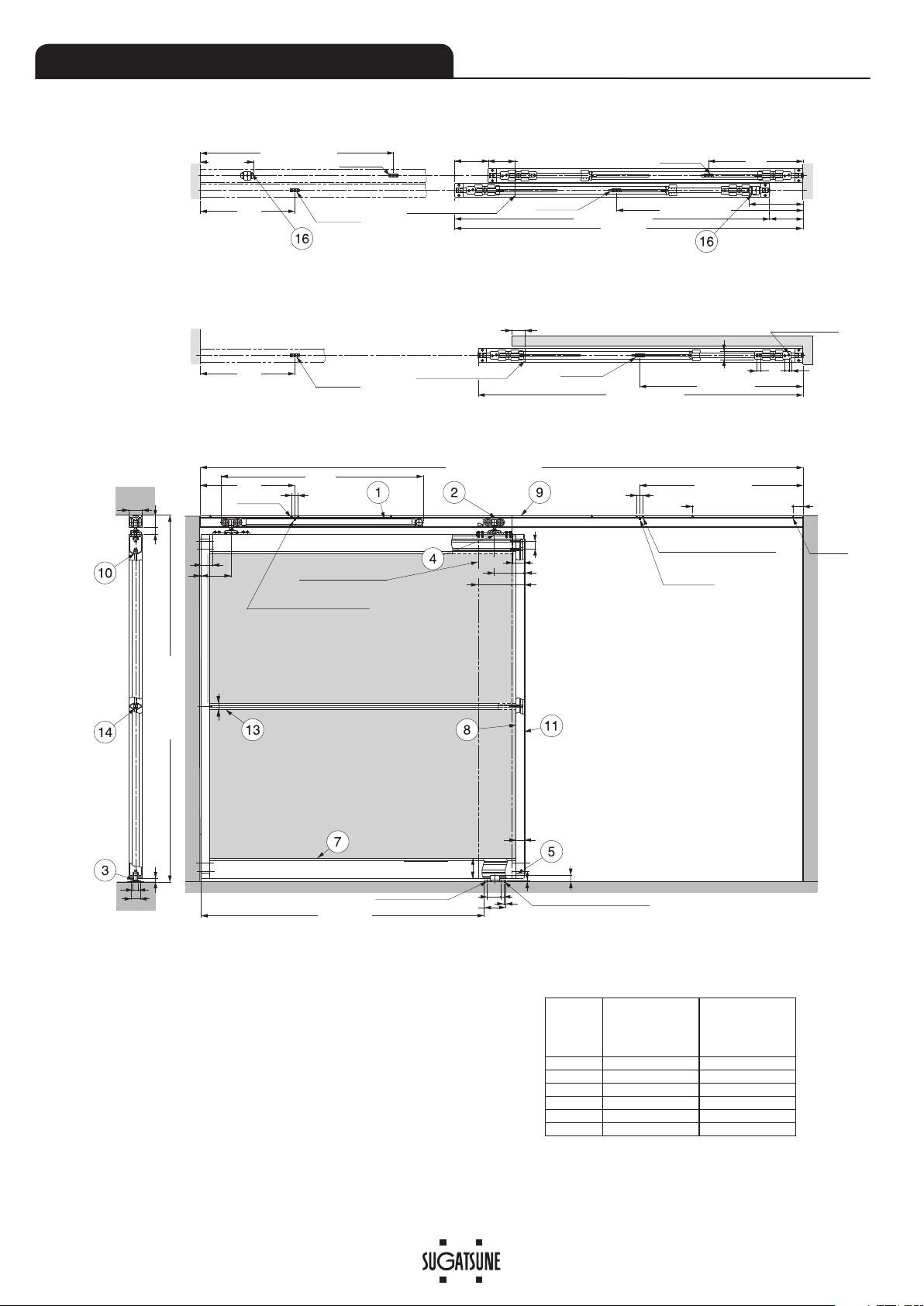
Without Intermediate
support ⑬
With Intermediate
support ⑬
Door width 804 mm – 900 mm 804 mm – 1500 mm
Max.Door height 2200 mm 2500 mm
Min.Door thickness 5 mm or 6 mm
Max.Door weight 80 kg
Height adjustable range
4 mm upward, 4 mm dounward
FOR YOUR SAFE WORK AND CORRECT INSTALLATION
WARNING:
If these warnings are not followed, it may result in death or serious injury.
Caution:
If these cautions are not followed, it may result in injury or damage.
This (sliding door system) should be installed by an experienced person who has correct knowledge. If the system is not
installed correctly, the door will not operate smoothly, and or may cause injury.
It is necessary to manufacture the frame with sufficient strength so it endures the weight of the door and impact shocks
upon opening/closing the door. A frame with poor strength might result in improper and slower movement of the door. In
the worst case, the door might drop down and cause injury.
Do not try to use this product for any other purposes other than originally intended for. Do not use the parts for applications
that are out of specification.
Do not disassemble nor modify any parts than those described in this document.
Make sure to follow the designated measurements and specifications as well as horizontal and verticals angles. Make sure
that the frame is not warped, since it may affect the movement of the door.
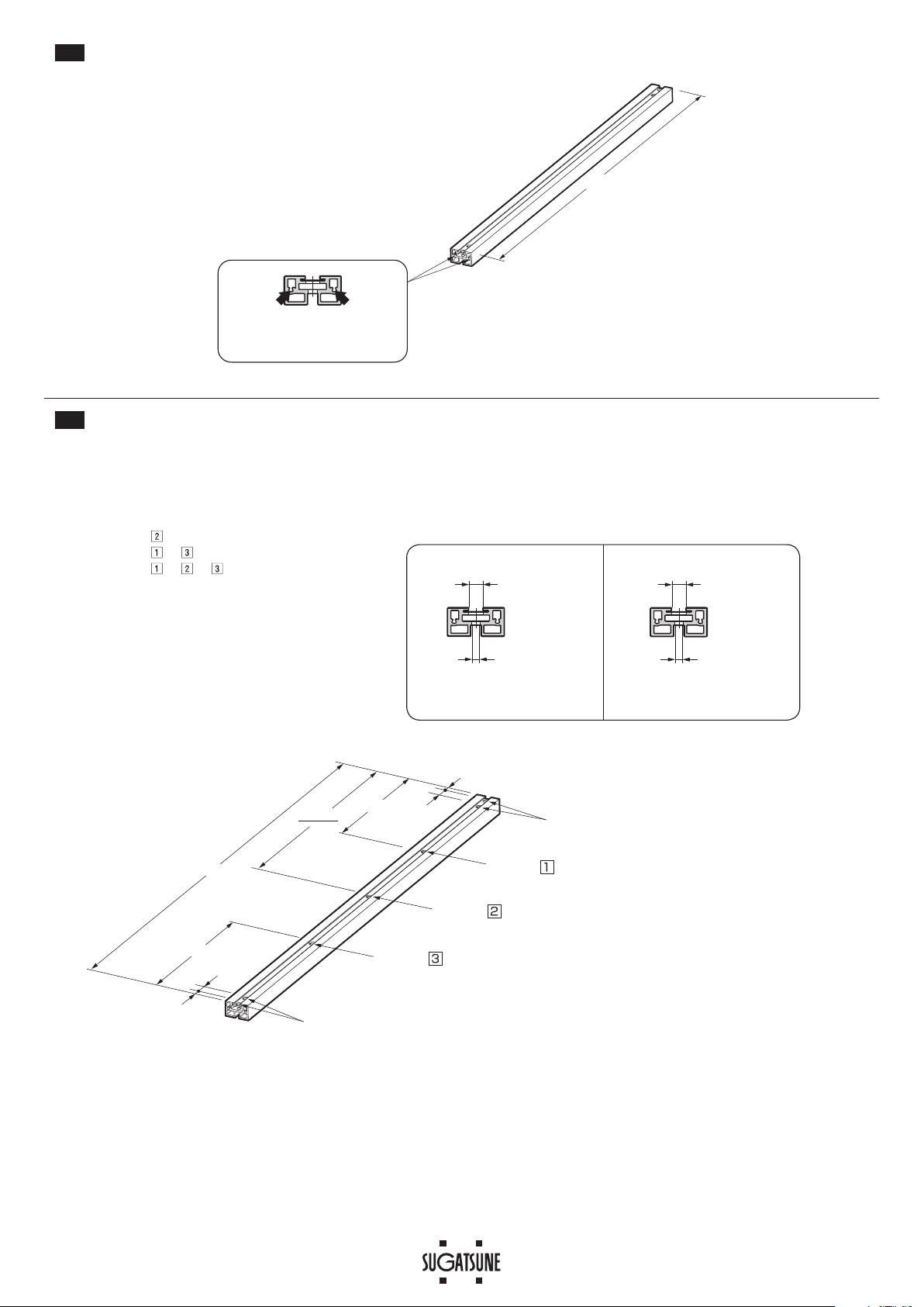
If cutting any parts, make sure to remove any burr before installation. Also check the upper track for any left-over burr or
scrap and remove these.
This (sliding door system) is a part for architectural fittings. After installation, make sure to test the finished product
thoroughly to ensure that it is well-functioning and safe.
Make sure to test the screws for slack at regular intervals (one month from first usage, half year and then one time every
year is recommended).
To avoid damaging of aluminum frame, carry out installation work on clean floor.
Please use the tempered glass. It is recommended to use shatter-proof film on the glass.
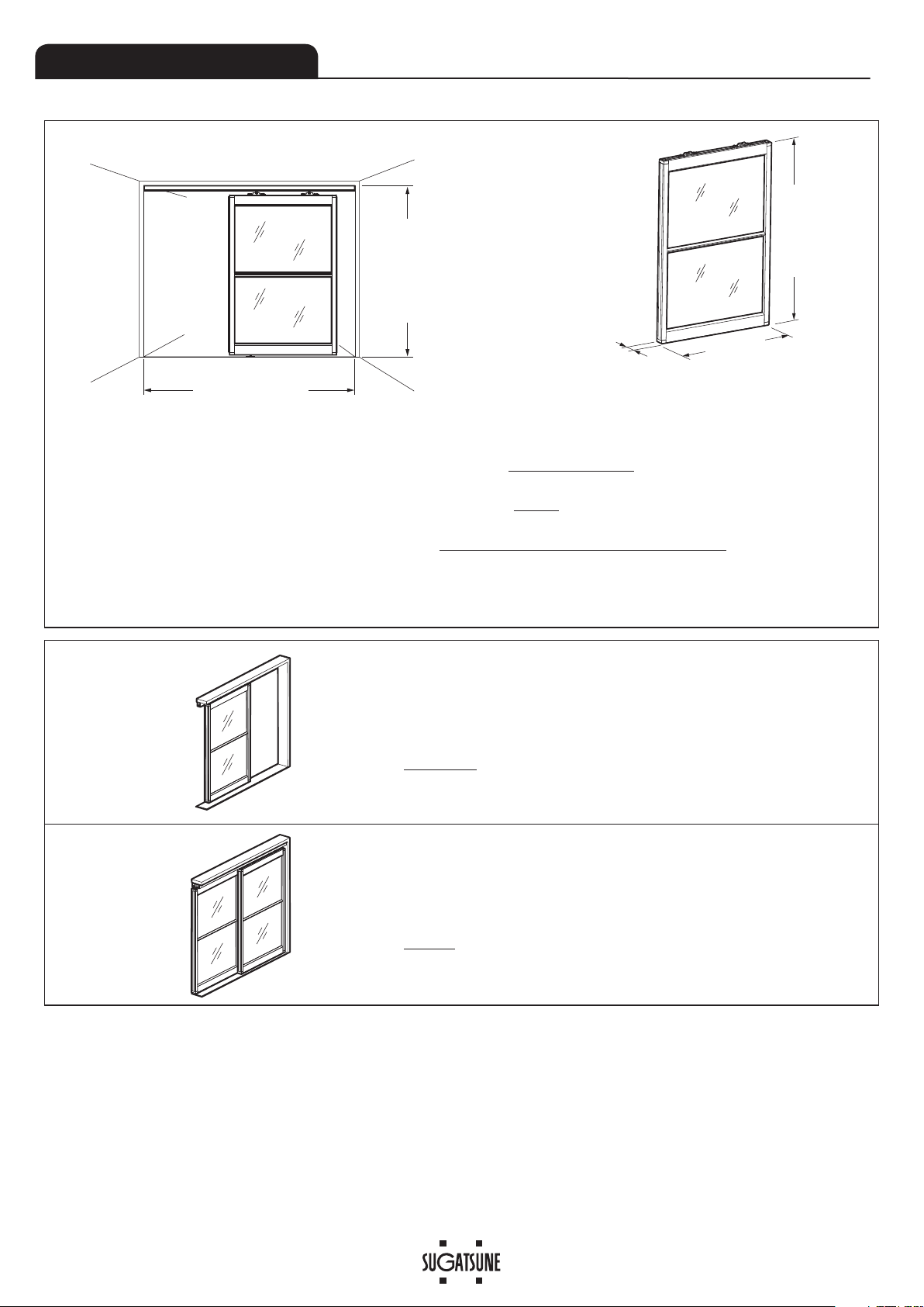
When installing “pocket door” specification, make “easy-maintenance” structure. For example, use removable panel.
Prohibited
Warning
Caution Required
Meaning of symbols

2
Nominal designation 10, 12
Trigger
COMPONENT PARTS
Optional parts
⑫Door stopper (floor)
Item No. : FD30-HTKY
Accessory screw : Bind head tapping
screw 4×30
………………
3 pcs
Needed when vertical frame is not used.
⑬Intermediate support
Item No. : AF-25-W03
2000 mm
⑭
Gasket for Intermediate support
Item No. : for 5 mm glass
…
AF-25-P03
for 6 mm glass
…
AF-25-P16
2500 mm
⑮Handle
Item No. : WN799Z160E101
It is adhered after drilling two 7 mm dia.
holes.
⑯Stopper block
Item No. : FD80-HSB
This is used in the upper track.
⑰Floor guide L
Item No. : FD50-BG32
Accessory screw : Bind head tapping
screw 4×16
………………
5 pcs
This is used when larger space below
the door is required.
⑱Spanner
Item No.FD30-FSP
Parts set (FD80DHCMP-AF) per door
①Two-way Soft Closer (surface mount) + Trigger
Accessory screw : Pan head tapping screw 4 x 45 ………………………………… 4 pcs (not needed for this set)
Countersunk head tapping screw 4 x 30(φ6head)…………… 4 pcs (for trigger)
②
Upper roller (surface mount)
Accessory screw : Pan head tapping screw
4 x 45…………………………… 4 pcs
(not needed for this set)
③Floor guide S
Accessory screw : Bind head
tapping screw 4 x 16 ………… 5 pcs
④Plate nut
Accessory screw : Hexagon socket button head
screw M5 x 16 ……………… 8 pcs
Spring lock washer 5 ……… 8 pcs
Plain washer 5 ……………… 8 pcs
Required Parts
⑤Corner Part ⑥Mount screw set
・
Hexagon socket head cap screw M6 x 30 …… 8 pcs
(for Frame⑦⑧)
・Hexagon socket head cap screw M4 x 30 …… 6 pcs
(for Intermediate support⑬)
・
Hexagon socket countersunk head screw
M4 x 25 …… 8 pcs
(for Corner Part⑤)
⑦Horizontal frame
2000 mm
⑧Vertical frame
2500 mm/3000 mm
⑨Upper track(Various sizes)
Accessory screw : Pan head tapping screws 5×40
⑩Gasket
for 5 mm glass : 2500 mm
for 6 mm glass : 3000 mm
⑪Edge cover
2500 mm/3000 mm
2 pcs1 pc 1 pc 1 pc
1 set
4 pcs / door 1 set

3
Door end when fully closed
Inside height FH
ϕ5.5
hole
(Install in track.) (Install in track.)
Trigger1
Trigger2 Trigger1
Trigger2
Double sliding
Single sliding
Part set:Use 2 sets of
FD80DHCMP-AF
40(Overlap)
Margin DN
16
28
10《24》*
40
34
20±4*
35
290
35 90
24
2
282
DW-483+DN*Margin DN
DW+DN
282
Door width DW
DN
Opening width FW
Door width DW
18
DW-483+DN*
DW-483*
30
DN+60
DN+60
40(Overlap)
40(Overlap)
Track hole pitch 300
604.5
7
12
72
12
25
4
×
5.2
×
8.2
Elongated hole
25
18
Trigger1
DW-483*
Trigger1
Trigger2
Door end when fully closed
1919
60
282
282
41 95
64
(
FW/2
)
-32
3
18《32》*
4×ϕ4.5 hole 4.5×9.5 Elongated hole
Trigger mount holes
2×
ϕ5
(additional)
Trigger mount holes
2×
ϕ5
(additional)
Trigger 2
1
1
2
2
3
4
4
*
INSTALLATION DRAWING (EXAMPLE)
Refer to page 4 about the dimensions of the doors and glass panels.
*3Height adjustable range : -4 mm to +4 mm.
*4Dimension《》 : when floor guide L⑰(optional) is used.
INSTALLATION DIMENSIONS FOR TRIGGER 2
Please add the Margin DN to dimension for
Trigger 2, if you are using a protruding handle.
Example shown below.
DW
[Margin DN=0 mm]
Installation dimension for
Trigger 2
【ForDoubleslidingonly】
Example [Margin DN=70 mm]
DW-483+DN is the Installation
dimension for Trigger 2
1,000 517 587
1,100 617 687
1,200 717 787
1,300 817 887
1,400 917 987
1,500 1,017 1,087
*1
*2

4
FW (Opening width)
FH (Inside height)
40 (Door thickness)
DW (Door width)
DH (Door height)
DIMENSIONS OF DOORS
■Drawing of installed door
Ex: 1 door on single track
Size of the door when Opening width 1800 mm and Opening height 2400 mm with 80 mm of margin
DH = 2400−64
= 2336 mm
DW = 1800+80+40
2
= 960 mm
Ex: 2 door on single track
Size of each door when Opening width 1800 mm and Opening height 2400 mm
DH = 2400−64
= 2336 mm
DW = 1800+40
2
= 920 mm
DH (Door height) = FH−64
Single sliding DW (Door width) = FW+DN (Margin) +40
2
Double sliding DW (Door width) =FW+40
2
GH (Glass height) = DH−104− (Number of Intermediate support⑬x 11)
Number of glass panels
GW (Glass width) = DW−34
Example 1
Example 2
(Cut off after the decimal point for the divided dimensions.)

5
263
2×ϕ5 additional hole
(For trigger mount)
2×ϕ5 additional hole
(For trigger mount)
ϕ5.5 additional hole
(For track fixing)
A-492*
30
18 18
273
FW (Opening width)
About dimension A (See the drawing on page 3 for the detail.)
Single sliding
A = DW (Door width)
= FW (Opening width) + DN (Margin) + 40
2
Double sliding
A = DW (Door width) + DN (Margin)
= FW (Opening width) + 40 + DN (Margin)
2
Cutting and hole processing of standard length parts
1
INSTALLATION PROCEDURE
・
Cut carefully so the cut edge is square to avoid bias and skewing.
・
Make sure to remove any burr. Also check the upper track for any left-over
burr or scrap and remove these.
Caution
This procedure explains installation of single sliding door system.
1-1 Processing of Upper track⑨
Length = FW (Opening width)
Refer to the figure on the right for cutting and
drilling holes.
DW (Door width) - 50
M6 threading Min. depth 20 mm
2 holes at each end.
1-2 Processing of Horizontal frame⑦
Length = DW(Door width) - 50 (Thickness of Vertical frame x 2)
M4 threading Min. depth 20 mm
1 hole at each end.
DW (Door width) - 50
Length = DW(Door width) - 50 (Thickness of Vertical frame x 2)
1-3 Cutting and hole processing of Intermediate support⑬, when used

6
DH (Door height) -30
M4 threading Min. depth 20 mm
2 holes at each end.
DH−30
2
DH−30
6.5
GH+42.5
24
6.5
GH+42.5 24 Hole A
Hole A
Hole B
Hole B
Hole B
Hole A
ϕ10.5 hole
ϕ6.2 hole
Hole B
ϕ8 hole
ϕ4.2 hole
1-5 Processing of Vertical frame⑧- Step 2
Drill holes according to the quantity of Intermediate support.
Hole A only if there is no Intermediate support
Hole A + B for 1 Intermediate support
Hole A + B , B for 2 Intermediate supports
Hole A + B , B , B for 3 Intermediate supports
1-4 Processing of Vertical frame⑧- Step 1
DH: Door height
GH: Glass height

7
282
DW-483
*
(single sliding)
Countersunk head tapping
screw 4×30(φ6head)
(Attached to①)
64
Door (tail end)
32
⑨Upper rail
③Floor guide S
*2
Correct set position
Trigger catcher
Correct set position
If the closer is installed without conformation,
it will cause the trouble such as no-sliding of door.
ϕ6
If the position is wrong, pull back the trigger catcher to
the correct position using 6 mm diameter hard bar.
Incorrect set position
OK (Red colored part)
Caution
Leading edge
Trailing edge
⑨Upper track
②Upper roller
①Two-way
soft closer
(①②)Bracket
(①②)Holder
①②Upper roller
Remove
Assembling parts
2-1 Disassembling Rollers
Remove upper roller bracket and holder.
2-2 &RQÀUPDWLRQEHIRUHLQVWDOOLQJ7ZRZD\VRIWFORVHU 2-3 Assembly of parts for track
(1) Assemble the parts in order of ①to ②with care of direction.
(2) Tape around rollers and upper track to prevent drop of
inserted parts.
Installing Upper track⑨, Trigger①, and Floor guide S③
①Two-way
soft closer
②Upper roller
Leading edge
Leading edge
Trailing edge
*Double sliding:DW-483+DN
The leading edge
of the track has two
5 mm dia. holes at
282 mm position
from the end.
The leading edge
of the track has two
5 mm dia. holes at
282 mm position
from the end.
3-2 Installing Trigger①
According to "Installation Drawing
(Example)", install triggers with attached
screws.
3-3 Installing Floor guide S③
Install the Floor guide so that it stays under
the door when it is opened or closed.
3-1 Mounting Upper track⑨
Confirm that leading edge of the upper
track is in same direction as the leading
edge of the door.
Fix the upper track with attached screws.
2
3
*2
Bind head tapping
screw 4×16
Pan head
tapping screw
5×40
(Attached to ⑨)

8
Hex key (3 mm)
Hexagon socket button head screw M5 x 16 (Accessory of ④)
Spring lock washer 5 (Accessory of ④)
Plain washer 5 (Accessory of ④)
Bracket
④Plate nut
⑦Horizontal frame<upper>
125
125
Bottom side
⑦Horizontal frame (lower)
⑤Corner part
⑥Hexagon socket countersunk
head screw M4 x 25
⑥Hexagon socket head
cap screw M6 x 30
⑧Vertical frame
4-1 Preparation of Horizontal frame⑦- Upper
Assembling door
Set the Bracket to upper Horizontal frame ⑦, using Plate nut ④.
The distance from the edge and Bracket center should be 125 mm.
・Coat screw threads with anti-loose material such as "thread locking".
・During door installation, handle the glass carefully to prevent injury.
4-2 Assembly of Horizontal frame⑦(lower) and Vertical frame⑧
4
Caution

9
Bottom side
⑩Gasket
⑩Gasket
Glass
Horizontal length: DW (Door width) - 50
Vertical length: GH (Glass height)
Glass
⑭Gasket
Horizontal length: DW (Door width) - 50
⑥Hexagon socket head
cap screw M4 x 30
⑬Intermediate support
Bottom side
4-3 Insertion of glass - Step 1
4-4 Assembly of Intermediate support⑬, when used

10
Glass
Glass
⑭Gasket
Horizontal length: DW (Door width) - 50
⑩Gasket
Vertical length: GH (Glass height)
Bottom side
Glass
Glass
⑩Gasket
Horizontal length: DW (Door width) - 50
⑥Hexagon socket head
cap screw M6 x 30
⑤Corner part
⑦Horizontal frame (upper)
⑥Hexagon socket countersunk
head screw M4 x 25
Top side
Bottom side
4-5 Insertion of glass - Step 2, when Intermediate support is used
4-6 Assembly of Horizontal frame⑦(upper)
When using more than two Intermediate supports, repeat procedures 4-4 to 4-5.

11
Glass
Glass
⑩Gasket
Vertical length: GH (Glass height)
⑥Hexagon socket head
cap screw M6 x 30
⑤Corner part
⑥Hexagon socket countersunk
head screw M4 x 25
⑥Hexagon socket head
cap screw M4 x 30
Bottom side
Top side
Glass
Glass
⑪Edge cover
Length: LV
(Vertical frame⑧)
Use synthetic rubber
adhesive in a few
places to prevent the
Edge cover⑪from
shifting.
Bottom side
Top side
Spatel
4-7 Assembly of Vertical frame⑧
Bend the Edge cover⑪
between your fingers
and press it into the side
of the Vertical frame.
Before attaching the Edge covers, make sure the frame is not biased
or skewed, and that all bolts are tight.
Make sure the parts are firmly assembled and there is no warping or
skewing.
4-8 Assembly of Edge covers⑪
You may find the Gasket coming off from the frame.
In such case, use a Spatel or something to push it in and be careful not to
scratch the glass.
Caution

12
③
Floor guide S
Be sure to have someone with knowledge
and experience assist you.
Hanging the door
5
Caution
(1)
(2)
(1) Put a support below the door to be hanged. Tilt the door as shown in the
figure, and set the Floor guide S③to the groove of the bottom Horizontal
frame⑦.
(2) Push the door and set the hanger bolts as shown in the figure below.
(2)
(2)

13
Right angle
Pull the wrench at a right angle
away from the door.
*
Frame Frame
⑫Door stopper
(Optional)
Up
Down
PP
PP
①②Holder
Installing Door stopper⑫(Option)
&RQÀUPLQJ7ZRZD\VRIWFORVHURSHUDWLRQ
Make sure to install the Door stopper⑫when vertical frame is not used.
(1) Slowly move the door toward door head, and confirm that sliding
door closer starts its function at approx. 100 mm before full-close
position.
(2) Also, confirm that the door closer starts its function at approx. 100
mm before full-open position.
If the closer is not working correctly, check the Troubleshooting
section.
8
7
Adjustment of door height
(1) Remove the support under the door.
(2) Turn the bolt and adjust the height of the door.
The height adjustment range is +4 mm to -4 mm from factory setting
(totally 8 mm).
(Tool: nominal 10 wrench, max. 6 mm thick)
(3) After adjusting the door, pull the wrench at a right angle away from the door.
Make sure the width across flats of the bolt head is as shown in the figure*.
6
Leading edge Trailing edge
①Trigger
about 100 mm about 100 mm
①Trigger
(4) Insert the holder as shown below.

Holder (①②)
Periodical
Inspection
・Clean inside of track.
・Check upper space and lower space of the door. If necessary, correct the space.
(3) Pull out the Upper roller from the Bracket.
TROUBLESHOOTING
HOW TO REMOVE DOOR
Trouble Checkpoint Solution
Door stops during soft
closing
Check if door bottom contacts with floor. Confirm that track fixing screws are not loosened. Then, adjust door height
such that clearance between door bottom and floor becomes 6 - 13 mm.
Check if upper track is set horizontally. Using a level gauge, reset upper track horizontally.
Check if mohair seal is installed. Reduce the friction between mohair and door.
No soft closing Check if trigger is installed. Install trigger to correct position.
Check if door is closed by excessive force. Do not close door by excessive force and it may damage soft closer.
The position of trigger catcher might change to the
incorrect positioninside the track. (See section .)
Slowly moving the door toward leading edge side, then push the door firmly.
Repeat this action to the opposite sideas well.
If it is still not improved, check the status of trigger catcher in section .
Abnormal noise during
operation
Check if door touches other parts. Provide necessary space between door and adjacent objects.
Check track rollers for aluminum dust. Remove the track and pull out the roller. Then, clean the roller.
Check for loose screws retaining the upper track. Tighten the screw.
Heavy door operation Check if door touches adjacent parts. Correct door position to avoid contact to other objects.
Adjust position of floor guide or stopper.
Check if door is warped. Use a door without warp.
Door does not move. Check track retaining screws for looseness. Roller touches with screw.
Retighten screws to free the roller.
2-2
2-2
2-2
2016.11 0582-5
Table of contents
Other SUGATSUNE Indoor Furnishing manuals
Popular Indoor Furnishing manuals by other brands

brenton
brenton Studio Merido Collection Desk OM03495 manual

Steelcase
Steelcase Elective Elements Storage manual

FORM & REFINE
FORM & REFINE POSITION BENCH 155 Assembly guide

Novogratz
Novogratz DA8054 instruction manual

Grohe
Grohe Axor Massaud Lavatory Mixer 18010001 installation instructions

Enwork
Enwork Landing Installation instruction