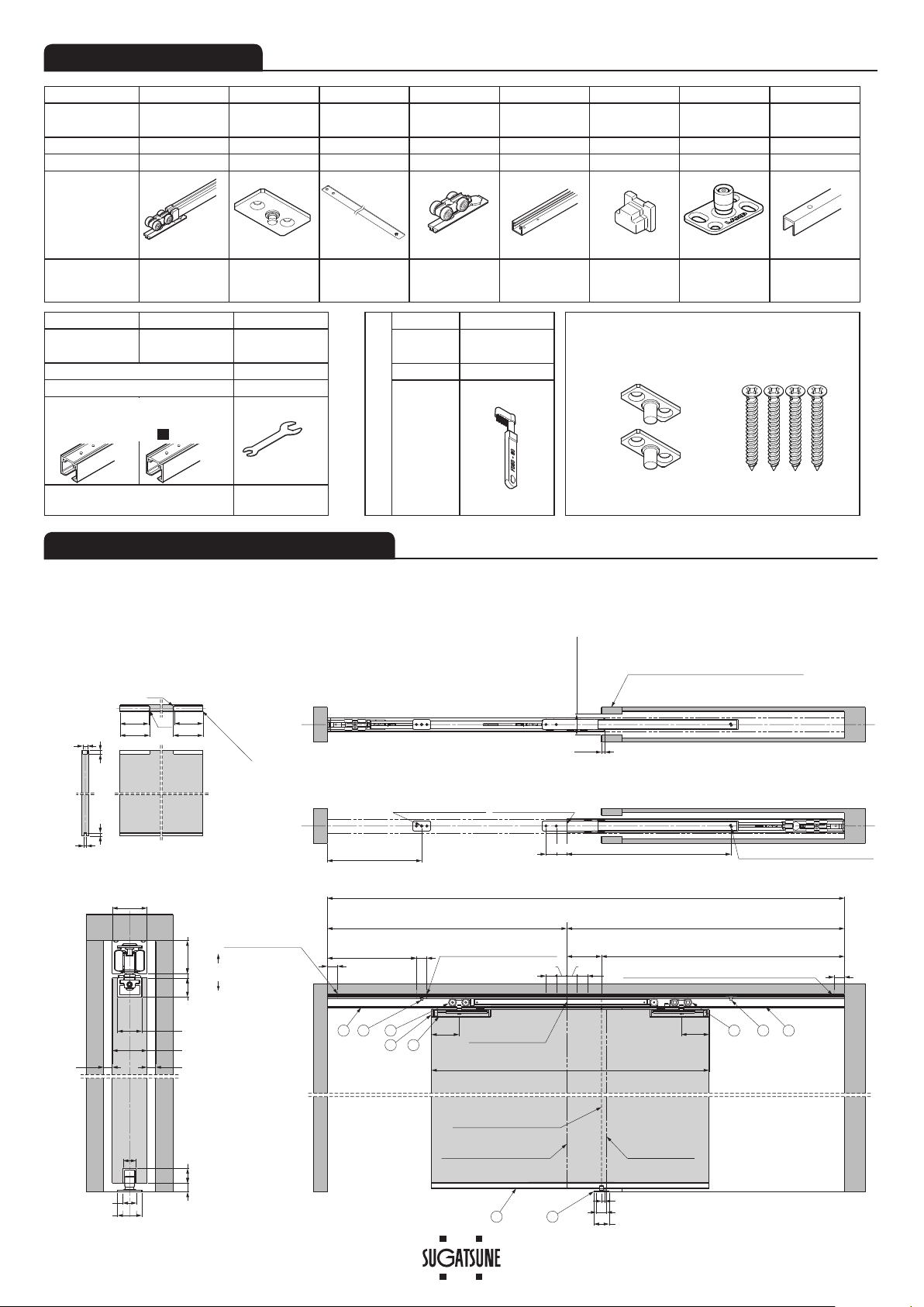
SUGATSUNE LAMP FD80-H User manual

1
Door
Door pocket
FD80-H HEAVY DUTY SLIDING DOOR SYSTEM Installation Manual
(Ceiling Mount Type for Pocket Door, with Two-way Soft Close)
Part No.FD80DHCHP-PD
Door height
Max. 2500 mm 2501
–
2700 mm
Door width
784
–
1500 mm 850
–
1500 mm
Min. Door thickness 34 mm
Max. Door weight 80 kg/door
Height adjustable range
1 mm upward, 4 mm downward
Thank you for selecting our product. Before starting installation, please read this manual thoroughly to ensure correct installation.
Please keep this manual at hand for future reference.
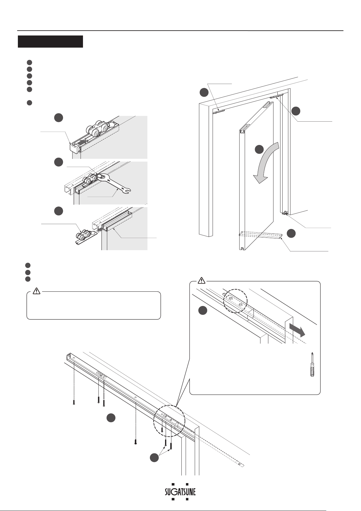
●
This is a parts set for a sliding door system for stores,
public facilities and residence.
●
Built in soft closer enables two-way soft closing movement
for both direction.
●
The track can be divided for easy maintenance after
installing.
・
The closing speed of the soft closing type door may change due
to ambient temperature, operating method or installation quality.
・
Recommended ambient temperature range is 5 to 40 ℃.
FOR YOUR SAFE WORK AND CORRECT INSTALLATION
ABOUT THE PRODUCT
SPECIFICATIONS
Warning :
Caution : If these cautions are not followed, it may result in injury or damage.
Prohibited
Warning
Caution Required
Meaning of symbols
If these warnings are not followed, it may result in death or serious injury.
Do not try to use this product for anything other than its original purpose. Do not use any part for applications outside of its
specification.
Do not disassemble nor modify any parts other than those described in this document.
This (sliding door system) should be installed by a qualified person. If the system is not installed correctly, the door will not
operate smoothly, and may cause injury.
It is necessary to manufacture the frame with sufficient strength so that it endures the weight of the door and any impact
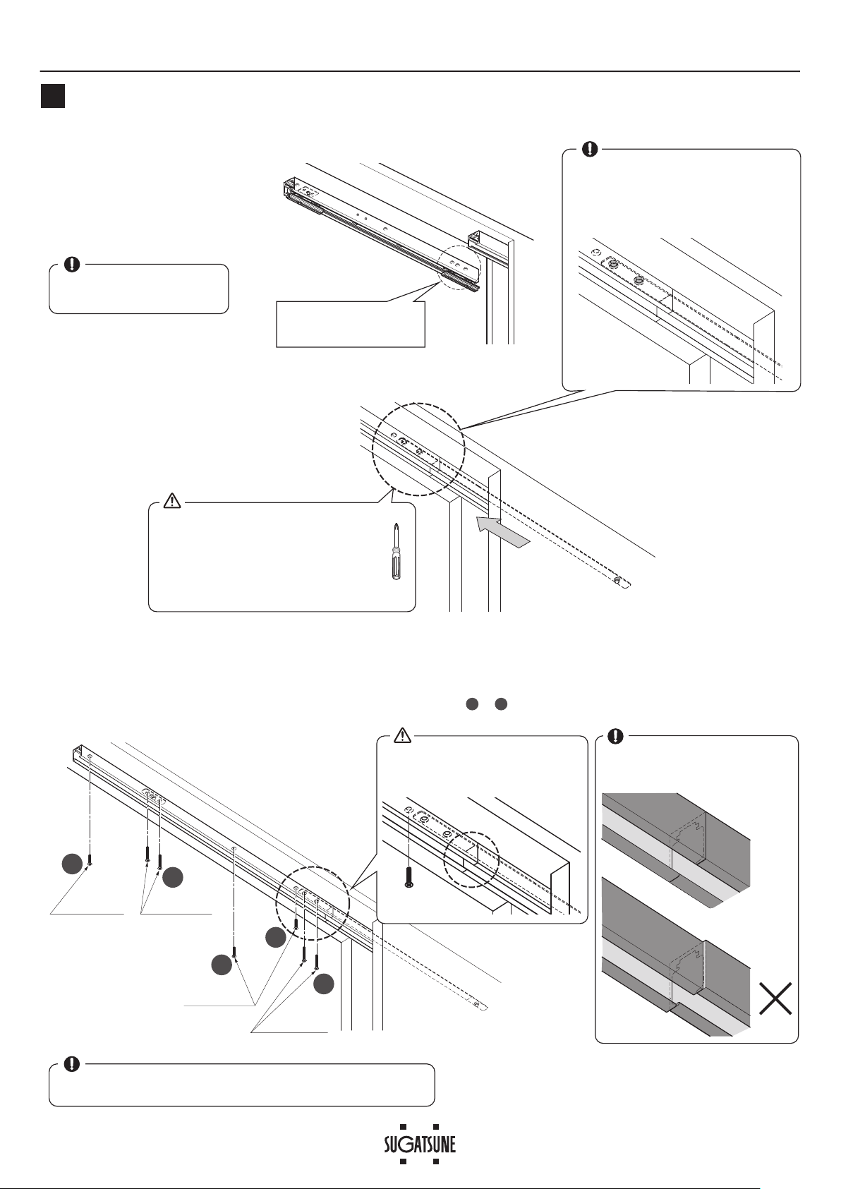
upon opening/closing the door. Only use designated screws and ensure that they are fastened firmly. A frame with poor
strength or loose screws might result in the door falling and causing injury
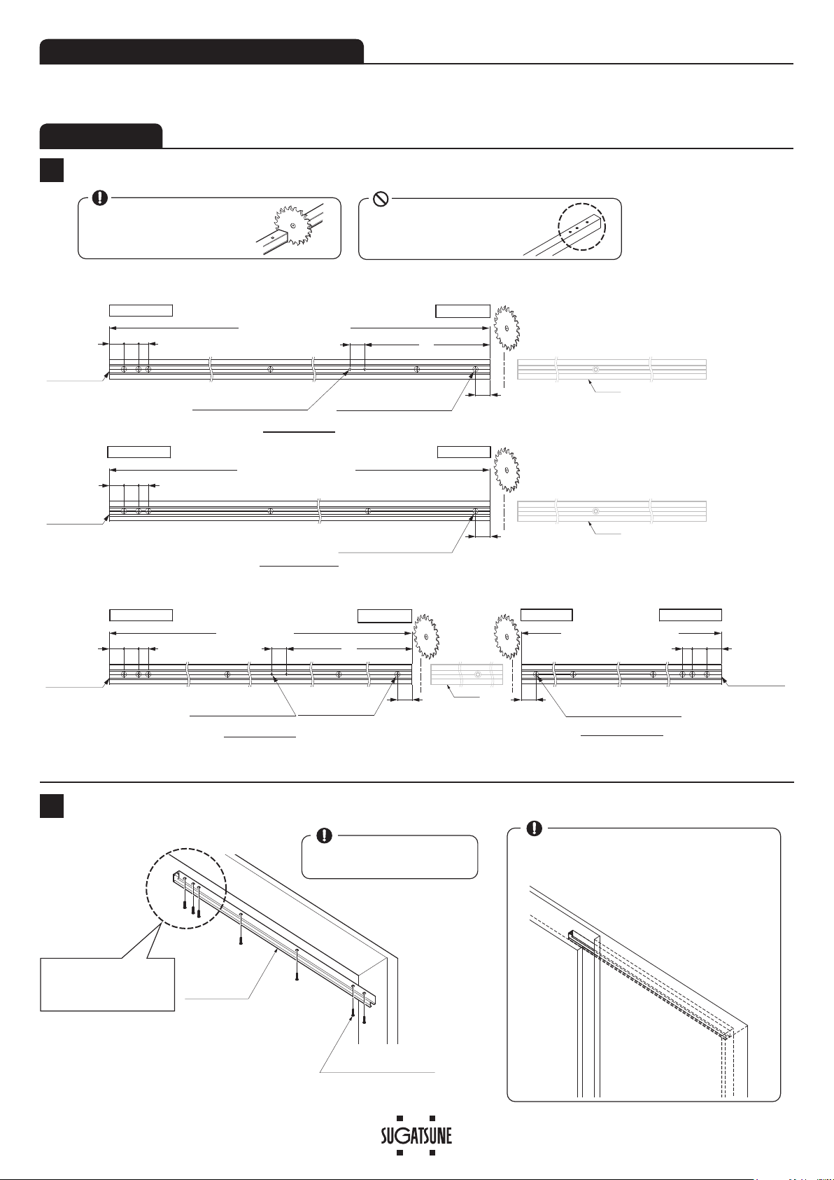
If cutting any parts, make sure to remove any burrs before installation. Also check the upper track for any left-over burrs or
scraps and remove these.
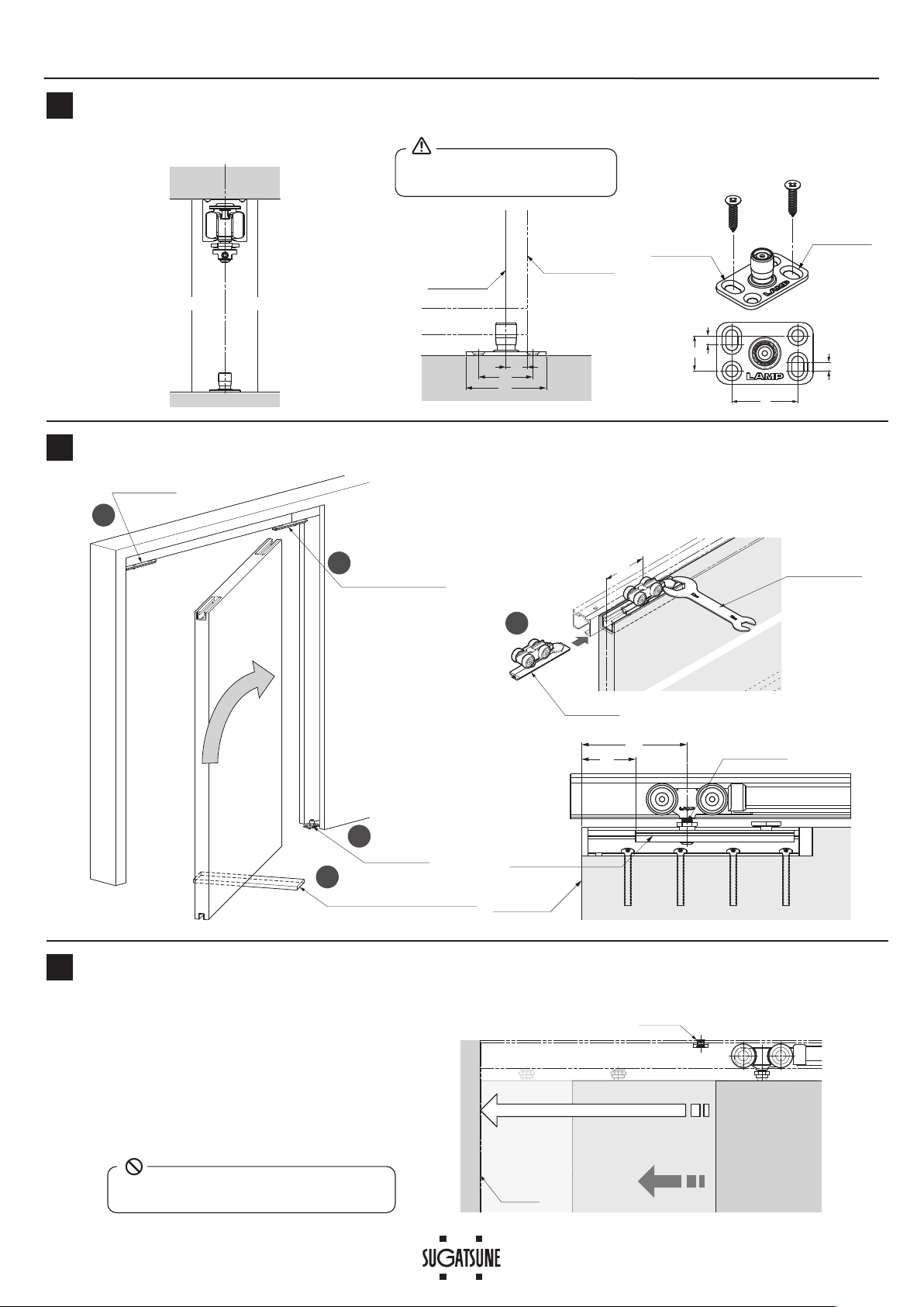
We recommend that the installation is carried out by two people, in order to ensure proper installation and avoid
unnecessary stress on the parts.
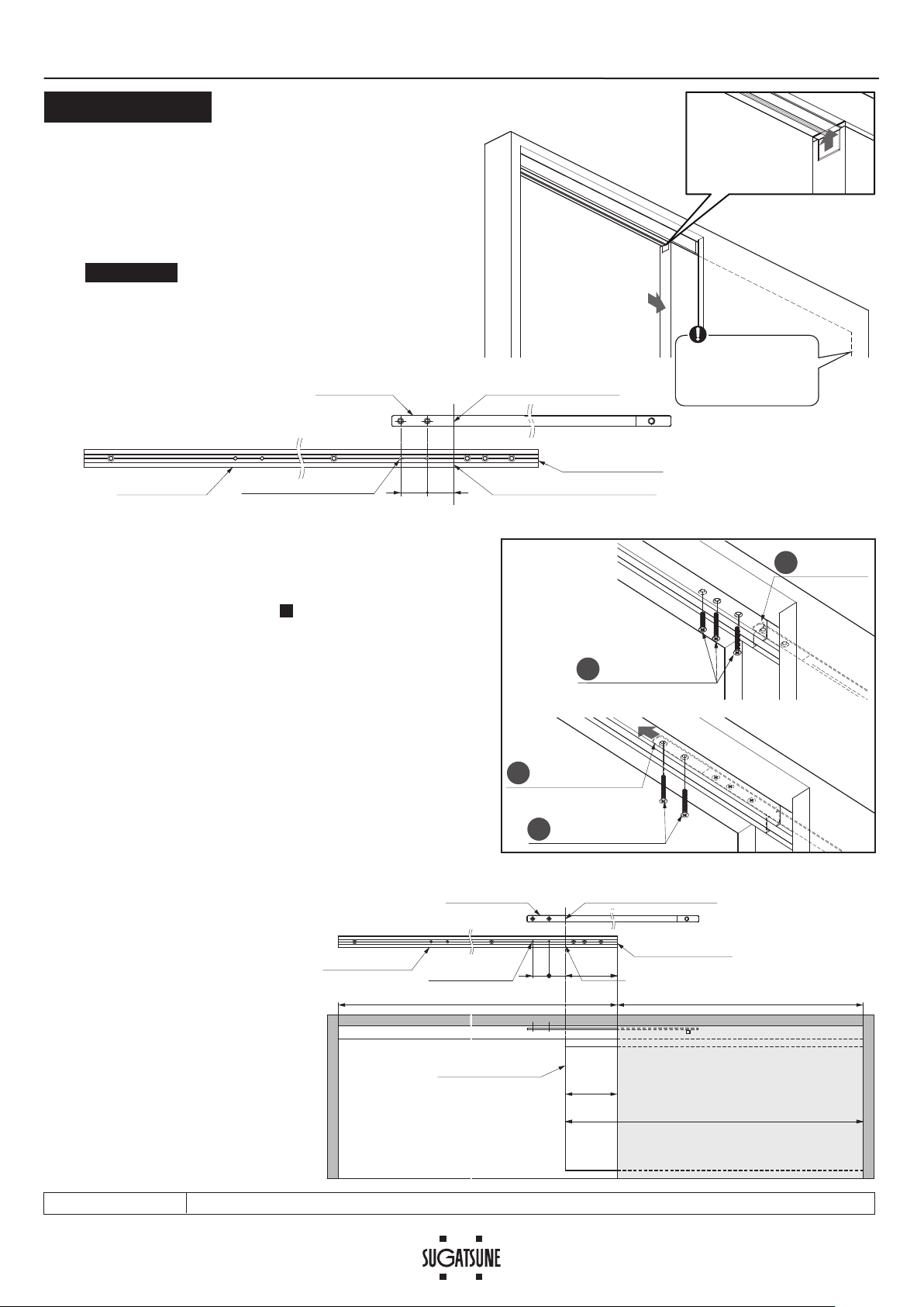
Make sure to follow the designated dimensions, specifications, and horizontal/vertical angles. Make sure that the frame is
not warped, since it may affect the movement of the door.
This product is a part for architectural fittings. After installation, make sure to test the finished product thoroughly to ensure
that it is well-functioning and safe.
Make sure to check the screws for slack at regular intervals (one month from first usage, half a year, and then one time
every year is recommended).
When installing the “pocket door” specification, make the “easy-maintenance” structure.
For example, use a removable panel.

2
No. ①②③④⑤⑥⑦⑧
Name
Recessed mount
soft closer (two-way)
Front trigger Pocket trigger
Recessed
mount roller
Hanging
bracket End cap Floor guide Door guide
track
Order code 250-022-239 250-029-709 250-025-460 250-022-241
250-120-608 250-121-142
250-029-718 250-019-971
Part No.
FD80-WRH-DSC
FD80-TRGPF
FD80-TRGPB-HB
FD80-WRH FD70B-HB160 FD70B-EC-BL FD50-BGR18
FD30-HBRT1500SIL
Parts
1 pc 1 pc 1 pc 1 pc 2 pcs 2 pcs 1 pc 1 pc
Accessories Hex key 3 mm
Countersunk head
tapping screws
4 × 40 2 pcs
Countersunk head
tapping screws
4 × 40 2 pcs
Hex key 3 mm
Pan head tapping
screws
5 x 40 4pcs
Countersunk head
tapping screw
4 x 20 4pcs
Recommended screw
: Countersunk head
tapping screws 4 × 20
⑨⑩⑪
Open area track Door
pocket track Spanner
$YDLODEOHZLWKYDULRXVOHQJWKDQG¿QLVKHV
250-022-252
FD80-TRP Series FD80-HHSP
1 pc 1 pc 1 pc
Countersunk head tapping screws 5
×
40
(Q'ty depends on the hole location)
Nominal designation
13 mm, 22 mm
×
FD80 Below parts which are packed
with recessed mount soft closer ①
are not needed for this application.
Trigger : 2 pcs
Options
№⑫
Name Cleaner for
upper track
Part No. FD50-TRC
Parts
22mm
13mm
The below drawing shows the sliding door when the leading edge
is aligned with the connecting position of the upper tracks.
See page 9 to shift the connecting position forwards.
7KHSUR¿OHRI⑨and ⑩are the same, but
the cut length and hole location are different.
See installation procedure
1
for the detail.)
COMPONENT PARTS
INSTALLATION DRAWING (EXAMPLE)
Black
Countersunk head tapping
screws 4 × 30 D6 : 4 pcs
80
80
:LGWKRIGRRUSRFNHW5S: 5:í5R:í'1
Track length (opened area): Lo
= Available opening length:RoW TrackOHQJWKGRRUSRFNHW/S 5:í5R:
3030
10
30
'RRUZLGWK': 5R:'1,QFDVHRI1R0DUJLQ'1 5R:
2SHQLQJZLGWK5:
30
30
30
44
30 Fully opened status
Closed status
16
10
40
38
R6
R6
í
30 30
30
×&0LQ
9 4 3
10
1
6
8
Door process dimension
0DUJLQ
'1
îI
3URFHVVKROHVIRU7ULJJHU
(leading edge)
II&6.
3URFHVVKROHVIRU
track mounting
II&6.3URFHVVKROHVIRUWUDFk mounting
&RQQHFWLQJSRVLWLRQ
RI8SSHUWUDFNV
Trailing edge at
FORVHGSRVLWLRQ
/HDGLQJHGJHDWIXOORSHQHGSRVLWLRQ
Front face of door pocket
&RQQHFWLQJSRVLWLRQ
RI8SSHUWUDFNV
Trigger of Leading
HGJHVLGH
7ULJJHURI7UDLOLQJHGJHVLGH
Overlap: 10
,QFDVHRI1R0DUJLQ'1
,QFDVHRI1R0DUJLQ'1 IURQW
SDUWRIWKHGRRUSRFNHWPXVWEH
GHWDFKDEOHIRUGRRUKDQJLQJ
'RRUWKLFNQHVV'W = 0LQ
0LQ0LQ
Door
Vertical
DGMXVWPHQWUDQJH
1
4
Trailing
edge
Leading
edge
'RRURSHQLQJ
clearance =
0LQ'W

3
・Philips head driver #2 ・
Machine or tool for cutting
aluminum alloy
・
Drill bit for metal: ϕ5・Drill bit for metal
(for ϕ11.4 countersunk hole)
TOOLS REQUIRED FOR INSTALLATION
ASSEMBLY
Open area track
Door pocket track
Open area track Door pocket Track
Leading edge
Trailing edge
Connecting side
Connecting side
2 ×
I
5
Process holes for Trigger (leading edge).
I
5.5
I
11.4 CSK
Process holes for track mounting.
I
5.5
I
11.4 CSK
Process holes for track mounting.
Connecting side Leading edge Trailing edge Connecting side
I
5.5
I
11.4 CSK
Process holes for track mounting.
I
5.5
I
11.4 CSK
Process holes for track
mounting.
2 ×
I
5
Process holes for Trigger
(leading edge).
No use
No use
No use
When using 1260 mm track
When cutting from a long track (2160 mm, 2760 mm, 3960 mm)
Track end to be
connected
Track end to be
connected
Track end to be
connected
Track end to be
connected
25730
30
30 30 20
30 30
30 30 30 30
20
30
30
25730
30
20 20
Track length for open area : Lo
Track length for door pocket : Lp
Track open area : Lo Track length for door pocket : Lp
When cutting, reinforce the
track to prevent deformation
at the cut section.
Do not cut the track on the
side with three holes.
1Cutting Track and Hole Processing
2Installing Door Pocket Track
Door pocket track
Attached screws
(Cross recessed countersunk
head tapping screws 5 ×40)
Remove any dirt or aluminum chips
from the track.
Assemble the cover panel to the door pocket
after mounting the track.
The end which has three
countersunk holes must
face center.

4
3
5
4Installation of Guide Track
Installing Pocket Trigger
6Verification Before Installing the Soft Closer
Pocket trigger
Insert end which has
the pin.
Pay attention to the direction.
Correct set position
Trigger catcher
Correct set position
I6
Incorrect set position
7Inserting Parts into Open Area Track.
Insert the parts in order from to with care of direction.
You can insert the parts smoothly from the connecting end which has no burr.
1 3
Front trigger
Recessed mount roller
Soft Closer
Pay attention to the direction.
1
2
3
Open area track
The edge which has three countersunk
holes is the end to be connected.
Slot for trigger
Slot for soft closer,
roller
Remove any dirt or aluminum chips from
the track.
Tape around rollers and
upper track to prevent inserted
parts from falling.
Leading edge
Connecting side
OK
⑩Door pocket track
Set it 5mm from
edge.
Without verification the self closing feature may fail.
If the position is wrong, pull back the trigger
catcher to the correct position using a 6 mm
diameter round bar.
Fixing position
(Red colored Part)
Insert until it is
hidden by the track.
(1) Cut the track to the same length as the door width.
(2) Fasten the track with countersunk head tapping screw
4×20 (not provided).
Countersunk head
tapping screw 4 × 20
(not provided)
⑧Door guide track
Installing Hanging Bracket
5
Face 4.5 dia. Hole of hanging
bracket ⑤toward door edge. ⑤Hanging bracket
⑤Pan head tapping
screws 5 × 40
This 4.5 dia. hole
is not used.
Door
When cutting, reinforce the
track to prevent deformation
at the cut section.

5
After fixing the track, move rollers and check if there's any misalignment or
gap between the tracks.
OK
8Installing Open Area Track.
Align the track end to the end of the
door pocket track.
Pull out the pocket trigger from the
door pocket track, and insert it to the
open area track.
Overlap the two countersunk holes on the
pocket trigger and the two holes on the open
area track.
Insertion of the trigger may be difficult if the
tracks are not aligned.
The edge which has three
countersunk holes is the end
to be connected.
When sliding pocket trigger, use a screw-
driver.
Take care not to damage the track when
sliding the pocket trigger. Scratches on the
running track may cause a noise of rollers
during operation.
Take care of the alignment of both tracks
when tightening screws.
Screw 5 × 40
Screw 5 × 40
Screw 4 × 40
Screw 4 × 40
Fasten the open area track and pocket trigger with provided screws in order of to .
Move rollers if they cover the fastening holes on the track.
1 5
Be careful not to misalign the
tracks. Tighten the screws firmly.
【1】Positioning
【2】Fastening
1
2
3
5
4
Remove any dirt or aluminum
chips from the track.

6
80
Hanger bolt
Fixing plate
Door edge
80
41
9
10
Fixing Floor Guide Temporarily
Hanging Door
11
Verification of Sliding Door Closer Operation
Position floor guide just below the center of
upper track.
Front face of
door pocket
Trailing edge at
closed position
30
10
44
Elongated hole
Elongated hole
4
30
16
4
Soft Closer
Recessed mount
roller
2
3
4
Floor guide
Support of 10 mm thickness
1
Insert the roller into the hanging bracket in the door.
Position roller hanger bolt to 80mm from door edge
(41 mm to fix plate edge). Tighten fix bolt with Spanner ⑪.
5
④Roller
⑪Spanner
Trigger
approx. 115 mm
Frame
The figure shows the position
of the model which has margin.
Temporarily fasten through the
elongated holes with the provided
screws.
(1)
Remove the 10 mm support from under the door.
(2) Close the door slowly and check that the soft
closer works correctly.
The soft closer is
engaged approximately 115 mm
at the leading
edge before the door reaches its final position.
(3)
Carry out similar verification for the door trailing edge.
(4) Please refer to the "Troubleshooting" section
when the soft closer does not work correctly.
Do not close the door with excessive force.
It may cause damage to the soft close mechanism.

7
12
Adjusting Door Position
Adjust the door so that it is parallel to the upper track with 6-11 mm of clearance between the door and floor.
13
Vertical adjustment
range : 5 mm
Do not turn adjustment screw beyond adjustment
range.
Adjusting, Fixing Floor Guide
If the door movement is not smooth, remove the door, then
adjust the floor guide forwards or backwards.
Tighten all 4 screws after the adjustment.
Adjustment range: 4 mm
2mm
2mm
Insert end cap into hanging bracket.
Adjust door with 6-11 mm clearance between door and floor.
Then, tighten the roller fixing screw with provided spanner.
Fix the position with provided hex key.
1 mm
4 mm
6-11
Fixing screw
Hanger bolt
Up
Down
⑪Spanner
2
1
⑥End cap
④
Hex key : 3 mm

8
Supplement 1
【1】How to remove door
Put a support of 10 mm thickness under the door.
Remove the end cap.
Loosen fixing bolt with spanner ⑪.
Pull out roller.
Pull out the door, while taking care not to scratch with
the door pocket.
Pull out the roller on the trailing edge.
How to Remove Door, Track
【2】How to remove upper track
Remove the screws on the pocket trigger.
Slide the pocket trigger into the door pocket track.
Remove the open area track.
The trigger can be deformed if the open area track
is removed without the pocket trigger installed into
the pocket track.
Hold the open area track when removing the last
screw.
1
2
3
When sliding the pocket trigger, use a
screwdriver etc.
Take care not to damage the track when
sliding the pocket trigger. Scratches on
the running track may cause a noise of
rollers during operation.
3
1
2
Soft closer
Recessed roller
6
2
3
4
4
Floor guide
Support of 10 mm
thickness
1
5
1
2
3
4
6
5
⑥End cap
Recessed roller
Fixing bolt
Hanging bracket
⑪Spanner

9
【1】When determining trigger position on site
(1) Put a mark on the open area track with reference to the
front end of the door at full opened position.
(We recommend to put the mark on masking tape.)
(2) Drill additional holes for pocket trigger.
Remove the door according to the procedure -
Supplement 1 : How to remove door, then remove the
open area track.
・Drill additional holes for trigger on the open area track.
(See the drawing below.)
[Example] Door pocket track with length equal to the width
of the door pocket.
(1)
Drill holes for the pocket trigger according to the below drawing.
(2) Fix the open area track, while following the above right
figure, since the working sequence is different from the
regular process.
【2】
How to process holes for Pocket trigger in advance
Front end of the door
When putting a mark,
the door must be at the
fully opened position.
3030
2 x I5 additional holes Mark as front end of the door
Door pocket track
Open area track
Mark on Pocket trigger
(Factory-made)Pocket trigger
30
Margin
DN
Door width
Width of door pocket = Track length (door pocket)Opening width = Track length (opened area)
Margin
DN
30
2 x I5
additional holes
Position of front end of the door
Door pocket track
Open area track
Front end of the door
at full opened position
Mark on Pocket trigger
(Factory-made)
Pocket trigger
(3) Fixing open area track
Follow the below right figure, since the working
sequence is different from the regular process.
(4) Hanging door
Refer to the procedure「」and the following
procedures on page 3.
2
2
1
Working sequence for fixing open area track
2
1
Pull out Pocket
trigger a little.
Fasten with screws.
3
Pull out pocket
trigger.
Fasten with screws.
4
How to Shift The Connecting Position of the Tracks
Supplement 2
Put a mark on the
open area track with
reference to the front
end of the door.
Final verification Verify that all screws are securely tightened, and verify that all screws have been used.

10
SUGATSUNE KOGYO CO.,LTD
Tokyo, JAPAN
SUGATSUNE KOGYO (UK) LTD
Reading, UK
Phone: +44 118 9272 955
E-mail:[email protected]
SUGATSUNE EUROPE GmbH
Dusseldorf, GERMANY
Phone: +49 211 53812900
E-mail:[email protected]
SUGATSUNE SHANGHAI Co., LTD
Shanghai, CHINA
Guangzhou, CHINA
SUGATSUNE KOGYO INDIA PRIVATE LIMITED
Mumbai, INDIA
SUGATSUNE AMERICA, INC
California, USA
Chicago, USA
Phone: +1 312 461 1081
E-mail:[email protected].
SUGATSUNE CANADA, INC.
Phone: +1 514 312 5267
E-mail:[email protected]
2018.12 1047-3
■TROUBLESHOOTING
PERIODICAL INSPECTION
・Clean inside of track.
・Check upper and lower gaps between the door and frame. If necessary, adjust the gaps.
Trouble Checkpoint Solution
Door stops during soft
closing
&KHFNLIGRRUERWWRPFRQWDFWVWKHÀRRU Verify that the track fixing screws are not loosened. Then, adjust the door
KHLJKWVXFKWKDWWKHFOHDUDQFHEHWZHHQWKHGRRUERWWRPDQGÀRRULVPP
Check if upper track is set horizontally. Using a level gauge, reset upper track horizontally.
Check if mohair seal is installed. Reduce the friction between mohair and door.
No soft closing Check if trigger is installed. Install trigger to correct position.
Check if door is closed by excessive force. Do not close door by excessive force as it may damage soft closer.
The position of the trigger catcher may become
dislocated (See section .)
Check the status of the trigger catcher in section .
Abnormal noise during
operation
&KHFNLIGRRUERWWRPFRQWDFWVWKHÀRRU Verify that the track fixing screws are not loosened. Then, adjust the door
KHLJKWVXFKWKDWWKHFOHDUDQFHEHWZHHQWKHGRRUERWWRPDQGÀRRULVPP
Check if door touches adjacent parts. $GMXVWSRVLWLRQRIWKHÀRRUJXLGH
Check track rollers for aluminum dust. Remove the track and pull out the roller. Then, clean the roller.
Check for loose screws retaining the upper track. Tighten the screw.
Heavy door operation &KHFNLIGRRUERWWRPFRQWDFWVWKHÀRRU Verify that the track fixing screws are not loosened. Then, adjust the door
KHLJKWVXFKWKDWWKHFOHDUDQFHEHWZHHQWKHGRRUERWWRPDQGÀRRULVPP
Check if door touches adjacent parts. $GMXVWSRVLWLRQRIWKHÀRRUJXLGH
Door does not move. Check the track retaining screws for looseness. Retighten screws to free the roller.
Door starts to move. Check the upper track if it is set horizontally. Using a level gauge, reset upper track horizontally.
Door stops or caught
during operation.
Check if any gap or misalignment between the tracks. Correct the misalignment or gap.
Other manuals for LAMP FD80-H
1
Table of contents
Other SUGATSUNE Indoor Furnishing manuals
Popular Indoor Furnishing manuals by other brands

Modern Office
Modern Office WH2047 Assembly instructions

Copernicus
Copernicus DIV-FLR Assembly guide

Amart Furniture
Amart Furniture TARVI 67321 Assembly instruction

Ballard Designs
Ballard Designs Original Home Office Corner Desk manual

Teknion
Teknion Interpret Installation guides

WB Manufacturing
WB Manufacturing iXchange SSW1201-AL Assembly instructions