Sulky Burel DX ISOBUS User manual

T
ECHNICIAN
’
S
O
PERATING
M
ANUAL
DX ISOBUS
REF : 401 018-01 EN/DIS
Sulky Burel
Les Portes de Bretagne, P.A de la Gaultière –35220 Chateaubourg France
Adresse Postale : Sulky-Burel –CS 20005 –35538 Noyal sur Vilaine cedex France
Tél : (33)02.99.00.84.84
E-Mail : info@sulky-burel.com www.sulky-burel.com

DX - ISOBUS
CONTENTS
NAME : TRAINING DEPARTMENT
DATE : 2019.09
PAGE : 2/55
RÉFÉRENCE : TECHNICIAN OPERATING MANUAL DX ISOBUS
IND 01
CONTENTS
PAGE NO
I- SPECIFICATION SHEETS
4 - 43
II-DIAGNOSTIC PROCEDURES
44 - 51
III –START UP
52 - 53
To comply with the instructions for safety and use, refer to the instruction manuals corresponding to the
fertilizer spreader and the electronic console.

DX - ISOBUS
I- SPECIFICATION SHEETS
NAME : TRAINING DEPARTMENT
DATE : 2019.09
PAGE : 3/55
RÉFÉRENCE : TECHNICIAN OPERATING MANUAL DX ISOBUS
IND 01
SHEET NO.
SPECIFICATION SHEETS
PAGE NO.
A1
Global view
4 - 5
A2
ISOLINK wiring bundle
6
A3
ECU - CAN connection box
7
B1
Agitator settings check
8
B2
Mechanical calibration of the shutters
9
B3
Calibration of application rate actuators
10
B4
Shutter guides settings
11
C1
Calibration of the weighing device
12
C2
Angle sensor of the weighing device
13
C3
Weighing blades check
14
C4
Replacement of weighing blades
15 - 16
C5
Pre-tensioning spring dimension inspection
17
C6
Weighing device sensor
18 - 19
D1
Electrical application rate actuators
20 - 22
D2
Tribord actuator
23 - 25
D3
Stop & Go actuators
26 - 27
D4
Shutter sensors
28
D5
ECU (Electronic Control Unit)
29 - 30
E1
Diagnostics Menu
31
E2
Machine History
32
F1
Retrieve the data from an ISOLINK
33 - 35
F2
Perform an ISOLINK RESET
36
F3
Set up the ISOLINK
37 - 42
F4
Updating the ISOLINK software
43 - 44

DX - ISOBUS
GLOBAL VIEW
A1.1
NAME : TRAINING DEPARTMENT
DATE : 2019.09
PAGE : 4/55
RÉFÉRENCE : TECHNICIAN OPERATING MANUAL DX ISOBUS
IND 01

DX - ISOBUS
GLOBAL VIEW
A1.2
NAME : TRAINING DEPARTMENT
DATE : 2019.09
PAGE : 5/55
RÉFÉRENCE : TECHNICIAN OPERATING MANUAL DX ISOBUS
IND 01
MARKERS
NAMES
PART REFERENCES
ISOBUS Universal Terminal
-
ISOBUS tractor wiring bundle
-
GPS antenna
-
ISOLINK
683845
CAN –ECU connection box
Connection box:
721989
Cable :
721990
Tribord actuator
082502
Stop & Go Left-hand actuator (Shutter opening)
013515
Stop & Go Right-hand actuator (shutter opening)
Left-hand shutter opening ILS sensor
083912
Right-hand shutter opening ILS sensor
Left-hand application rate actuator
082501
Right-hand application rate actuator
Weighing sensor
083920

DX - ISOBUS
ISOLINK WIRING BUNDLE
A2
NAME : TRAINING DEPARTMENT
DATE : 2019.09
PAGE : 6/55
RÉFÉRENCE : TECHNICIAN OPERATING MANUAL DX ISOBUS
IND 01
ISOBUS MALE PLUG
ECU FEMALE SOCKET
PIN
COLOUR
FUNCTIONS
PIN
COLOUR
FUNCTIONS
1
Black + White
0 V –60 A
1
Red
+ 12 V
2
Blue
0 V –25 A
2
Brown
+12 V
3
Red + Brown
+12 V –60 A
3
White
0 V
4
Purple
+12 V –25 A
4
Purple
Contact ECU
5
Link to pin
number 4
Relay control of
terminaison
5
Green
CAN Lo
6
Yellow
CAN Hi
6
nc
7
Black
0 V
7
nc
8
Yellow
CAN Hi
9
Green
CAN Lo

DX - ISOBUS
ECU –CAN
CONNECTION BOX
A3
NAME : TRAINING DEPARTMENT
DATE : 2019.09
PAGE : 7/55
RÉFÉRENCE : TECHNICIAN OPERATING MANUAL DX ISOBUS
IND 01

DX - ISOBUS
AGITATOR SETTINGS CHECK
B1
NAME : TRAINING DEPARTMENT
DATE : 2019.09
PAGE : 8/55
RÉFÉRENCE : TECHNICIAN OPERATING MANUAL DX ISOBUS
IND 01
The agitators improve the flow of the product through the shutters.
An incorrect adjustment of the agitators may cause a difference between the right-hand and the left-hand
application rate. This means that when working, the spreader is emptied faster on one side than on the other.
If this is the case, the following settings must be checked.
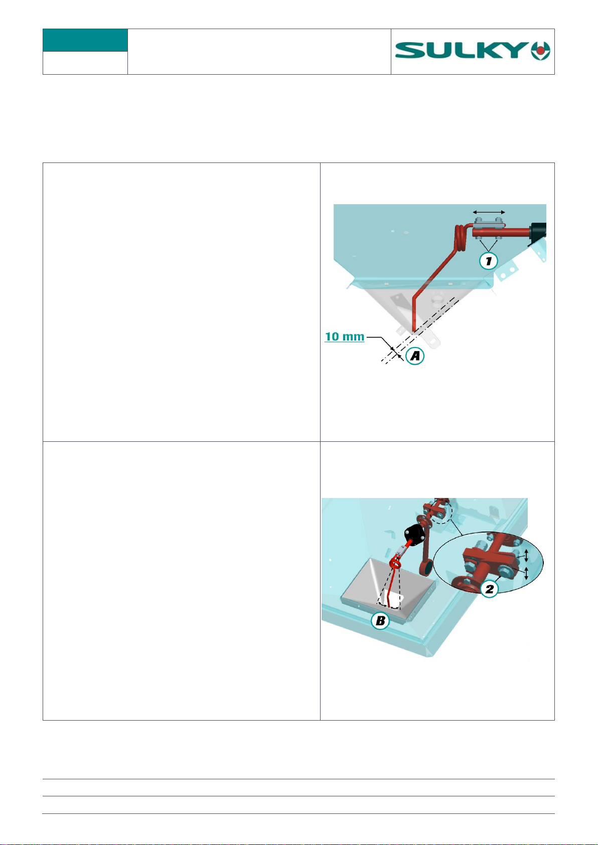
A) The space between the tip of the agitator (A) and the
shutter must be 10 mm.
This distance may not be exactly 10 mm; the most
important thing is that the two agitators have the same
dimension, for example: 12mm
To adjust the distance of an agitator tip, simply loosen
the screws ①, and move the tip on its support.
B) The agitator tip sweep must be symmetrical in relation
to the application rate openings.
The most important thing is that the two sides be set
identically.
To adjust the sweep, you must act on screw ②under
the hopper.
The two half shafts are fitted with a slot to allow their
adjustment.

DX - ISOBUS
MECHANICAL CALIBRATION OF THE
SHUTTERS
B2
NAME : TRAINING DEPARTMENT
DATE : 2019.09
PAGE : 9/55
RÉFÉRENCE : TECHNICIAN OPERATING MANUAL DX ISOBUS
IND 01
Empty spreader, shutters open, and electrical application rate actuators disconnect from lever
Remove the flow reducers if they are mounted
Place a Ø 34 mm round bar in the shutter opening ①.
Then close using the lever until the shutter comes into contact with the Ø 34 mm rod. Under these
conditions the index of the application rate lever ② must be at mark 35.
If this is not the case, the index is mounted on slot ③, and therefore it must be moved in front of mark 35.
If necessary, fit back flow reducers and rate actuators
ROD Ø34 MM
35

DX - ISOBUS
CALIBRATION OF APPLICATION
RATE ACTUATORS
B3
NAME : TRAINING DEPARTMENT
DATE : 2019.09
PAGE : 10/55
RÉFÉRENCE : TECHNICIAN OPERATING MANUAL DX ISOBUS
IND 01
First make sure the mechanical calibrations of the shutters to mark 35.
Shutter calibration, see Sheet B2
On the universal terminal, access the menu
ADVANCED SETTINGS
Select Actuators & Sensors
Enter the PIN code 1936 and confirm.
Using display the page Actuator Setup
Press
The terminal is displayed : Actuators Adjusted
Application rate electric actuators :
The index of the application rate levers must be on mark 35
If this is not the case, the lower attachments of the actuators must be adjusted (presence of adjustment
slots).
- At the minimum travel of the actuator (rod retracted) the application rate cursor is located at 12.5 ± 1.
- At the maximum travel, the application rate cursor is located at 83.5 ±1.
35

DX - ISOBUS
SHUTTER GUIDE SETTINGS
B4
NAME : TRAINING DEPARTMENT
DATE : 2019.09
PAGE : 11/55
RÉFÉRENCE : TECHNICIAN OPERATING MANUAL DX ISOBUS
IND 01
When the shutter guide ①is too tight, it can cause blocking of the shutter during its hydraulic opening
before it comes to a stop with control ②. In this case, you must free up a gap with screws ③. Check with the
spreader under load, and leave a gap of approximately 1 mm between the bowl and the shutter.
For easier access to the upper screw, it is advisable to remove the disc.

DX - ISOBUS
CALIBRATION OF THE
WEIGHING DEVICE
C1
NAME : TRAINING DEPARTMENT
DATE : 2019.09
PAGE : 12/55
RÉFÉRENCE : TECHNICIAN OPERATING MANUAL DX ISOBUS
IND 01
The weighing device allows a tolerance margin of 3%. If you notice a weight difference between the control
unit information and the real weight, you can calibrate the weighing device sensor. To calibrate the weighing
device sensor follow the procedure below. In order to be able to calibrate the sensor, load a known weight into
the hopper. (The weight must be a minimum of 1000 kg).
The reference weight must be accurate in order to obtain a good result.
On the universal terminal, access the ADVANCED
SETTINGS menu
Select Weight calibration
Enter the PIN code 1234 and confirm.
Enter the Actual Weight and select the
corresponding field
The software calculates the error percentage.
Confirm the calibration with the key
Press ESC and return to the HOME page
The weighing device is calibrated

DX - ISOBUS
WEIGHING DEVICE ANGLE SENSOR
C2
NAME : TRAINING DEPARTMENT
DATE : 2019.09
PAGE : 13/55
RÉFÉRENCE : TECHNICIAN OPERATING MANUAL DX ISOBUS
IND 01
The ECU connection box has an inclinometer which continuously measures the slope of the fertilizer
spreader. This measurement enables the weighing device to be corrected depending on the angle of the
machine.
An incorrect calibration distorts the display of the weight.
Angle sensor calibration
Position the spreader perfectly level both front/rear and
left/right
On the universal terminal, access the ADVANCED
SETTINGS menu
Select Actuators & Sensors
Enter the PIN code 1936 and confirm.
Using display the page Angle sensor
Once the spreader is level press the key
The values should become 0°

DX - ISOBUS
WEIGHING BLADES CHECK
C3
NAME : TRAINING DEPARTMENT
DATE : 2019.09
PAGE : 14/55
RÉFÉRENCE : TECHNICIAN OPERATING MANUAL DX ISOBUS
IND 01
If the weight displayed on the console for a similar weight is highly random, you must check that there is
no friction or foreign bodies between the weighing device frame and the spreader chassis.
If there is friction on the frame, the tightening of the screws and the condition of the spring blades must
be checked. Screws are tightened to 18 daN.m.

DX - ISOBUS
REPLACEMENT
OF THE WEIGHING BLADES
C4.1
NAME : TRAINING DEPARTMENT
DATE : 2019.09
PAGE : 15/55
RÉFÉRENCE : TECHNICIAN OPERATING MANUAL DX ISOBUS
IND 01
It is essential for the spreader to be unhitched and on its stands.
It is recommended that you have a socket for size 14 hexagon socket screws (e.g. reference STM.14)
1- Place a nut on the pressure screw to compress the
pre-tensioning spring.
2- Remove the strain gauge
3- Remove the 2 safety stops
4- Unscrew the 16 x 65 stainless steel screws on the
triangle side
5- Remove the triangle.
The weight of the triangle is 90 kg. Provide
appropriate handling equipment
6- Remove the blades on the sides of the spreader

DX - ISOBUS
REPLACEMENT
OF THE WEIGHING BLADES
C4.2
NAME : TRAINING DEPARTMENT
DATE : 2019.09
PAGE : 16/55
RÉFÉRENCE : TECHNICIAN OPERATING MANUAL DX ISOBUS
IND 01
Assembling double blades.
For the complete replacement of the weighing
blades, you must order: 4 kits, 011013
Every kit consists of: 4 HSHC screws, 16 x 65, 4
locknuts, 4 x M16 washers, 4 x W16 stainless steel
washers, and 2 spring blades.
7- Replace the new blades on the side of the spreader
but do not tighten them
8- Caution:
At the upper level, on the spreader side. There is a
shim only under the spring blades.
(There are no shims between the top of the blades
and the support
9- Place the triangle and put the screws back without tightening them.
10-Centre the triangle so there is no friction and secure the screws to 18 daN.m.
11-Put the safety stops back-
12-Put the weight indicator into position, and centre it
under the clamping screw and tighten the 2 screws.
13-Remove the nut on the pressure screw.
14-Check the dimension of the spring on the pressure screw: 67 to 71 mm. (See next page)
15-Perform a calibration of the weighing device. (see sheet C1)

DX - ISOBUS
PRE-TENSIONING SPRING
DIMENSION INSPECTION
C5
NAME : TRAINING DEPARTMENT
DATE : 2019.09
PAGE : 17/55
RÉFÉRENCE : TECHNICIAN OPERATING MANUAL DX ISOBUS
IND 01
An incorrect adjustment of the pre-tensioning spring may cause poor stability of the weight displayed.
(Inspection and adjustment to be performed when the spreader is unhitched)
1. Checking the dimension of the spring :
67 mm < H < 71 mm
Check that screw (A) is resting on the weight indicator
with the machine unhitched.
2. Adjusting the pre-tensioning of the spring :
If the dimension of the spring is not correct, you must adjust
the clamping screw at the weight indicator to compress or
release the spring.
a) Place a nut ①on the pressure screw to compress the
spring to height 67 < 71 mm.
b) Unscrew the cone-point set screw ②
c) Adjust clamping screw ③until it comes into contact
with the weight indicator, and the pressure screw in
contact with its support ④.
d) Tighten the cone-point set screw ②
e) Remove the nut on the pressure screw.
f) The calibration of the weight indicator is compulsory
after this operation. (See sheet C1)

DX - ISOBUS
WEIGHING DEVICE SENSOR
C6.1
NAME : TRAINING DEPARTMENT
DATE : 2019.09
PAGE : 18/55
RÉFÉRENCE : TECHNICIAN OPERATING MANUAL DX ISOBUS
IND 01
1. Characteristics of the weighing device sensor :
The weight information is obtained from a strain gauge.
Weighing sensor Reference : 083920
2. Checking the supply voltage :
The ECU supplies a stabilized voltage of 5.00 Volts to the
weight indicator, and it measures its output voltage based
on the load.
Check the voltage between the terminals of the brown wire
and the blue wire.
WIRE COLOUR
FUNCTION
BROWN
+5V
BLUE
0V
YELLOW-GREEN
+VSIGNAL (MV)
BLACK
0VSIGNAL
GREY
SCREEN
3. Weighing device settings :
On the universal terminal, access the ADVANCED
SETTINGS menu
Select Actuators & Sensors
Enter the PIN code 1936 and confirm.
Using display the Weigh Cell page.
Tare point and High point are the
weighing device calibration values.
In case of a malfunction of the weighing device, these values must be checked :
Tare point between 0.5 and 2 High point between 1050 and 1300.
If the values are outside these limits, enter the average values :
Tare point Load zero : 0.86 High point : 1260.00
It is then necessary to perform a calibration of the weighing device (see sheet C1) to restore the accuracy

DX - ISOBUS
WEIGHING DEVICE SENSOR
C6.2
NAME : TRAINING DEPARTMENT
DATE : 2019.09
PAGE : 19/55
RÉFÉRENCE : TECHNICIAN OPERATING MANUAL DX ISOBUS
IND 01
4. Weighing device sensor check :
Checking the weighing device sensor is only carried out after a positive diagnosis of the link between the CAN
and ECU and a weight indicator supply voltage.
a) When checking the sensor the spreader must be
unhitched.
b) Place a nut on the pressure screw ①to
compress the spring so there is no strain on the
weighing beam.
c) Completely disconnect the weight indicator in
the connection box ②and uncouple the grey
wire from the blue wire
d) Check the values opposite. The weighing device
sensor is considered to be compliant if it meets
all these indications.
BRAND SENSOR
VISCHAY
RBETWEEN THE BROWN
AND BLUE WIRES
385 Ω+/- 10
RBETWEEN THE GREEN/
YELLOW AND BLACK WIRES
353 Ω+/- 3
RBETWEEN THE GREY WIRE
AND EACH OF THE 4OTHER
WIRES
NO CONTINUITY

DX - ISOBUS
ELECTRICAL APPLICATION RATE
ACTUATORS
D1.1
NAME : TRAINING DEPARTMENT
DATE : 2019.09
PAGE : 20/55
RÉFÉRENCE : TECHNICIAN OPERATING MANUAL DX ISOBUS
IND 01
1. Characteristics of the application rate electric
actuators :
The adjustment of the application rate is obtained by 2
electric actuators of the type :
LINAK 121M00-1130122X STAINLESS STEEL rod
130 corresponds to the actuator travel in mm
Actuator Reference : 082501
These actuators have a 130 mm travel with limit switches
and an ILS position sensor. The ILS sensor sends 2
pulses/mm of travel.
Thus for 130 mm of travel, the actuator sends 260 pulses.
They are powered by 4 wires :
WIRE COLOUR
FUNCTION
RED
+
POWER SUPPLY
BLUE
-
WHITE
ACTUATOR
SIGNAL
ILS SENSOR
(POSITION
SENSOR)
BLACK
0VSIGNAL
2. Display of malfunction alarms :
If there is no feedback from an actuator or an actuator is
inactive, the following alarms are triggered :
Left-hand application rate actuator LEFT RATE
Right-hand application rate actuator RIGHT RATE
Table of contents
Other Sulky Burel Farm Equipment manuals
Popular Farm Equipment manuals by other brands

Big Dutchman
Big Dutchman Dry Rapid DR 1500 Mounting and operating instructions

GREAT PLAINS
GREAT PLAINS 3P1006NT Original instructions

CARLOTTI
CARLOTTI KMC Series Use and maintenance handbook

Quicke
Quicke Q 640 instruction manual

PremierOne
PremierOne 70550 operating instructions

New Holland
New Holland TH Telehandler Quick operation guide