manuals.online logo
Brands
  1. Home
  2. •
  3. Brands
  4. •
  5. Sulky
  6. •
  7. Spreader
  8. •
  9. Sulky X40+ Series User manual

Sulky X40+ Series User manual

Käyttöohje
Original Instructions
Originalbetriebsanleitung
LUE OHJEET HUOLELLISESTI ENNEN KONEEN KÄYTTÖÄ
PLEASE READ CAREFULLY BEFORE USING THE MACHINE
VOR INBETRIEBNAHME SORGFÄLTIG LESEN!
Les Portes de Bretagne
P.A. de la Gaultière – 35220 CHATEAUBOURG France
Tél :(33)02-99-00-84-84 · Fax : (33)02-99-62-39-38
Site Internet : www.sulky-burel.com
E-Mail : [email protected]om
Adresse postale
SULKY-BUREL – CS 20005 – 35538 NOYAL SUR VILAINE CEDEX France
Original Réf: 400 619 - 01 FR-EN-DE/ED
1900 - 3000
+
Ruopankatu 8
20360 Turku
Konemyynti puh. 020 7459 700
Varaosat puh. 020 7459 705
www.turunkonekeskus.fi
[email protected]
Cher Client,
Vous avez choisi notre Épandeur, et nous vous
remercions de votre con ance pour notre matériel.
Pour une bonne utilisation, et pour tirer pro t de
toutes les capacités de votre épandeur, nous vous
recommandons de lire attentivement cette notice.
De par votre expérience, n’hésitez pas à nous faire part
de vos observations et suggestions, toujours utiles pour
l’amélioration de nos produits.
Nous vous saurions gré de nous retourner le bon de
Garantie dûment rempli.
En vous souhaitant bon usage de votre épandeur
d’engrais,
Veuillez agréer, Cher Client, l’assurance de nos meilleurs
sentiments.
J. BUREL
Président
1
J. BUREL
Puheenjohtaja
Arvoisa asiakas / Dear Customer / Geehrter Kunde
FI
Dear Customer,
Thank you for trusting our equipment and
choosing the spreader.
To ensure correct operation, and to get the
most out of your spreader, we recommend
that you read these instructions carefully.
Please do not hesitate to give us your
suggestions and comments based on your
experience. They are always useful for
improving our products.
We would be grateful if you could return
the duly completed guarantee coupon.
We hope your fertilizer spreader will
provide long and trouble-free service.
Yours sincerely.
J. BUREL
Chairman
EN
Arvoisa Asiakas,
Kiitämme Sinua luottamuksesta
koneisiimme ja lannoitteen levittimen
valinnasta.
Suosittelemme tämän ohjekirjan
huolellista lukemista levittimen oikean
käytön varmistamiseksi ja hyötyäksesi
täydellisesti sen suorituskyvyistä.
Vastaanotamme mielellämme
kokemuksiisi perustuvaa palautetta,
josta on aina hyötyä tuotteidemme
laadun kehittämisessä.
Pyydämme Sinua täyttämään ja
palauttamaan takuutodistuksen.
Toivotamme Sinulle lannoitteen
levittimen pitkäaikaista ja ongelmatonta
käyttöä.
Kunnioittavasti.
22
DIE MASCHINE ENTSPRICHT ALLEN
EINSCHLÄGIGEN BESTIMMUNGEN DER
MASCHINENRICHTLINIE 2006/42/EG
DIE MASCHINE ENTSPRICHT
DEN BESTIMMUNGEN
DER NACHFOLGENDEN RICHTLINIEN:
EMV-RICHTLINIE 2004/108/EG
THE MACHINE CONFORMS TO THE
RELEVANT TERMS OF THE EUROPEAN
MACHINERY DIRECTIVE 2006/42/EC.
THE MACHINE ALSO CONFORMS TO THE TERMS OF THE
FOLLOWING DIRECTIVES :
DIRECTIVE EMC 2004/108/EC
SULKY-BUREL
PA DE LA GAULTIÈRE
35220 CHATEAUBOURG FRANCE
Julien BUREL
PA DE LA GAULTIÈRE
35220 CHATEAUBOURG FRANCE
DISTRIBUTEUR D’ENGRAIS
SPREADER
DÜNGERSTREUER
X40+
ALLEKIRJOITUS: :
SIGNED:
UNTERZEICHNET:
J. BUREL
PRÉSIDENT
CHAIRMAN
PRÄSIDENT
FI EN DE
Selon annexe 2, partie 1, point A de la directive « machines » 2006/42/CE.
In accordance with Appendix 2, Section 1, Point A of the European Machinery Directive 2006/42/EC.
Gemäß Anhang II, Teil 1, Abschnitt A der Maschinenrichtlinie 2006/42/EG.
Vaatimustenmukaisuustodistus
Declaration of Conformity
Konformitätserklärung
VALMISTAJAN NIMI JA OSOITE :
MANUFACTURER’SNAME AND ADDRESS:
NAME UND ADRESSE DES HERSTELLERS:
TEKNISTEN DOKUMENTTIEN HYVÄKSYMISEEN VALTUUTETUN
HENKILÖN NIMI JA OSOITE :
NAME AND ADDRESS OF THE PERSON AUTHORISED
TO COMPILE THE TECHNICAL SPECIFICATIONS:
NAME UND ADRESSE DES FÜR DIE ZUSAMMENSTELLUNG
DER TECHNISCHEN UNTERLAGEN BEVOLLMÄCHTIGTEN:
KONEEN KUVAUS :
MACHINE DESCRIPTION :
BESCHREIBUNG DER MASCHINE:
TYYYPPI :
TYPE:
TYP:
LISÄVARUSTEET:
ACCESSORIES:
ZUSATZAUSRÜSTUNGEN:
LOKAKUU 2015CHÂTEAUBOURG :
CHÂTEAUBOURG: OCTOBER 2015
AUSGESTELLT IN CHÂTEAUBOURG: OKTOBER 2015
SARJANUMERO :
SERIAL NUMBER:
SERIENNUMMER:
KONE VASTAA EU KONEDIREKTIIVIN EUROPEAN
MACHINERY DIRECTIVE 2006-42 CE
ASETTAMIA VAATIMUKSIA
KONE ON MYÖS SEURAAVIEN DIREKTIIVIEN
VAATIMUSTEN MUKAINEN :
DIRECTIVE CEM 2004 / 108 / CE
3
Turva määräykset
- noudattaa käytössä, ylläpidossa ja huollossa
valmistajan antamia ohjeita
- käyttää vain alkuperäisiä tai valmistajan
suosittelemia varaosia, laitteita ja varusteita.
-noudattaa käytössä, ylläpidossa ja huollossa
valmistajan antamia ohjeita
-käyttää vain alkuperäisiä tai valmistajan
suosittelemia varaosia, laitteita ja varusteita. .
Levitintä saa käyttää, huoltaa ja korjata vain pätevä
henkilö, joka on perehtynyt koneen ominaisuuksiin,
toimintaan ja käyttöön. Näitä henkilöitä pitää myös
informoida koneen käytössä ilmenevistä
mahdollisista vaaroista. Käyttäjän tulee tiukasti
noudattaa voimassa olevia paikallisia määräyksiä:
-onnettomuuksien estäminen
-työturvallisuus (työsuojelumääräykset)
- kuljetus yleisellä tiellä (tieliikennemääräykset)
Noudata aina tarkasti koneessa olevia varoituskilpiä
ja tarroja.
Koneen omistaja on aina vastuussa kaikista ilman
valmistajan ennakolta antamaa kirjallista lupaa
koneeseen tehdyistä muutoksista ja niiden
aiheuttamista vahingoista.
- Ohjaamossa kuljettajan kohdalla mitattu
melutaso (akustinen paine) ohjaamon ovi suljettuna
on 74 dB(A).
Mittauslaite: SL 401
Mikrofooni on sijoitettu EN ISO 4254-1 Liitte B pykälä
B 2.6 mukaisesti.
-Melutaso riippuu oleellisesti käytettävästä
traktorista.
LEVITTIMEN KIINNITTÄMINEN
1 - Kun kone kiinnitetään tai irrotetaan traktorista,
aseta hydraulisen nostolaitteen hallintavipu
sellaiseen asentoon että nostolaitteen mekanismi ei
käynnisty vahingossa.
2 - Kun kone kiinnitetään traktorin nostolaitteeseen,
varmista että vetotappien tai pallojen halkaisijat
vastaavat traktorin nostolaitteen kourien mitoitusta.
3 - Varoitus! Nostolaittteen noston alueella on
murskautumisen tai repeytymisen vaara.
4 - Älä seiso koneen ja traktorin välissä tai levittimen
lähistöllä kun se nostetaan ylös.
5 - Kuljetuksen aikana nostolaitteen sivurajoittimet
pitää olla kiinnitettyina koneeseen kellunnan ja
siviliikkeen estämiseksi.
6 - Kun konetta kuljetetaan nostolaitteessa
yläasennossa, nostolaitteen hallintavipu pitää olla
lukittu.
7 - Älä koskaan irrota konetta kun säiliö on täynnä.
Vaara
Liikkuvia osia,
pysy kaukana
Varoitus Kantavuutta ei
saa ylittää
Koneen
rikkoutumisen
riski
Onnettomuuden
riski
Käytön ohje
Koneen rikkoutumisen
riski. Lue käyttöohje.
FI
Koneesta putoamisen
vaara. Älä nouse
koneen päälle.
Ⴠ Näitä symboleja käytetään tässä käyttöohjeessa aina kun annetaan ohjeet ja suositukset koskien sinun tai muiden turvallisuutta tai koneen
oikeaa käyttöä.
Ⴠ Nämä ohjeet ja suositukset pitää antaa kaikille koneen käyttäjille.
YLEISET TURVAMÄÄRÄYKSET
Aina kun traktori/kone yhdistelmää käynnistetään
ja käytetään, pitää ennakolta varmistaa että se on
voimassaolevien työturvamääräysten ja
tieliikeennesääntöjen mukainen.
YLEISTÄ
1 - Tässä käyttöohjeessa annettujen ohjeiden lisäksi
pitää aina noudattaa lain mukaisia turva-
määräyksiä ja ohjeita onnettomuuksien estämiseksi.
2 -Koneeseen kiinnitetyt varoituskilvet auttavat
onnettomuksien riskien huomioimisessa ja niiden
estämisessä.
3 -Yleisillä teillä ajettaessa pitää aina noudattaa
paikallisia liikennesääntöjä ja määräyksiä.
4 -Ennen työn aloitusta on erittäin tärkeää että
käyttäjä tutustuu koneen hallintalaitteisiin ja niiden
toimintaan. Koneen ollessa käynnissä ja työssä se
saattaa olla liian myöhäistä.
5 -Kuljettajan tulee välttää löysien vaatteiden
käyttöä, sillä ne saattavat tarttua liikkuviin osiin.
6 -Traktorin pitää olla varustettu määräysten
mukaisella turvaohjaamolla tai turvakaarilla.
7 -Ennen työn aloitusta pitää tarkastaa
työympäristön turvallisuus - varo varsinkin lapsia.
Varmista että näkyvyys ympärille on hyvä. Poista
kaikki henkilöt ja eläimet vaara-alueelta.
8 -Henkilöiden ja eläimien kuljettaminen koneella
on ehdottomasti kielletty koneen ollessa käytössä tai
paikallaan.
9 -Kone voidaan kiinnittää traktoriin vain kun se on
varustettu tarkoituksenmukaisella ja turva-
määräykset ja standardit täyttävällä vetolaitteella.
10 -Koneen kiinnityksessä traktoriin ja irrotuksessa
on oltava erittäin varovainen.
11 -Ennen koneen kiinnitystä varmista että traktorin
etuakselin paino on riittävä. Tarvittaessa on
käytettävä etupainoja traktorin valmistajan
antaminen ohjeiden mukaan.
12 -Älä ylitä sallittuja maksimi akselipainoja tai
ajoneuvon kokonaispainoa.
13 -Älä ylitä yleisellä tiellä ajossa sallittuja maksimi
mittoja.
14 -Ennen kuin ajat yleiselle tielle varmista että
sääntöjen mukaiset varoitus- ja suojalaitteet (valot,
heijastimet, hitaan ajoneuvon kolmio jne.) ovat
paikoillaan ja toimivat kunnolla. Vaihda palaneet
polttimot saman tyyppisiin ja värisiin polttimoihin.
15 - Kaikki kaukosäätölaitteet (johdot, vaijerit,
tangot, letkut jne.) pitää sijoittaa niin että ne eivät
vahingossa kytke pois tai päälle toimintoja, jotka
saattavat aiheuttaa onnettomuuden tai vahingon.
16 -Ennen tielle ajoa aseta kone kuljetusasentoon
valmistajan ohjeiden mukaisesti.
17 -Älä koskaan poistu kuljettajan istuimelta
traktorin käydessä.
18 -Ajonopeus ja koneen käyttötapa pitää aina
sovittaa maan laadun, tien ja ajoväylän mukaan.
Vältä kaikissa olosuhteissa äkillisiä käännöksiä.
19 -Ohjauksen tarkkuuteen, traktorin pitoon, tien
kantavuuteen ja jarrujen tehokkuuteen vaikuttavat
koneen paino ja vetotapa, etuakselin ominaisuudet
ja ajettavan maan ja väylän rakenne. On erittäin
tärkeää että nämä kaikki ominaisuudet otetaan
huomioon joka tilanteessa.
20 -Ole erittäin tarkka ja huomio koneyksikön
ulkonemat, pituus, korkeus ja paino.
21 -Ennen koneen käyttöä varmista että kaikki
suojat ja turvalaitteet ovat paikoillaan ja hyvässä
kunnossa. Vaurioituneet suojat pitää välittömästi
vaihtaa uusiin.
22 -Ennen koneen käyttöä tulee tarkastaa mutterien
ja pulttien tiukkuudet, erityisesti työvälineiden
kiinnitys (lautaset, rajoittimet jne.). Kiristä
tarvittaessa.
23 -Älä seiso koneen työalueella.
24 -Varoitus! Varo kaukosäädöllä, erityisesti
hydraulisesti ohjattavien laitteiden murskaavaa tai
repivää vaikutusta.
25 -Ennen kuin poistut traktorin ohjaamosta tai
ennen koneelle tehtäviä toimenpiteitä sammuta
traktorin moottori, irrota virta-avvain virtalukosta ja
odota kunnes kaikki liikkuvat osat ovat pysähtyneet.
26 -Älä seiso traktorin ja koneen välissä ennen kuin
käsijarru on kytketty ja/tai renkaiden alle on
asetettu kiilat.
27 -Aina ennen koneen käyttöä varmista että se ei
käynnisty tahattomasti.
28 -Älä käytä nostolenkkiä koneen nostamiseen kun
se on kuormattuna.
29 - Koneen kuormauksessa, säädössä, käytössä,
huollossa ja pesussa pitää käyttää henkilökohtaisia
tilanteen mukaisia suojavarusteita.
Käyttäjällä pitää olla haalarit, suojakäsineet,
suojalasit ja turvakengät ja maski. Turvavarusteiden
pitää varmistaa tehtävän mukainen suojautuminen
työssä käytettäviltä aineilta; tarkasta aineista
annetut turvamääräykset ja ohjeet.
KONEEN OIKEA KÄYTTÖ
Levintintä voidaan käyttää vain sille suunniteltuihin
ja tarkoitettuihin tehtäviin.
Vain yksi henkilö voi kerrallaan käyttää konetta.
Valmistaja ei vastaa mistään vahingoista, jotka
ovat sattuneet kun konetta on käytetty muissa kuin
valmistajan sallimissa tarkoituksissa.
Koneen käyttö muihin kuin valmistajan sallimiin
töihin ja käyttötarkoituksiin tapahtuu täysin
käyttäjän omalla riskillä.
Koneen oikeaa käyttöä on:
1
3
3
2
2
2
VAARA
4
FI
6 -Tarkasta aina että nivelakselit on kiinnitetty ja
lukittu kunnolla..
7 -Varmista aina että nivelakselin suojat ovat
ketjuilla paikalleen kiinnitetyt niin että ne eivät
pääse pyörimään.
8 -Ennen kuin voimanotto kytketään pitää
varmistaa että VOA:n pyörimisnopeus ja suunta
ovat valmistajan antamien ohjeiden mukaiset.
9 -Varmista aina ennen VOA:n kytkemistä että
koneen lähellä ei ole ihmisiä tai eläimiä.
10 -Jos nivelakselin käyttökulma tulee lähelle
valmistajan antamaa raja-arvoa, kytke voimanotto
heti pois päältä.
11 -Varoitus! Kun voimanotto on kytketty pois
päältä liikkuvat osat saattavat hetken jatkaa
liikettään. Älä lähesty liikkuvia osia ennen kuin ne
ovat täysin pysähtyneet.
12 - Kun nivelakseli on irrotettu koneesta, pitää se
asettaa sille varattuun telineeseen.
13 -Kun nivelakseli on irrotettu traktorista VUO
akselista, pitää akselin suojus asettaa takaisin
paikalleen.
14 -Vaurioitunut nivelakseli pitää heti vaihtaa
uuteen.
HYDRAULIIKKA
1 -Varoitus! Hydrauliikkajärjestelmässä on korkea
paine.
2 -Kun asennetaan hydraulisia moottoreita tai
sylintereitä pitää varmistaa että hydrauliikkapiirit
on kytketty oikein valmistajan antamien ohjeiden
mukaan.
3 -Ennen kuin traktorin hydrauliikkajärjestelmään
kiinnitetään letku tulee varmistaa että
järjestelmässä ei ole painetta.
4 -Käyttäjän tulee tunnistaa ja varmistaa liittimien
kytkennät traktorin ja koneen välillä, jotta vältytään
vääriltä kytkennöiltä. Varoitus! Vaarana on
päinvastainen toiminto (esim. nosto/lasku).
5 -Tarkasta hydrauliikkaletkut kerran vuodessa:
. Ulkopinnan vauriot
. Ulkopinnan huokoisuus
. Muodonmuutoksen ilman painetta ja
paineistettuna
. Liittimien ja tiivisteiden kunto
Letkujen maksimi käyttöikä on 6 vuotta. Kun
letkut vaihdetaan uusiin, pitää varmistaa että ne
ovat valmistajan antamien suositusten mukaiset.
6 -Jos vuotoja havaitaan, pitää tehdä kaikki
tarvittavat toimenpiteen onnettomuuksien ja
vahinkojen välttämiseksi..
7 -Paineistettu neste, varsinkin hydrauliikkaöljy,
saattaa aiheuttaa vakavan vamman jos se pääsee
kosketukseen ihon kanssa. Vahingon tapahtuessa
hakeudu heti lääkärin hoitoon. Suuri tulehdusriski.
8 -Aina ennen hydraulikkajärjestelmän
toimenpiteitä laske kone alas, vapauta
järjestelmän paine, sammuta moottori ja irrota
virta-avain virtalukosta.
HUOLTO
1 -Ennen mitään säätö-, huolto- tai korjaustöitä tai
kun etsitään mahdollisen häriön tai vian syytä pitää
aina kytkeä voimanotto pois päältä, sammuttaa
moottori ja irrottaa virta-avain virtalukosta.
2 -Tarkasta säännöllisesti muttereiden ja pulttien
kireys. Kiristä ne tarvittaessa.
3 -Jos kone pitää nostaa ylös huoltotöiden vuoksi,
pitää se tukea huolellisesti asianmukasten tukien
avulla.
4 -Kun koneen työstäviä ja liikkuvia osia vaihdetaan
(levittimen siipi tai kylvökoneen vannas), käytä
suojakäsineitä ja käytä vain sopivia ja
tarkoituksenmukaisia työvälineitä.
5 -Ympäristön suojelemiseksi öljyjen, rasvojen tai
erilaisten suodattimen heittäminen luontoon on
kielletty. Anna nämä asiantuntevien jätelaitosten
käsiteltäviksi.
6 -Ennen sähköiseen virtapiiriin kohdistuvia
toimenpiteitä pitää virtalähde kytkeä pois päältä.
7 -Suojalaitteet ja suojukset jotka voivat kulua tai
rikkoutua pitää tarkastaa säännöllisesti. Vaihda
vialliset suojat heti uusiin.
8 -Varaosien pitää olla standardien ja valmistajan
vaatimusten mukaisia. Käytä vain valmistajan
alkuperäisiä varaosia.
9 -Aina ennen traktorissa tai työkoneessa tehtävien
hitsaustöiden aloitusta pitää irrottaa laturin ja akun
kaapelit.
10 -Puristuksen tai paineen alaisten osien
(jouset, paineakut jne.) korjaukset tulee antaa
ammattitaitoisen ja pätevän asentajan
tehtäväksi sopivia erikoistyökaluja
käyttämällä.
1
Pyörivä sekoitin
2
Pyörivä lautanen
Sinkoutuva, lentävä lannoite
3
Murskautumisen tai viillon riski
KÄYTTÖLAITTEET
(Voimanotto ja nivelakselit)
1 -Käytä vain koneen mukana toimitettua tai
valmistajan suosittelemaa nivelakselia.
2 -Voimanottoakselin ja nivelakselin suojusten pitää
olla aina paikoillaan ja hyvässä kunnossa.
3 -Varmista että nivelakselin suojaputket on
kunnossa ja kunnolla paikoillaan sekä työ- että
kuljetusasennossa.
4 -Ennen kuin asennat tai irrotat nivelakselin kytke
voimanotto pois päältä, sammuta moottori ja irrota
virta-avain virtalukosta.
5 -Jos nivelakseli on varustettu ylikuormakytkimellä
tai vapaakytkimellä nämä pitää olla asennetuna
koneen käyttöakselin puolelle.
GENERAL SAFETY REGULATIONS
Every time the tractor/machine assembly is to be
started up and used, you should ensure beforehand
that it complies with current legislation on safety at
work and Road Tra c regulations.
GENERAL
1 - In addition to the instructions contained in this
manual, legislation relating to safety instructions
and accident prevention should be complied with.
2 - Warnings a xed to the machine give indications
regarding safety measures to be observed and help
to avoid accidents.
3 - When travelling on public roads, abide by the
provisions of the Highway Code.
4 - Before starting work, it is essential that the user
familiarizes himself with the control and operating
elements of the machine and their respective
functions. When the machine is running, it may be
too late.
5 - The user should avoid wearing loose clothing
which may be caught up in the moving parts.
6 - We recommend using a tractor with a safety cab
or roll bar conforming to standards in force.
7 - Before starting up the machine and beginning
work, check the immediate surroundings,
particularly for children. Make sure that visibility is
adequate. Clear any persons or animals out of the
danger zone.
8 - It is strictly forbidden to transport any persons
or animals on board the machine whether it is in
operation or not.
9 - The machine should only be coupled up to the
tractor at the specially provided towing points and in
accordance with applicable safety standards.
10 - Extreme care must be taken when coupling or
uncoupling the machine from the tractor.
11 - Before hitching up the machine, ensure that
the front axle of the tractor is su ciently weighted.
Ballast weights should be  tted to the special
supports in accordance with the instructions of the
tractor manufacturer.
12 - Do not exceed the maximum axle weight or the
gross vehicle weight rating.
13 - Do not exceed the maximum authorized
dimensions for using public roads.
14 - Before entering a public road, ensure that the
protective and signalling devices (lights, re ectors,
etc.) required by law are  tted and working properly.
Replace burnt out bulbs with the same types and
colours.
15 - All remote controls (cords, cables, rods, hoses,
etc.) must be positioned so that they cannot
accidentally set o any manoeuvre which may cause
an accident or damage.
16 - Before entering a public road, place the machine
in the transport position, in accordance with the
manufacturer’s instructions.
17 - Never leave the driver’s position whilst the
tractor is running.
18 - The speed and the method of operation must
always be adapted to the land, roads and paths.
Avoid sudden changes of direction under all
circumstances.
19 - Precision of the steering, tractor adhesion, road
holding and e ectiveness of the braking mechanism
are in uenced by factors such as the weight and
nature of the machine being towed, the front axle
stage and the state of the land or path. It is essential,
therefore, that the appropriate care is taken for each
situation.
20 - Take extra care when cornering, taking account
of the overhang, length, height and weight of the
machine or trailer being towed.
21 - Before using the machine, ensure that
all protective devices are  tted and in good
condition. Damaged protectors should be replaced
immediately.
22 - Before using the machine, check that nuts and
screws are tight, particularly those for attaching
tools (discs,  ickers, de ectors, etc.). Tighten if
necessary.
23 - Do not stand in the operating area of the
machine.
24 - Caution! Be aware of any crushing and shearing
zones on remote-controlled and particularly
hydraulically-controlled parts.
25 - Before climbing down from the tractor, or before
any operation on the machine, turn o the engine,
remove the key from the ignition and wait until all
moving parts have come to a standstill.
26 - Do not stand between the tractor and the
machine until the handbrake has been applied and/
or the wheels have been wedged.
27 - Before any operation on the machine, ensure
that it cannot be started up accidentally.
28 - Do not use the lifting ring to lift the machine
when it is loaded.
29 - When loading, adjusting, using, servicing and
washing the machine, the user should wear personal
protective equipment adapted to the products used
with the machine.
The user should be protected by wearing an overall,
gloves, glasses and safety shoes and a mask. Such
protective equipment should ensure a level of
protection suited to the products used with the
machine; refer to the safety regulations of the
products used.
PROPER USE OF THE MACHINE
The Spreader must only be used for tasks for which it
has been designed.
The manufacturer will not be liable for any damage
caused by using the machine for applications other
than those speci ed by the manufacturer.
Using the machine for purposes other than those
originally intended will be done so entirely at the
user’s risk.
Proper use of the machine also implies:
- complying with instructions on use, care and
maintenance provided by the manufacturer;
- using only original or manufacturer recommended
spare parts, equipment and accessories.
The Spreader must only be operated, maintained
and repaired by competent persons, familiar with
the speci cations and methods of operation of the
machine. These persons must also be informed of the
dangers to which they may be exposed.
The user must strictly abide by current legislation
regarding:
- accident prevention;
- safety at work (Health and Safety Regulations);
- transport on public roads (Road Tra c
Regulations).
Strict compliance with warnings a xed to the
machine is obligatory.
The owner of the equipment shall become liable for
any damage resulting from alterations made to the
machine by the user or any other person, without the
prior written consent of the manufacturer.
- The noise emission value measured at the driving
position with the cab closed (level of acoustic
pressure) is 74 dB(A).
Measuring device: SL 401
Position of the microphone placed in accordance
with Paragraph B 2.6 of Appendix B of NF EN ISO
4254-1.
This level of acoustic pressure essentially depends on
the tractor used.
HITCHING
1 - When hitching or unhitching the machine from
the tractor, place the control lever of the hydraulic lift
in such a position that the lifting mechanism cannot
be activated accidentally.
2 - When hitching the machine to the three-point
lifting mechanism of the tractor, ensure that the
diameters of the pins or gudgeons correspond to the
diameter of the tractor ball joints.
3 - Caution! In the three-point lifting zone, there may
be a danger of crushing and shearing.
4 - Do not stand between the tractor and the
machine whilst operating the external lift control
lever.
5 - When in transport, lifting mechanism stabilizer
bars must be  tted to the machine to avoid  oating
and side movement.
6 - When transporting the machine in the raised
position, lock the lift control lever.
7 - Never unhitch the machine when the hopper is
full.
DRIVE EQUIPMENT
(Power take-o and universal drive shafts)
1 - Only use universal drive shafts supplied with the
Ⴠ These symbols are used in these instructions every time recommendations are provided concerning your safety, the safety of others or the correct
operation of the machine.
Ⴠ These recommendations must be given to all users of the machine.
EN
Fall hazard.
Do not climb on
the machine.
Danger
Moving parts,
keep away
Caution Payload should
not be exceeded
Risk of damage
to the machine
Risk of accident Operating tip
Risk of damage
to the machine
Consult the
instruction lea et
Safety regulations
5
1
3
3
2
2
2
EN
machine or recommended by the manufacturer.
2 - Power take-o and universal drive shaft guards
must always be  tted and in good condition.
3 - Ensure that the tubes of the universal drive shafts
are properly guarded, both in the working position
and in the transport position.
4 - Before connecting or disconnecting a universal
drive shaft, disengage the power take-o , turn o
the engine and re-move the key from the ignition.
5 - If the primary universal drive shaft is  tted with
a torque limiter or a free wheel, these must be
mounted on the machine power take-o .
6 - Always ensure that universal drive shafts are
 tted and locked correctly.
7 - Always ensure that universal drive shaft guards
are immobilized in rotation using the specially
provided chains.
8 - Before engaging power take-o , ensure that
the speed selected and the direction of rotation of
the power take-o comply with the manufacturer’s
instructions.
9 - Before engaging power take-o , ensure that no
persons or animals are close to the machine.
10 - Disengage power take-o when the
universal drive shaft angle limits laid down by the
manufacturer are in danger of being exceeded.
11 - Caution! When power take-o has been
disengaged, moving parts may continue to rotate
for a few moments. Do not approach until they have
reached a complete standstill.
12 - On removal from the machine, rest the universal
drive shafts on the specially provided supports.
13 - After disconnecting the universal drive shafts
from the power take-o , the protective cap should be
 tted to the power take-o .
14 - Damaged power take-o and universal drive
shaft guards must be replaced immediately.
HYDRAULIC CIRCUIT
1 - Caution! The hydraulic circuit is pressurized.
2 - When  tting hydraulic motors or cylinders,
ensure that the circuits are connected correctly in
accordance with the manufacturer’s guidelines.
3 - Before  tting a hose to the tractor’s hydraulic
circuit, ensure that the tractor-side and machine-side
circuits are not pressurized.
4 - The user of the machine is strongly recommended
to identify the hydraulic couplings between the
tractor and the machine in order to avoid wrong
connection. Caution! There is a danger of reversing
the functions (for example: raise/lower).
5 - Check hydraulic hoses once a year:
. Damage to the outer surface
. Porosity of the outer surface
. Deformation with and without pressure
. State of the  ttings and seals
The maximum working life for hoses is 6 years.
When replacing them, ensure that only hoses with
the speci cations and grade recommended by the
machine manufacturer are used.
6 - When a leak is found, all necessary precautions
should be taken to avoid accidents.
7 - Pressurized liquid, particularly hydraulic circuit
oil, may cause serious injury if it comes into contact
with the skin. If the case of injury, consult a doctor
immediately. There is a risk of infection.
8 - Before any operation on the hydraulic circuit,
lower the machine, release the pressure from the
circuit, turn o the engine and remove the key from
the ignition.
MAINTENANCE
1 - Before commencing any maintenance, servicing
or repair work, or before attempting to locate the
source of a breakdown or fault, it is essential that the
power take-o is disengaged, the engine turned o
and the key removed from the ignition.
2 - Check regularly that nuts and screws are not
loose. Tighten if necessary.
3 - Before carrying out maintenance work on a
raised machine, prop it up using appropriate means
of support.
4 - When replacing a working part (fertilizer spreader
blade or seed drill coulter), wear protective gloves
and only use appropriate tools.
5 - To protect the environment, it is forbidden to
throw away oil, grease or  lters of any kind. Give
them to specialist recycling  rms.
6 - Before operating on the electric circuit, disconnect
the power source.
7 - Protective devices likely to be exposed to wear
and tear should be checked regularly. Replace them
immediately if they are damaged.
8 - Spare parts should comply with the standards
and speci cations de ned by the manufacturer.
Only use the manufacturer’s original parts.
9 - Before commencing any electric welding work
on the tractor or the towed machine, disconnect the
alternator and battery cables.
10 - Repairs a ecting parts under stress or pressure
(springs, pressure accumulators, etc.) should be
carried out by suitably quali ed engineers with
special tools.
DANGER
1
Rotating agitator
2
Rotating disc
Projection of fertilizer
3
Risk of pinching or
crushing
6
ALLGEMEINE SICHERHEITSVORSCHRIFTEN
Vor jeder Benutzung und Inbetriebsetzung der
Schlepper-Maschine-Einheit kontrollieren, ob sie
den Sicherheitsvorschriften und den Vorschriften der
Straßenverkehrsordnung entsprechen.
ALLGEMEINES
1 - Zusätzlich zu den in diesem
Handbuch enthaltenen Anweisungen die
Gesetzgebung bezüglich der Sicherheits- und
Unfallverhütungvorschriften einhalten.
2 - Die auf der Maschine angebrachten
Warnungen informieren über die einzuhaltenden
Sicherheitsmaßnahmen und tragen zur
Unfallverhütung bei.
3 - Im Straßenverkehr die Straßenverkehrsordnung
einhalten.
4 - Vor Arbeitsbeginn muß sich der
Benutzer unbedingt mit den Antriebs- und
Bedienungsorganen der Maschine und ihren
jeweiligen Funktionen vertraut machen. Während
der Arbeit ist es dafür zu spät.
5 - Weite Kleidungsstücke, die in sich bewegende
Teile geraten könnten, vermeiden.
6 - Es emp ehlt sich, gemäß den gültigen
Normen einen Schlepper mit Kabine oder
Sicherheitsverstärkung zu verwenden.
7 - Vor Inbetriebsetzung und Arbeitsbeginn die
direkte Umgebung kontrollieren (Kind !). Für
ausreichende Sicht sorgen! Personen oder Tiere
aus dem Maschinengefahrenbereich entfernen
(Schutzvorrichtungen !).
8 - Der Transport von Personen oder Tieren auf der
Maschine ist während der Arbeit oder beim Fahren
streng verboten.
9 - Die Maschine darf gemäß den geltenden
Sicherheitsnormen nur an den dafür vorgesehenen
Kupplungspunkten angehängt werden.
10 - Besondere Vorsicht ist beim An- und Abbau der
Maschine am Schlepper geboten.
11 - Vor Anhängen der Maschine kontrollieren,
ob der Ballast des Schleppers genügt. Die
Ballastelemente müssen gemäß den Vorschriften
des Schlepperherstellers auf den dafür vorgesehenen
Haltern angebracht werden.
12 - Die maximale Achslast und das zulässige
Gesamtgewicht einhalten.
13 - Das für den Straßenverkehr maximal zulässige
Außenmaß einhalten.
14 - Vor Straßenbenutzung die Schutzvorrichtungen
und Signalisierungsvorrichtungen (Licht- und
Rückstrahlelemente) anbringen und ihre Funktion
prüfen. Die defekten Glühbirnen durch Modelle
identischer Art und Farbe ersetzen.
15 - Alle Fernsteuerungen (Seil, Kabel, Stange,
Schlauch) müssen so positioniert sein, daß sie nicht
ungewollt betätigt werden und dadurch Unfälle oder
Schäden hervorrufen können.
16 - Vor Benutzung der Straße die Maschine gemäß
Herstelleranweisungen in Transportstellung bringen.
17 -. Fahrersitz nie bei laufender Maschine verlassen.
18 - Fahrgeschwindigkeit und -weise müssen immer
dem Gelände, den Straßen und Wegen angepaßt
sein. Auf alle Fälle plötzliche Richtungsänderungen
vermeiden.
19 - Die Präzision der Lenkung, die Bodenhaftung
des Schleppers, die Straßenlage und die Wirksamkeit
der Bremsvorrichtungen werden beein ußt von
Faktoren wie: Gewicht und Art der angebauten
Maschine, Belastung der Vorderachse, Zustand des
Geländes oder der Fahrbahn. Die den Bedingungen
entsprechenden Vorsichtsmaßnahmen einhalten.
20 - Besondere Vorsicht ist in Kurven geboten.
Schwerpunktlage, Länge, Höhe und Gewicht der
Maschine oder des Anhängers berücksichtigen.
21 - Vor jeder Benutzung der Maschine kontrollieren,
ob alle Schutzvorrichtungen angebracht und in
gutem Zustand sind. Bei Beschädigung sofort
austauschen.
22 - Vor jeder Benutzung kontrollieren, ob alle
Schrauben und Muttern fest angezogen sind,
insbesondere die, mit denen die Geräte befestigt sind
(Scheiben, Paletten, Schirme...). Notfalls anziehen.
23 - Sich nicht im Manövrierbereich der Maschine
aufhalten.
24 - Vorsicht! Auf den Fernsteuerungsorganen,
insbesondere auf denen mit hydraulischem
Regelkreis, kann es Stauch- und Abscherzonen
geben.
25 - Vor Verlassen des Schleppers oder vor jedem
Eingri auf der Maschine Motor abschalten,
Zündschlüssel abziehen und völligen Stillstand aller
bewegten Teile abwarten.
26 - Sich nicht zwischen Schlepper und Maschine
aufhalten, ohne zuvor die Parkbremse angezogen
und/oder Keile unter die Räder gelegt zu haben.
27 - Vor jedem Eingri an der Maschine
kontrollieren, ob diese nicht ungewollt in Betrieb
gesetzt werden kann.
29 - Während der Beladung, Einstellung, Nutzung,
Wartung und Reinigung der Maschine muss der
Benutzer eine persönliche Schutzausrüstung
tragen, die auf die Produkte abgestimmt ist, die in
Verbindung mit der Maschine verwendet werden.
Um sich zu schützen, muss der Benutzer einen Anzug,
Handschuhe, eine Schutzbrille, Sicherheitsschuhe
und eine Schutzmaske tragen. Das Schutzniveau
dieser Schutzausrüstung muss auf die in Verbindung
mit der Maschine verwendeten Produkte
abgestimmt sein. Die Sicherheitsvorschriften der
verwendeten Produkte sind zu beachten.
BESTIMMUNGSGEMÄSSE VERWENDUNG DER
MASCHINE
Der Rotorstreuer darf nur für die Arbeiten eingesetzt
werden, für die sie geplant ist.
Bei Beschädigung der Maschine infolge einer nicht
vom Hersteller spezi zierten Benutzung ist dieser
nicht haftbar.
Jede nicht der ursprünglichen Bestimmung der
Maschine entsprechende Benutzung erfolgt auf
Rechnung und Gefahr des Benutzers.
Die bestimmungsgemäße Verwendung der
Maschine setzt ebenfalls voraus:
- die Einhaltung der vom Hersteller
verordneten Benutzungs-, Wartungs- und
Instandsetzungsvorschriften,
- die ausschließliche Verwendung von
Originalersatzteilen, Originalausrüstungen und
Originalzubehör oder von Teilen, die vom Hersteller
empfohlen sind.
Der Rotorstreuer darf nur von kompetenten, mit den
technischen Daten und Benutzungsanweisungen
der Maschine vertrauten Personen benutzt, gewartet
und repariert werden, die über die Risiken informiert
sind, denen sie ausgesetzt sein könnten.
Streng die gültige Reglementierung einhalten
bezüglich:
- der Unfallverhütung,
- der Arbeitssicherheit (Arbeitsgesetzbuch)
- des Straßenverkehrs (Straßenverkehrsordnung).
Die auf der Maschine angebrachten Warnungen
berücksichtigen.
Der Hersteller haftet nicht für Schäden, die durch
Abänderungen entstehen, die vom Benutzer selbst
oder von Dritten ohne schriftliche Genehmigung an
der Maschine vorgenommen wurden.
- Der am Fahrersitz bei geschlossener
Kabine gemessene Geräuschemissionswert
(Schalldruckpegel) beträgt 74 dB(A).
Messgerät: SL 401
Position Mikrofons nach Absatz B.2.6 Anhang B der
Norm EN ISO 4254-1.
Dieser Schalldruckpegel ist im Wesentlichen vom
verwendeten Schleppertyp abhängig.
ANHÄNGUNG
1 - Beim An- und Abkuppeln der Maschine am
Schlepper, den Steuerhebel des Hydraulikkrafthebers
so stellen, daß der Hub-vorgang nicht unerwartet
ausgelöst werden kann.
2 - Beim Anhängen der Maschine am
Dreipunktkraftheber des Schleppers darauf
achten, daß die Spindel- oder Zapfendurchmesser
dem Durchmesser der Schlepperkugelgelenke
entsprechen.
3 - Vorsicht! Im Dreipunkt-Hubbereich bestehen
Stauch- und Abscherrisiken!
4 - Sich bei Betätigung des äußeren Kraftheber-
Steuerhebels nicht zwischen Schlepper und
Maschine aufhalten.
5 - Beim Transport muß die Maschine durch die
Versteifungsstreben des Krafthebers zur Vermeidung
von Unwucht und seitlicher Pendelung stabilisiert
werden.
Sicherheitsvorschriften
Ⴠ I n der Anweisung werden diese Zeichen in Verbindung mit Empfehlungen für Ihre Sicherheit und der anderer sowie die gute Funktion der Maschine
verwendet.
ჀJeder Benutzer dieser Maschine muß diese Vorschriften genau kennen..
DE
Sturzgefahr.
Nicht auf die
Maschine steigen.
Gefahr Bewegliche
Maschinenteile - sich
erst bei Stillstand
nähern
Achtung
Nutzlast niemals überschreiten
Gefahr der
Beschädigung
der Maschine
Verletzungsgefahr Hinweis zur
Erleichterung der Arbeit
Beschädigungsgefahr
Siehe Betriebsanleitung
der Maschine
7
1
3
3
2
2
2
DE
6 - Beim Transport der Maschine in angehobener
Stellung den Kraftheber-Steuerhebel blockieren.
7 - Die Maschine erst abhängen wenn der Tank leer
ist.
ANTRIEBSORGANE
(Zapfwelle und Gelenkwellen-Antrieb)
1 - Nur die mit der Maschine gelieferte oder vom
Konstrukteur empfohlene Gelenkwelle verwenden.
2 - Die Schutzvorrichtungen der Zapfwellen und
Gelenkwellen müssen immer angebracht und in
gutem Zustand sein.
3 - Auf die richtige Überlappung der
Gelenkwellenrohre sowohl in Arbeits- als auch in
Transportstellung achten.
4 - Vor Anschließen oder Abziehen einer Gelenkwelle
die Zapfwelle auskuppeln, den Motor abschalten
und den Zündschlüssel abziehen.
5 - Ist die Primärkardanwelle mit einem
Drehmomentbegrenzer oder einer Freilaufkupplung
ausgestattet, müssen diese unbedingt auf der
Zapfwelle der Maschine montiert sein.
6 - Immer auf die korrekte Montage und
Verriegelung der Kardanantriebe achten.
7 - Immer darauf achten, daß die
Schutzvorrichtungen der Gelenkwellen mit den dafür
vorgesehenen Ketten gegen Verdrehen gesichert
sind.
8 - Vor Kuppeln der Zapfwelle prüfen, ob die
gewählte Drehzahl und die Drehrichtung der
Zapfwelle den Vorschriften des Herstellers
entsprechen.
9 - Vor Kuppeln der Zapfwelle kontrollieren, ob sich
keine Personen oder Tiere in Nähe der Maschine
be nden.
10 - Die Zapfwelle auskuppeln, wenn Gefahr besteht,
daß die vom Hersteller vorgeschriebenen Grenzen
des Gelenkwellenwinkels überschritten werden.
11 - Vorsicht! Nach Auskuppeln der Zapfwelle
können Teile der Maschine noch einige Zeit
nachlaufen. Sich ihnen nie vor völligem Stillstand
nähern.
12 - Bei Abbau der Maschine die Gelenkwellen auf
den dafür vorgesehenen Haltern ablegen.
13 - Nach Abziehen der Gelenkwelle von der
Schlepperzapfwelle muß diese mit ihrer Schutzkappe
bedeckt werden.
14 - Schadhafte Schutzvorrichtungen der Zapfwelle
und der Gelenkwelle müssen sofort ausgewechselt
werden.
HYDRAULIKLEITUNG
1 - Vorsicht! Die Hydraulikleitung steht unter Druck.
2 - Bei Montage von Zylindern oder
Hydraulikmotoren auf den korrekten Anschluß
gemäß Anweisungen des Herstellers achten.
3 - Vor Anschluß eines Schlauches an der
Hydraulikleitung des Schleppers dafür sorgen, daß
die schlepper- und maschinenseitigen Leitungen
nicht unter Druck stehen.
4 - Dem Benutzer der Maschine wird zur Vermeidung
falscher Anschlüsse dringend geraten, die
Kennzeichnungen auf den Hydraulikanschlüssen
zwischen Schlepper und Maschine zu beachten, da
sonst die Gefahr einer Funktionsumkehrung besteht.
(z.B.: Heben/Senken).
5 - Einmal im Jahr die Hydraulikschläuche
kontrollieren auf:
. Beschädigung der Außenschicht
. Porosität der Außenschicht
. Verformung ohne Druck und unter Druck
. Zustand der Verbindungen und Dichtungen.
Die maximale Benutzungsdauer der Schläuche
ist 6 Jahre. Beim Auswechseln darauf achten,
daß nur Schläuche verwendet werden, deren
Eigenschaften und Qualität den Vorschriften des
Maschinenkonstrukteurs entsprechen.
6 - Bei Feststellung einer undichten Stelle alle
Vorsichtsmaßnahmen zur Unfallverhütung tre en.
7 - Eine unter Druck stehende Flüssigkeit,
insbesondere das Öl der Hydraulikleitung, kann
die Haut durchdringen und schwere Verletzungen
verursachen! Bei Verletzungen sofort Arzt
konsultieren; Infektionsgefahr!
8 - Vor jedem Eingri in die Hydraulikanlage
Maschine ablassen, Anlage drucklos schalten, Motor
abstellen und Zündschlüssel abziehen.
WARTUNG
1 - Vor Instandsetzungs-, Wartungs- oder
Reparaturarbeiten sowie bei Ermitteln einer Pannen-
oder Betriebsstörungsquelle muß die Zapfwelle
ausgekuppelt, der Motor abgeschaltet und der
Zündschlüssel abgezogen sein.
2 - Regelmäßig kontrollieren, ob Schrauben und
Muttern fest angezogen sind. Notfalls anziehen.
3 - Vor Wartung einer Maschine in angehobener
Stellung diese mit einem geeigneten Mittel
abstützen.
4 - Beim Austausch eines Funktionsteiles (Schaufel
bei Streuern oder Schare bei Drillmaschinen)
Schutzhand-
schuhe tragen und nur geeignete Werkzeuge
benutzen.
5 - Zum Schutz der Umwelt ist es verboten, Öl, Fett
und Filter jeder Art wegzuwerfen oder auszugießen.
Sie sind von darauf spezialisierten Unternehmen zu
entsorgen.
6 - Vor Eingri an der elektrischen Leitung die
Stromzufuhr unterbrechen.
7 - Verschleiß ausgesetzte Schutzvorrichtungen
müssen regelmäßig kontrolliert werden. Sie sofort
austauschen, wenn schadhaft.
8 - Die Ersatzteile müssen den Normen und
den vom Hersteller vorgegebenen technischen
Vorgaben entsprechen. Benutzen Sie ausschließlich
Originalersatzteile.
9 - Vor Elektroschweißarbeiten am Schlepper
oder der angehängten Maschine die Kabel des
Wechselstromgenerators und der Batterie abziehen.
10 - Reparaturen an Organen, die unter Spannung
oder Druck stehen (Federn, Druckspeicher, usw...)
setzen eine ausreichende Quali kation voraus und
erfordern Werkzeuge; sie dürfen daher nur von
quali ziertem Personal durchgeführt werden.
GEFAHR
1
Rührwerk in Bewegung
2
Scheibe in Bewegung
Düngerauswurf
3
Stauchgefahr Kupplung
8
99
2
3
4
5
9
1
Sivu
Sivu
Sivu
Sivu
Sivu
12-13
12-13
16-17
20-21
22-25
Käyttö
Käsittely
Traktorin tiedot
Koneen kiinnittäminen
Voimanotto
40-47
48-55
56-69
70-75
76-79
• A
• B
• C
• D
• E
Virtauksen asetus
Leveyden asetus
Leveyden tarkastukset
Reunalevityksen asetus
Ympäristönsuojelun optimointi ja
reunalevitys Tribord'lla
82-83
84-85
86-87
88-91
• A
• B
• C
• D
Peseminen
Voitelu
Tarkastukset
Kalibroinnin tarkastus
92-93
94-95
96-97
96-97
96-97
• A
• B
• C
• D
• E
Tiivistymisen eston levy
Säiliön kansi
W VISION ohjausyksikkö
W ISOBUSohjausyksikkö
“Télé-space” nivelakseli
102
103
103
• A
• B
• C
Tarrat
Tunnistaminen
Tekniset tiedot
26-37
38-39
38-39
• F
• G
• H
Ohjauslaitteiden liittäminen
Kuormaus
Tyhjennys
80-81 • F Reunalevitys Ecobord siivellä
98-99
98-99
98-99
98-99
100-101
100-101
• F
• G
• H
• I
• J
• K
Tukipyörät
Lokasuojat
Askelma
Lisälaidat
Turvapuomi
Tukien asennus
KÄYTTÖÖNOTTO
ASETUKSET
HUOLTO
LISÄVARUSTEIDEN ASENNUS
OMINAISUUDET
Suomi SISÄLLYSLUETTELO
• A
• B
• C
• D
• E
Lue käyttöohje huolellisesti ennen käyttöä. Ohjeiden ymmärtäminen parantaa
levitystä ja turvallisuutta. Suomenkieliset ohjeet seuraa symbolia : FI
10
Pages
Pages
Pages
Pages
Pages
Read the manual carefully before use. Better understanding means better and
safer spreading. For English follow the symbol.
EN
12-13
12-13
16-17
20-21
22-25
• A
• B
• C
• D
• E
Use
Handling
Tractor control
Hitching gear
Drive assembly
40-47
48-55
56-69
70-75
76-79
• A
• B
• C
• D
• E
Setting the fl w rate
Setting the width
Checking the width
Border setting with the tribord
Environmental border
optimising with the tribord
82-83
84-85
86-87
88-91
• A
• B
• C
• D
Washing
Greasing
Checks
Calibration check
92-93
94-95
96-97
96-97
96-97
• A
• B
• C
• D
• E
Anti-compaction baff
Hopper cover
W VISION control kit
W ISOBUS control kit
“Télé-space” universal joint
102
103
103
• A
• B
• C
Adhesive labels
Identifi ation
Technical Specifi ations
26-37
38-39
38-39
• F
• G
• H
Control connections
Loading
Emptying
80-81 • F Border setting with the
ecobord vane
98-99
98-99
98-99
98-99
100-101
100-101
• F
• G
• H
• I
• J
• K
Parking wheel
Mud guard
Rung
Hopper extension
Safety bar
Fitting the supports
START-UP
SETTINGS
MAINTENANCE
FITTING THE ACCESSORIES
SPECIFICATIONS
English CONTENTS
11
1
2
3
4
5
11
Seite
Seite
Seite
Seite
Seite
Deutsch VERZEICHNIS
Anweisung vor Benutzung sorgfältig durchlesen. Die Düngerstreuer verstehen,
heißt sie besser benutzen. Die deutsche Fassung ist mit gekennzeichnet.
DE
12-13
12-13
18-19
20-21
22-25
• A
• B
• C
• D
• E
Benutzung
Handhabung
Schleppersteuerung
Anbau
Antrieb
40-47
48-55
56-69
70-75
• A
• B
• C
• D
Streumengeneinstellung
Breiteneinstellung
Arbeitsbreite uberprufung
Randzoneneinstellung mit
dem Tribord
82-83
84-85
86-87
88-91
• A
• B
• C
• D
Reinigung
Schmierung
Überprüfung
Eichungskontrolle
92-93
94-95
96-97
96-97
96-97
• A
• B
• C
• D
• E
Festdruckschutz
Abdeckplane
Steuerset W VISION
Steuerset W ISOBUS
Teleskop-Kardanwelle
“Télé-space”
102
103
103
• A
• B
• C
Aufkleber
Identifizierun
Technische Daten
26-37
38-39
38-39
• F
• G
• H
Anschluß der
Schieberbetätigung
Laden
Entleeren
76-79
80-81
• E
• F
Umweltschonende
Randzonenoptimierung mit
dem Tribord
Randzoneneinstellung mit
dem Ecobord-Blatt
98-99
98-99
98-99
98-99
100-101
100-101
• F
• G
• H
• I
• J
• K
Abstellrad
Schmutzfänger
Trittbrett
Aufsatzstück
Überrollbügel
Montage der Stützen
INBETRIEBSETZUNG
EINSTELLUNGEN
WARTUNG
MONTAGE DER AUSRÜSTUNGEN
TECHNISCHE DATEN
Maschine vorsichtig heben
und sich vergewissern, daß
sich niemand im Maschinen-
bereich aufhält.
Alle für den Transport
notwendigen Befestigungen
oder Schutzvorrichtungen
entfernen.
Take care when lifting the
machine; check that there is
no-one around.
Remove all  xtures or
guards installed on the
machine, for transport
purposes.
Kun nostat konetta
varmista, että ketään ei
ole koneen lähettyvillä.
Irrota kaikki kuljetusta
varten koneeseen
asennetut kiinnitykset ja
suojukset.
1
12
Käyttö / Start-up / Inbetriebsetzung
A
B
DE
Benutzung
- Bei Lieferung prüfen, ob das Gerät komplett ist.
- Prüfen, ob sich kein Fremdkörper im Behälter befindet
• Die Maschine darf nur für die Arbeiten verwendet werden,
für die sie bestimmt ist.
- Prüfen, ob die Maschine nicht während des Transports
beschädigt worden ist und kein Teil fehlt.
Nur bei Abnahme formulierte Reklamationen können
berücksichtigt werden.
Eventuelle Schäden vom Spediteur feststellen lassen.
Im Zweifel- oder Streitfall Ihren Verkäufer informieren.
Die Maschine kann mit einer Ladehilfevorrichtung
1
aus-
gerüstet sein.
Während diese Vorrichtung benutzt wird, muss:
- die Maschine am Schlepper angekuppelt sein.
- die Maschine auf einer ebenen Fläche, zum Beispiel
einem Betonboden, abgestellt sein.
- der Motor des Schleppers ausgeschaltet sein.
- die Feststellbremse des Schleppers angezogen sein.
Handhabung
- Die dafür in der Behältermitte vorgesehene Aufhängöse
verwenden.
B
B
EN
Use
- Check that your equipment is complete on delivery.
- Make sure that there are no foreign bodies in the hopper.
• The machine should be used only for tasks for which it has
been designed.
- Check that the machine has not suffe ed any damage
during transport and that no parts are missing.
• Only claims made on taking delivery of the machine will be
considered.
- Any damage should be reported to the carrier.
If in doubt or in the event of any complaint, please
contact your dealer.
The machine can be fitted with a device to assist loading
1
.
1
SUR X40
This device should be used as follows:
- With the machine hitched to the tractor.
- The machine should be placed on level ground, for
example a concrete surface.
- The tractor’s engine should be switched o.
- The tractor’s parking brake should be engaged.
Handling
- Use the specially provided ring in the hopper.
FI
A
13
1
Käyttö / Start-up / Inbetriebsetzung
A
A
B
Käyttö
- Tarkasta että koneesi on toimitettu kokonaisuudessaan.
- Tarkasta että säiliössä ei ole vieraita esineitä .
• Konetta voidaan käyttää vain sille suunniteltuihin
tehtäviin ja käyttötarkoituksiin
- Tarkasta että kone ei ole vahingoittunut kuljetuksen
aikana ja että siitä ei puutu mitään osia.
• Vain koneen vastaanotossa tehdyt reklamaatiot otetaan
huomioon.
- Kaikki vahingot pitää raportoida rahdin kuljettajalle.
Kaikki vaatimukset ja valitukset pitää ilmoittaa koneen
myyjälle..
Koneeeseen voidaan asentaa kuormausta helpottava
varustus
.
1 .
Laitetta voidaan käyttää seuraavasti:
- Traktoriin kiinnitetyillä koneilla.
- Koneen pitää olla alhaalla tasaisella maalla
esim. betoni pinnalla.
- Traktorin moottorin pitää olla sammutettuna.
- Traktorin pysäköintijarru pitää olla kytkettynä
päälle.
Käsittely
- Käytä säiliössä olevia nostolaitteiden kiinnityspisteitä.
M1
P M2
b c da
P1
P2
Traktorin etuakselin painon
pitää olla vähintään 20 %
traktorin kuormaamattomasta
painosta.
14
ᇗM1mini = M2 x (c + d) - P1 x b + (0,2 x P x b) =..........................Kg
a + b
ᇗP1c = M1 x (a + b) + P1 x b - M2 x (c + d) =..........................Kg
b
ᇗPc = M1 + P + M2 =..........................Kg
ᇗP2c = Pc - P1c =..........................Kg
C
Käyttö
FI
C
15
1
Käyttö / Start-up / Inbetriebsetzung
- Täytä yllä oleva taulukko:
- Tarkasta että:
• Lasketut arvot ovat < tai = kuin traktorin ja traktorin renkaiden sallitut arvot..
• On erittäin tärkeää että etuakselille tuleva minimi kuorma on > tai = 20%
kuormaamattoma traktorin painosta.
KONETTA EI PIDÄ KIINNITTÄÄ TRAKTORIIN JOS :
ᇗ Laskettu kokonaispaino on > kuin maksimi sallittu paino.
ᇗ Etuakselille tuleva paino on < kuin minimi vaatimus.
ᇗ M1 mini = Laskettu etupainojen mimimi määrä
ᇗ Pc = Laskettu yksikön kokonaispaino (traktori + kone)
ᇗ P1c = Laskettu paino etuakselilla
ᇗ P2c = Laskettu paino taka-akselilla
Lasketut
arvot Traktorin sallitut
arvot Traktoriin asennettujen
renkaiden sallitut arvot
P1c
P2c
Pc
PKg
Traktorin oma paino
Katso traktorin käyttöohje tai rekisteröinti
dokumentit.
P1 Kg Etuakselille tuleva paino traktori tyhjänä
P2 Kg Taka-akselille tuleva paino traktori tyhjänä
M2 Kg Kokonaispaino kone taakse kiinnitettynä Katso koneen tekniset tiedot (katso kohta 5
Tekniset tiedot).
M1 Kg Etupainojen kokonaispaino Katso traktorin ja etupainojen tekniset tiedot tai
mittaa.
ma Etupainojen painopisteen ja etuakselin keskipisteen
välinen etäisyys.
bm
Traktorin akseliväli Katso traktorin käyttöohje tai rekisteröinti
dokumentit tai mittaa.
cm
Vetovarsien kiinnityspisteiden ja taka-akselin keskipisteen
välinen etäisyys. Katso traktorin käyttöohje tai rekisteröinti
dokumentit tai mittaa.
dm
Vetovarsien kiinnityspisteiden ja koneen painopisteen
välinen etäisyys.
Traktorin tiedot
- Tarkastettavat tiedot :
• Kokonais sallittu paino.
•Sallittu paino per akseli.
•Sallittu traktorin nostolaitteen kuormitus.
• Traktorin renkaiden sallittu kuormituksen kapasitetti.
•Onko nostolaitteen nostoteho riittävä?
Kaikki nämä tiedot ovat rekisteröinti dokumenteissa tai traktorin konekilvessä ja käyttöohjeessa.
LUVUT JOTKA SINUN PITÄÄ TIETÄÄ
Katso koneen tekniset tiedot (katso kohta 5
Tekniset tiedot).
M1
P M2
b c da
P1
P2
The weight on the tractor’s
front axle should be at least
20% of the unladen weight
of the tractor.
16
ᇗM1mini = M2 x (c + d) - P1 x b + (0,2 x P x b) =..........................Kg
a + b
ᇗP1c = M1 x (a + b) + P1 x b - M2 x (c + d) =..........................Kg
b
ᇗPc = M1 + P + M2 =..........................Kg
ᇗP2c = Pc - P1c =..........................Kg
C
Start-up
EN
C
17
1
Values
calculated Tractor’s
permissible values
Values permissible with
the tyres that are
fitted to the tractor
P1c
P2c
Pc
ᇗ M1 mini = Calculation of the minimum ballast need in front. ᇗ P1c = Calculation of the weight on the front axle
ᇗ Pc = Calculation of the total weight of the unit (tractor + machine) ᇗ P2c = Calculation of the weight on the rear axle
PKgUnladen weight of tractor
Consult the tractor’s instruction manual or the regis-
tration documents.
P1 Kg Weight on the front axle when the tractor is empty
P2 Kg Weight on the rear axle when the tractor is empty
M2 Kg Total weight with machine attached to rear Consult the machine’s technical characteristics. (see
section 5“Characteristics”).
M1 Kg Total weight of front ballast Consult the technical characteristics of the tractor
and the front ballast, or measure.
am
Distance between the centre of gravity of the front ballast
and the centre of the front axle
bmWheelbase of tractor Consult the instruction manual or the tractor’s regis-
tration documents, or measure.
cm
Distance between the lower linkage pins and the centre of
the rear axle. Consult the instruction manual or the tractor’s regis-
tration documents, or measure.
dm
Distance between the lower linkage pins and the centre of
gravity of the machine.
Consult the technical characteristics of the machine.
(see section 5 “Charactéristics”).
Tractor control
- To be checked :
• The total authorised weight.
• The permitted weight per axle.
• The authorised support weight on the tractor’s linkage.
• The permissible load capacity for the tyres fitted to the tractor.
• Is the authorised linkage weight sufficien
All of this information can be found on the registration papers, or on the data plate and in the tractor manual.
FIGURES THAT YOU SHOULD KNOW
- Complete the table below:
- Check that:
• The values calculated should be < or = to the tractor’s permissible values and the values for the tyres fitted to the tractor.
• It is essential that the minimum load on the front axle is > or = to 20% of the unladen tractor weight.
THE MACHINE MUST NOT BE HITCHED TO ATRACTOR IF :
ᇗThe total weight calculated is > than the maximum authorised weight.
ᇗThe weight on the front axle is < than the minimum required.
Start-up
M1
P M2
b c da
P1
P2
Die vordere Achslast
des Schleppers muss
mindestes 20 % des
Schleppereigengewichts
betragen.
18
ᇗM1mini = M2 x (c + d) - P1 x b + (0,2 x P x b) =..........................Kg
a + b
ᇗP1c = M1 x (a + b) + P1 x b - M2 x (c + d) =..........................Kg
b
ᇗPc = M1 + P + M2 =..........................Kg
ᇗP2c = Pc - P1c =..........................Kg
C
Inbetriebsetzung

This manual suits for next models

3

Other Sulky Spreader manuals

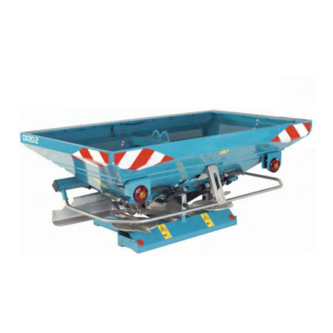
Sulky DX 20 User manual

Sulky

Sulky DX 20 User manual

Sulky Isobus X40 User manual

Sulky

Sulky Isobus X40 User manual

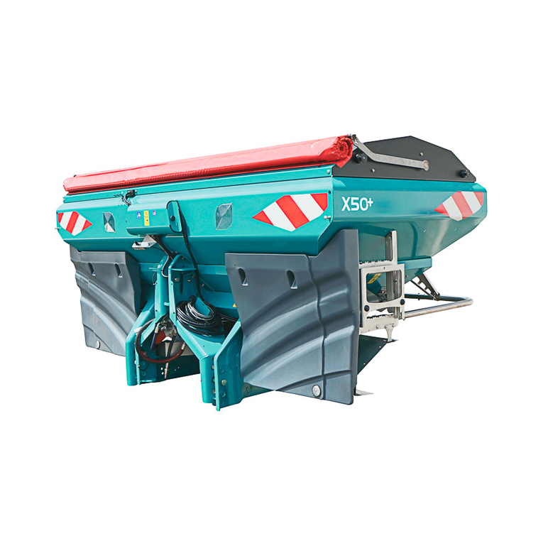
Sulky X50+ 2400 Operation instructions

Sulky

Sulky X50+ 2400 Operation instructions

Popular Spreader manuals by other brands

XtremepowerUS 65057 Owner's manual and safety instructions

XtremepowerUS

XtremepowerUS 65057 Owner's manual and safety instructions

Earth Way 2130 High-Output Assembly and operating instructions

Earth Way

Earth Way 2130 High-Output Assembly and operating instructions

Tube-Line NITRO 275RS Operator's manual

Tube-Line

Tube-Line NITRO 275RS Operator's manual

Earth Way EV-N-SPRED 2150 Assembly instructions

Earth Way

Earth Way EV-N-SPRED 2150 Assembly instructions

Earth Way M80ECM Assembly instructions

Earth Way

Earth Way M80ECM Assembly instructions

OEM Tools 26679 Operating instructions and parts manual

OEM Tools

OEM Tools 26679 Operating instructions and parts manual

Earth Way M30 Operation and assembly manual

Earth Way

Earth Way M30 Operation and assembly manual

Boss Snowplow TGS 800 owner's manual

Boss Snowplow

Boss Snowplow TGS 800 owner's manual

Agri-Fab SpeedEPart 45-0463 owner's manual

Agri-Fab

Agri-Fab SpeedEPart 45-0463 owner's manual

FUXTEC FX-GS36S Original user manual

FUXTEC

FUXTEC FX-GS36S Original user manual

SNOWJOE sunjoe SJ-WBS70 Operator's manual

SNOWJOE

SNOWJOE sunjoe SJ-WBS70 Operator's manual

Roto-Spread 532-16 Operation and parts manual

Roto-Spread

Roto-Spread 532-16 Operation and parts manual

Trynex International SnowEx Precision Pro SP-1675 owner's manual

Trynex International

Trynex International SnowEx Precision Pro SP-1675 owner's manual

Fisher WB-100B Owner's manual and installation instructions

Fisher

Fisher WB-100B Owner's manual and installation instructions

AGI NECO Spread-Rite Series Assembly, operation and parts manual

AGI

AGI NECO Spread-Rite Series Assembly, operation and parts manual

hillvert HT-TEMPLE-1N user manual

hillvert

hillvert HT-TEMPLE-1N user manual

Chapin 8000A Assembly / operation instructions / parts

Chapin

Chapin 8000A Assembly / operation instructions / parts

APV ES 100 M1 Classic Original operating instructions

APV

APV ES 100 M1 Classic Original operating instructions

manuals.online logo
manuals.online logoBrands
  • About & Mission
  • Contact us
  • Privacy Policy
  • Terms and Conditions

Copyright 2025 Manuals.Online. All Rights Reserved.