Sullair SM160 User manual

SM-160 to SM-800
MAINTENANCE MANUAL
DATE : 22Sep2004 REVISION : 1
domnick hunter limited, Dukesway, Team Valley trading Estate, Gateshead, England, NE11 0PZ. Tel: +44 (0) 191 4029000 Fax:+44 (0) 1914826296

Page 2 of 36
FOREWORD
The compressed air dryer systems have been designed and manufactured to ensure that
maximum safety and performance is achieved. It is expected that users of these systems
will employ safe working practices and ensure that when installing, commissioning,
operating or maintaining the equipment, any legal requirements are fulfilled. For example,
in the UK, users should refer to the Health and Safety Act, 1974.
All ancillary equipment such as pipework, valves, fittings etc., must be suitable for the
pressures and capacities involved.
Replacement parts are available from your distributor or the manufacturers ( see front page
for information). The adoption of a regular servicing policy is strongly recommended and
will result in ensuring that a high performance is achieved. Serial numbers and customer
order numbers should be referred to in any communication. (Serial numbers can be found
on the identification plate on the left hand side of the instrumentation shroud). The figure
number and the appropriate diagram in this manual and the item number (shown in circle,)
will also assist in part identification.
Any warranty will be invalidated if the dryer is not commissioned in accordance with the
manufacturers recomendations or non-approved parts substituted. Substitute parts could
reduce the performance or service life in addition to creating potential hazards.
The manufacturers reserve the right to modify the contents of this manual without notice.
The data given is a guideline to users and in no way binding on the manufacturers.
BEFORE SERVICING OR DISMANTLING ALL PRESSURE MUST BE RELEASED FROM
THE SYSTEM AND ITS ASSOCIATED PIPEWORK AND ANY ELECTRICAL SUPPLY
ISOLATED.
Page 3 of 36
RECOMMENDED ROUTINE MAINTENANCE
Daily
1. Open kaddis drains on lower manifold and valve housings to discharge any entrained
condensate.
2. Ensure ’power on’ light is illuminated .
Monthly
As above and include:
1. Ensure all manifold, valve housing and end plate gaskets do not leak.
2. Check all control valves, pipe and fittings (within instrumentation shroud) for air leaks.
Page 4 of 36
MAXI MAINTENANCE
CONTENTS
Section
A1
A2
A3
A4
A5
A6
A7
A8
Description
Inlet Valve Assembly
Manifolds
Exhaust Valve Assembly
Column Assemblies
Outlet Valve Assembly
Control & Instrumentation
Piping & Wiring Diagrams
Fault Finding Guide
Page
5
8
14
16
19
21
26
32

Page 5 of 36
SECTION A1
INLET VALVE ASSEMBLY
A1.1
A1.2
A1.3
Inlet Head Removal
Inlet Valve Disc Removal
Cylinder Piston Seal Renewal

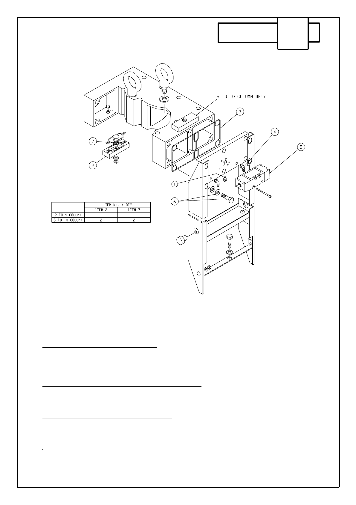
INLET VALVE ASSEMBLY SECTION A1
A1.1 Inlet Head Removal
Remove inlet flange nuts and nylon pipes. Remove Allen screws from cylinders and pull back
cylinders. The bolts from the head assembly can now be removed.Take care when removing the valve
strike plate.
A1.2 Inlet Valve Disc Removal
Secure valve stem and unscrew retaining nut. Inspect strike plate before re-fitting.
A1.3 Cylinder Piston Seal Renewal.
Remove 4 allen screws from cylinder body, secure piston across flats and unscrew valve stem.
Remove circlip from cylinder body and pull out piston. New seals should be fitted using silicon free
grease, press out retaining cover nose seal and renew.
For re-assembly, follow reverse procedure always fitting new moulded gaskets, and ’O’ ring on center
head bolt.. Ensure that the strike plate is located with it’s recessed side towards the valve disks.
TORQUE HEAD BOLTS TO 34Nm (25lbs.ft).
Page 6 of 36
Page 7 of 36
SECTION A2
UPPER & LOWER MANIFOLDS
A2.1
A2.2
A2.3
A2.4
A2.5
A2.6
A2.7
Upper Manifold Removal (Heatless)
Quick Re-Pressurisation Valve Removal (H/L)
Purge Plate Removal
Purge Adjustment
Lower Manifold Removal
Bolt Torque Sequence HEATLESS.
Bolt Torque Sequences - Inlet, Outlet & Exhaust
Valve Assemblies
UPPER & LOWER MANIFOLDS SECTION A2
A2.1 Upper Manifold Removal (Heatless)
Remove nylon pipes from end plate,remove bolts from end plate connected to side plates, disconnect
QRV solenoid coil, remove shroud as detailed in section A6, remove outlet housing as detailed in
section A5. Slacken and remove bolts in the reverse order of torque sequences shown. Screw in M12
location studs. Lift manifold off using eye bolts provided.
A2.2 Quick Re-pressurisation Valve Removal (Heatless)
The QRV can be removed without removing the end plate, by removing the four retaining bolts.
Disconect QRV soleniod coil.To service the valve, remove the end cap and withdraw the piston, clean
piston and refit. (Lubrication is not recomended).
A2.3 Purge Plate Removal (Where Applicable)
Remove outlet housing as shown in Section A5. This will give access to 2 Hex. head screws securing
the purge plate, slacken and remove. The purge plug ‘O‘ ring can be changed by pressing the brass
purge plug clear from the purge plate.
Page 8 of 36

Page 9 of 36
A 2.4 PURGE ADJUSTMENT
A2.4 Purge Adjustment
Before attempting any adjustments to the purge on the
Maxi Smart Dryers ensure that the dryer is in
re-pressurisation.
At this point switch off the electrical supply to the dryer.
Find and locate the solenoid control valves for INLET
VALVE A and EXHAUST VALVE B.
Manually turn the over-ride on Inlet valve A to the
open position.
Manually turn the over-ride on the Exhaust valve B to
the open position. Column B will now de-pressurise.
Unscrew the two exhaust silencers located in the control shroud at the front. Using a 1" BSP plug, blank off one
of the exhaust ports so that all the purge air escapes through one port. Ensure that the flow meter to be used
has a full scale deflection larger than the required purge flow.
Using 1" BSP flexible hose, connect from the exhaust port to the inlet of the flow meter NB. never allow the
float of the flow meter to go off the top of the scale, and never pressurise the flow meter.
Using the brass purge plug, adjust the purge flow to the correct flow rate for the dryer, this must be carried out
with the dryer at its MINIMUM operating pressure. On certain dryers there will be two purge plugs, on these
dryers it is recommended that the plug nearest the inlet and outlet be fully open and the plug nearest the control
shroud be used for fine adjustment.

Page 10 of 36
A 2.4 PURGE ADJUSTMENT
Once the purge flow is set, remove the flow meter and the 1" BSP plug and replace the silencers. Return the
over-ride switches to the correct position. Re-install the electric supply to the dryers and ensure the dryer
cycles correctly.
Purge Settings
Specific purge setting may vary from site to site according to operational/enviromental conditions. In general for
up to 35˚C inlet temperatures the table below gives recommended flow settings for both -40˚C and -70˚C PDP.
Purge flow rates are factory set to 6 barg. This may need to be re-set by a domnick hunter trained installation
engineer at other operatiing pressures during commissioning
MAXI HEATLESS
CODES
SM160
SM240
SM320
SM400
SM480
SM560
SM640
SM800
PURGE FLOW RATE
L/M
714
1070
1427
1784
2141
2498
2855
3568
Page 11 of 36
A 2.5 LOWER MANIFOLD REMOVAL
A2.5 Lower Manifold Removal
Remove inlet and outlet pipes as detailed in section A1 and A5 respectively, remove exhaust silencers as
shown in section A3. Remove shroud as detailed in A6. Remove the two eye bolts on the top manifold and
invert the dryer completely. Remove the nylon pipes from the changeover valve and slacken bolts in the
reverse order of torque sequence shown and lift manifold clear.

Page 12 of 36
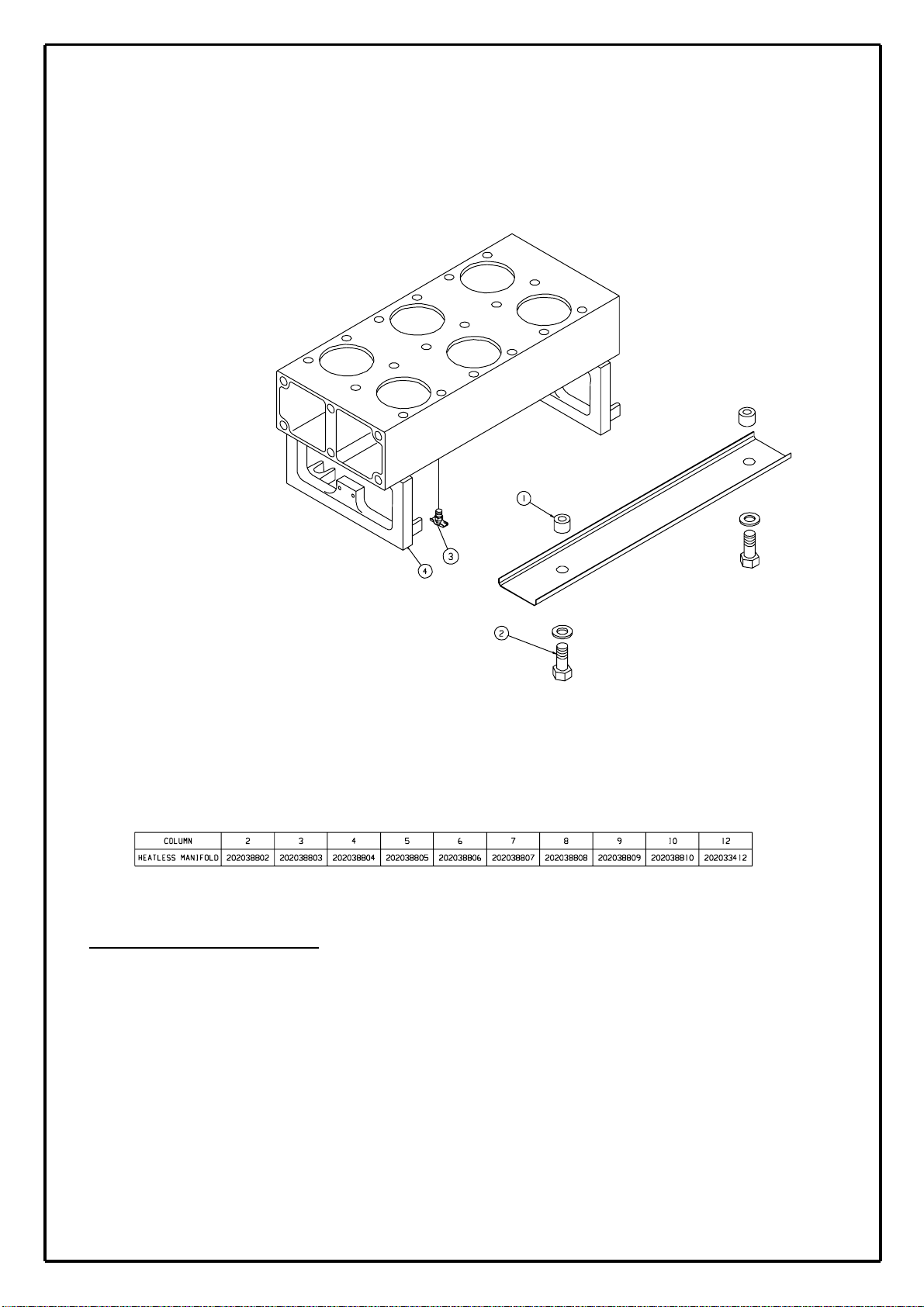
MANIFOLDS - Bolt Torque Sequence
Note:
Tighten the bolts in the numerical order shown, always starting with the middle
column working outwards.
TORQUE to 35N.m (25lbs.ft)
A2.6 -HEATLESS

Page 13 of 36
A 2.7 INLET, OUTLET & EXHAUST VALVE
Bolt Torque Sequence
When removing or assembling the INLET VALVE,
OUTLET VALVE or EXHAUST VALVE housings always
loosen and tighten in the sequence shown above
TORQUE TO 34Nm (25lbs.ft)

Page 14 of 36
SECTION A3
EXHAUST VALVE ASSEMBLY
A3.1
A3.2
A3.3
Exhaust Valve Removal.
Exhaust Valve Disc Removal.
Cylinder Piston Seal Renewal.

EXHAUST VALVE ASSEMBLY SECTION A3
A3.1 Exhaust Valve Assembly Removal.
Unscrew exhaust elements. Remove assembly bolts and nylon pipes. Take care when removing the
valve strike plate.
A3.2 Exhaust Valve Disc Removal.
Secure valve stem and unscrew retaining nut. Inspect strike plate before re-fitting.
A3.3 Cylinder Piston Seal Renewal.
Remove 4 cap screws from cylinder body, secure piston across flats and unscrew valve stem. Remove
circlip from cylinder body and pull out piston. New seals should be fitted using silicon grease, press out
retaining cover nose seal and renew.
A3.4 Exhaust Element Replacement
Unscrew element and replace, ELEMENTS ARE NOT REUSABLE.
For re-assembly, follow reverse procedure always fitting new graphite gaskets and ’O’ rings on
retaining bolts.
Page 15 of 36

Page 16 of 36
SECTION A4
COLUMN ASSEMBLY
A4.1
A4.2
Column/Desiccant Removal
Desiccant Replacement

COLUMN ASSEMBLY SECTION A4
A4.1 Column/Desiccant Removal
Remove upper manifold as described in manifold section remove gasket retaining screws and remove
gaskets. The desiccant can now be extracted from the column using a vacuum cleaner. Bottom column
bolts can then be removed and the column lifted clear
A4.2 Desiccant Replacement
Ensure columns are free from dust and that the lower manifold gasket is in good condition. Refilling can
now take place. In order to maintain dryer performance, the columns must be refilled using a snow storm
filling device which will achieve maximum packing density. The best results are obtained by using a
smooth and continuous operation.
HEATLESS
Page 17 of 36
Page 18 of 36
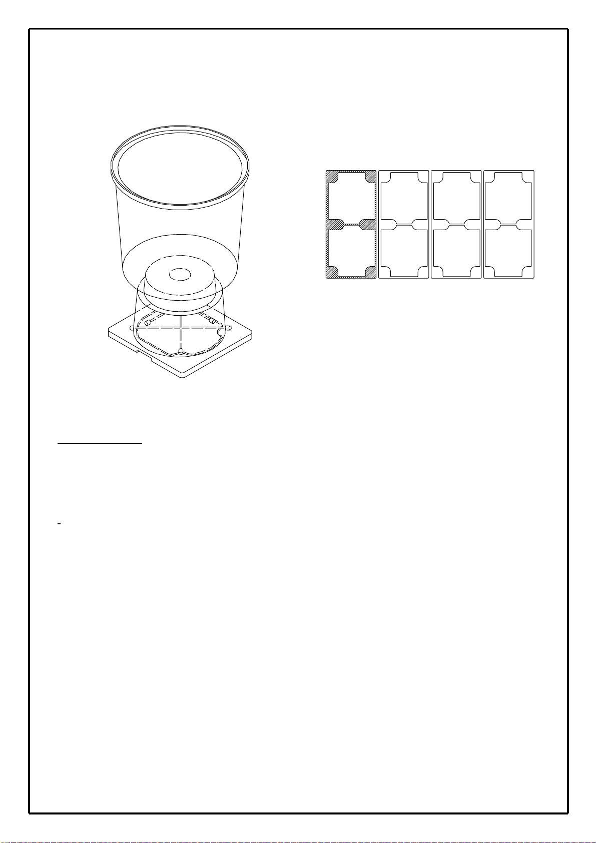
Desiccant Replacement
A4.2.1 GENERAL
Each extrusion consists of 2 E-shaped chambers containing a total of 15kg of desiccant material. Sullair
suggests a performance life of 10,000 - 30,000 hours, however, many factors can influence this nominal
figure which should only be used as a guide. Accurate dewpoint monitoring with a hygrometer is the only true
indication of the desiccant condition ( consultSullair ).
HEATLESS COLUMN ARRANGEMENT

Page 19 of 36
SECTION A5
OUTLET VALVE ASSEMBLY
A5.1
A5.2
Outlet Housing Removal
Outlet Valve Disc Removal

OUTLET VALVE ASSEMBLY SECTION A5
A5.1 Outlet Housing Removal.
Remove outlet flange nuts, head bolts and nylon pipes. Take care when removing the valve strike plate
A5.2 Outlet valve disc removal
Remove valve and spring from guide, secure valve stem and unscrew retaining nut. Inspect strike plate
before re-fitting.
For re-assembly follow reverse procedure. Always fitting new graphite gaskets, seals and o-ring on
centre retaining bolt.
Page 20 of 36
This manual suits for next models
7
Table of contents
Other Sullair Industrial Equipment manuals


