Sullair WSPC User manual

WSPC
USER INTERFACE MANUAL
FOR THE WS CONTROLLER™
Part Number
02250167-859
©Sullair Corporation
KEEP FOR
FUTURE
REFERENCE

Microsoft.net® is a registered trademark of Mircosoft® Corporation.
Windows® is a registered trademark of Mircosoft® Corporation.
AIR CARE SEMINAR
TRAINING
Sullair Air Care Seminars are courses that provide hands-on instruction in the proper operation, maintenance
and service of Sullair equipment. Individual seminars on Industrial compressors and compressor electrical
systems are presented at regular intervals throughout the year at a dedicated training facility at Sullair’s
corporate headquarters in Michigan City, Indiana.
Instruction includes discussion of the function and installation of Sullair service parts, troubleshooting of the
most common problems, and actual equipment operation. The seminars are recommended for maintenance
and service personnel.
For detailed course outlines, schedule and cost information contact:
Sullair Customer Care Training Department
1-888-SULLAIR or 219-879-5451 (ext. 5363)
www.sullair.com
Or Write -
Sullair Corporation
3700 E. Michigan Blvd.
Michigan City, IN 46360
Attn: Service Training Department

WSPC USER INTERFACE
PART 1 USER LEVEL......................................... 1
SECTION 1 OVERVIEW........................................................................................3
1.1 Manual Contents........................................................................................3
1.2 SYSTEM COMPATIBILITY........................................................................4
1.3 Installing the WSPC User Interface Software ............................................4
1.4 Installing OR UPDATING the FRAMEWORK............................................5
1.5 Uninstall the WSPC Software....................................................................5
SECTION 2 GETTING STARTED..........................................................................7
2.1 Access PRIVILEGES.................................................................................7
2.2 Starting the Software .................................................................................7
2.3 Windows® Basic........................................................................................9
2.4 Connecting the PC to the Controller ........................................................10
2.5 Connecting / Disconnecting the WSPC User Interface and the WS
Controller.................................................................................................10
2.6 The WSPC Display Screen......................................................................12
2.7 Compressor Status Bar............................................................................12
2.8 File Menu.................................................................................................14
SECTION 3 WSPC DISPLAY DESCRIPTIONS ..................................................15
3.1 Compressor Status Bar............................................................................15
3.1.1 Status Bar Components ...............................................................15
3.2 Compressor Data Display (Default Screen).............................................16
3.2.1 Compressor Run Data..................................................................16
3.2.2 Digital Inputs and Relay Outputs..................................................17
3.3 Machine Info Display................................................................................18
3.4 Service Display........................................................................................19
OPERATOR IS REQUIRED TO READ
ENTIRE INSTRUCTION MANUAL

WSPC USER INTERFACE
3.4.1 Sensor Details Button...................................................................20
3.4.2 Log Data Button ...........................................................................22
3.5 Maintenance Display ...............................................................................23
3.5.1 Warning Messages.......................................................................23
3.5.2 Service Reminders.......................................................................24
3.6 Distributor Information..............................................................................25
3.7 Sequence System Display.......................................................................25
3.8 Adjustments Display ................................................................................27
3.8.1 Adjusting Control Parameters ......................................................28
3.8.2 Adjustable Control Parameters.....................................................29
3.8.3 Adjusting Sequence Parameters..................................................30
3.8.4 Changing Controller Units and Language Preferences................32
3.8.5 Time and Date Adjustments.........................................................33
3.8.6 Communication Parameters.........................................................34
3.8.7 Internet Transmission Settings.....................................................35
3.8.8 Saving Parameter Settings...........................................................36
3.8.9 Editing and Searching Machine Profiles.......................................36
3.8.10 Loading Parameter Settings.........................................................37
SECTION 4 SETTING USER PREFERENCES...................................................39
4.1 User Profiles............................................................................................39
4.1.1 User Profile Option.......................................................................39
4.1.2 Edit a Profile.................................................................................41
4.1.3 Copy a Current Profile to a New Profile........................................43
4.1.4 Activate a profile...........................................................................44
SECTION 5 VARIABLE SPEED DRIVE (VSD) ...................................................45
5.1 VSD Operation.........................................................................................45
5.2 Compressor Data Tab..............................................................................45
5.3 VSD Performance Data ...........................................................................46
5.4 Clear Recent Data ...................................................................................47
5.5 Delivery History........................................................................................48
5.6 Service Display Tab.................................................................................49
5.7 Main Motor VFD Status Box ....................................................................50
5.8 Adjustments Tab......................................................................................51
5.9 Administrator Level VSD Adjustments.....................................................52

WSPC USER INTERFACE
PART 2 ADVANCED FUNCTIONS.................... 55
SECTION 6 ADMINISTRATOR LEVEL FUNCTIONS.........................................57
6.1 Administrator Level Functions..................................................................57
6.2 Accessing the Administrator Level...........................................................57
6.3 Commissioning a Controller.....................................................................58
6.4 Maintenance Display ...............................................................................60
6.4.1 Warning History Window..............................................................62
6.4.2 Maintenance History Window.......................................................63
6.5 Administrator Adjustments (Admin) Display.............................................64
6.5.1 Signal Address Function ..............................................................65
6.5.2 Digital Input Options (drop-down arrows).....................................65
6.5.3 Factory-Defined Output Options (drop-down arrows)...................66
6.5.4 Analog Signal Zero Trims.............................................................66
6.5.5 Maximum User Unload Settings...................................................66
6.5.6 Disable Warning Reset.................................................................67
6.5.7 Assigning Digital Inputs................................................................67
6.5.8 Unload (Remote) Button...............................................................68
6.5.9 Sensor Calibration........................................................................68
6.5.10 P2 Pressure Transducer Calibration ............................................68
6.5.11 VSD Package Settings.................................................................69
6.5.12 Saving and Loading Administrator Parameters............................71
6.5.13 Import Commission Data..............................................................71
6.5.14 Import Other Data.........................................................................72
6.6 Modbus Functions ...................................................................................73
6.6.1 Monitoring Modbus communications............................................74
6.6.2 Reading and writing specific registers..........................................74

WSPC USER INTERFACE

WSPC USER INTERFACE
1
PART 1
USER LEVEL

WSPC USER INTERFACE

Part 1: User Level WSPC USER INTERFACE
3
SECTION 1 OVERVIEW
The WSPC User Interface is a Windows-based software program that allows
complete monitoring and control of Sullair air compressors equipped with a
Sullair WS Controller. The software can monitor a single compressor operating
as an individual unit or multiple machines connected in a sequence. The WSPC
program receives data about the compressor from the WS Controller, assigns
control parameters to the controller, displays controller operating characteristics
including faults and warning messages, and provides functionality that assists the
user with controller diagnostics.
1.1 MANUAL CONTENTS
This manual describes the features and operation of the WSPC User Interface
program. Part 1 covers material pertaining specifically to persons operating the
program with User Level access. Part 2 covers advanced functions available to
experienced users and persons with Administrator Level access.
This manual describes WSPC software part number 02250165-416, when
operated with WS Controller software 02250165-315 or later. This version of
WSPC is compatible with all previously released versions of WS Controller
software, but certain features described in this manual are not available in earlier
versions.
Part 1:
Section 1 provides the necessary information to install the WSPC software.
Included are the minimum hardware and software requirements.
Section 2 presents steps to getting the program up and running quickly. Basic
MS Windows functions and those features necessary to using the software are
explained in this section.
Section 3 provides an explanation of each display screen available to user level
operators. Detailed descriptions of the operation of each display component are
provided.
Section 4 provides steps to setting user preferences for operating the WSPC
program. This section guides the user in creating and modifying user profiles.
Section 5 describes the WSPC functions that apply to Variable Speed Drive
compressors.
Part 2:
Section 6 describes those functions that apply specifically to Administrator level
operators. Each administrator level display is presented and details of the
display components are described.

WSPC USER INTERFACE Part 1: User Level
4
Features of the WSPC User Interface software include:
•Two-way communication channel between the user and the compressor
controller.
•A comprehensive view of the compressor controller’s operation at the WSPC
interface.
•Adjustment of all modifiable parameters of the compressor controller.
•Ability to control the compressor remotely.
•Access to data relating to all compressors connected as a sequence system.
•Password protection capabilities to limit access to data and controls.
•A data log feature which compiles operational, service, and error data of the
compressor or compressor system.
1.2 SYSTEM COMPATIBILITY
Before beginning the installation process, your computer should meet the
following minimum requirements.
•PC–compatible computer (Pentium® IV based, 1.0 Ghz processor
recommended)
•Windows 2000 or Windows XP operating systems. Windows 2000 may
require special processing software to properly operate the WSPC software.
•CD ROM drive
•125 Mb of available hard disk space
•256 Mb of available RAM memory
•Color monitor
•RS232 communications capability
1.3 INSTALLING THE WSPC USER INTERFACE SOFTWARE
Follow the instructions accompanying the WSPC Installation package. The
actual installation media may be CD, internet, network, memory sick, or other
means, and the procedure will be specific to that media. This installation will
create a folder on your disk drive, and install the necessary files into that folder.
Make a note of this location, as it may be necessary for future updates. The
default location for all saved files will also be in that folder, but you may browse
to save into any other location in your PC as desired. By default, the folder will
be “WSPC, and will be located in a “Sullair” folder: “..\Sullair\WSPC”

Part 1: User Level WSPC USER INTERFACE
5
1.4 INSTALLING OR UPDATING THE FRAMEWORK
The WSPC software requires the Microsoft .net® Framework support program in
order to run on the PC. If Microsoft .net is already on the PC, you will be able to
run as soon as the installation is completed. To install the framework, or update
to the latest version, use the following procedure for a free download.
1. Connect the PC to the internet.
2. Go to the site: www.microsoft.com/downloads
3. Search for “.NET Framework”
4. Follow the instructions for downloading and installation.
1.5 UNINSTALL THE WSPC SOFTWARE
To uninstall the WSPC software:
1. Right-click any desktop shortcuts that were created.
2. Click “Delete” to delete the shortcut.
3. Open “My Computer” and browse to the folder created in Section 1.3.
4. Delete the folder and its contents.
NOTE
Contact your network administrator if you are unable to perform the software
installation due to access limitations.

WSPC USER INTERFACE Part 1: User Level
6
NOTES
Part 1: User Level WSPC USER INTERFACE
7
SECTION 2 GETTING STARTED
2.1 ACCESS PRIVILEGES
The WSPC User Interface program may be accessed at two levels.
User Level: Allows users to access the program without entering a password.
The user should be an individual with specific authorization to use the WSPC
software and knowledge of the compressor operation. This level includes all
data and adjustments for normal applications of the compressor. At this level a
user has access to the following displays: Compressor Data, Machine Info,
Service, Maintenance, Sequencing, and Adjustments.
Administrator Level: This provides additional functions for maintenance,
service, and setup for trained compressor technicians. Administrator level
functions are described in Part 2 of this manual. A password is required to
access this level.
2.2 STARTING THE SOFTWARE
1. Click the shortcut located on the computer desktop to start the WSPC
User Interface program.
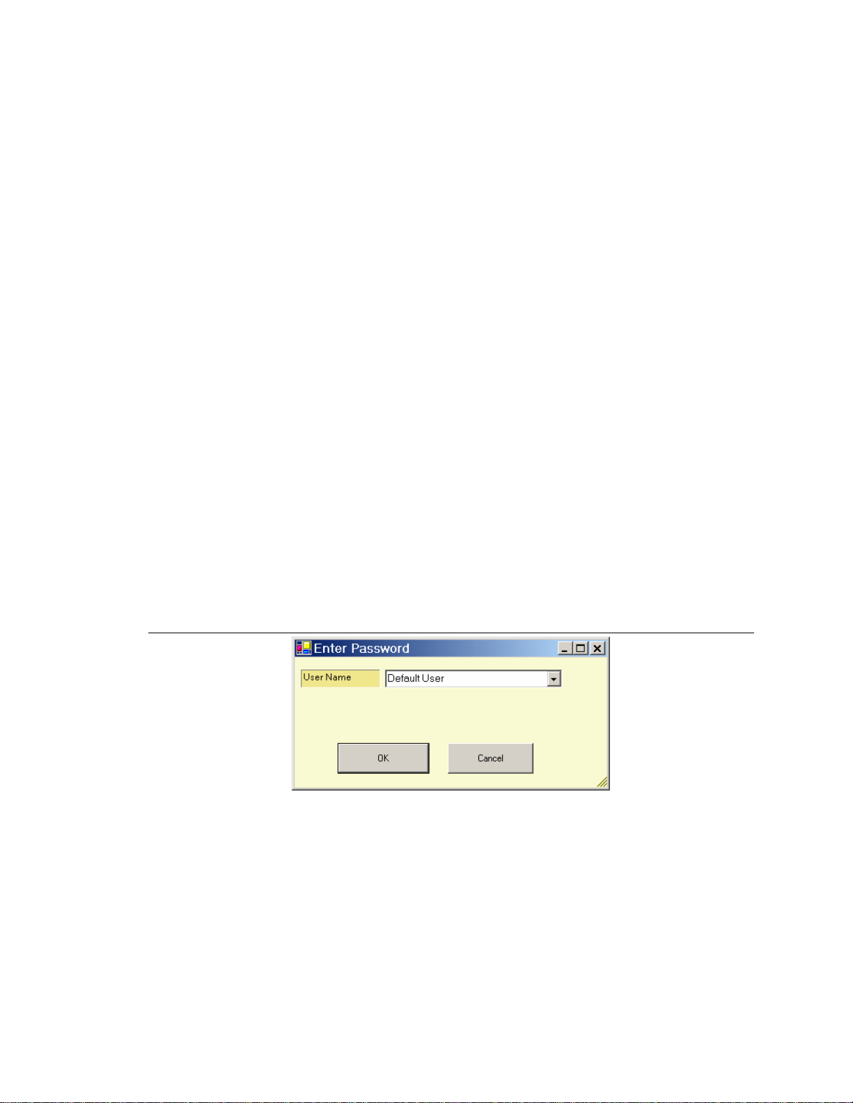
2. When the program opens, a dialog box will appear as shown in Figure
2.1a. Click OK to open the WSPC program.
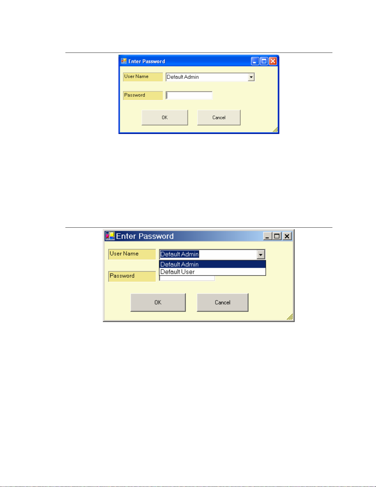
If the program was last closed while operating at the Administrator level
the dialog box will require a password as shown in Figure 2.1b.
Figure 2.1a WSPC User Interface password request
WSPC USER INTERFACE Part 1: User Level
8
Figure 2.1b WSPC User Interface password request
Do the following to select a user-level profile:
a. Click the down arrow next to the “User Name” box. A drop-down
list of user profiles will be presented. See Figure 2.2.
b. Click on a profile that is set for “User Level” access (Default User)
and click “OK”. User level profiles do not require password access.
More profile options may be available in the User Name list than
the ones shown in Figure 2.2.
Figure 2.2 User Option
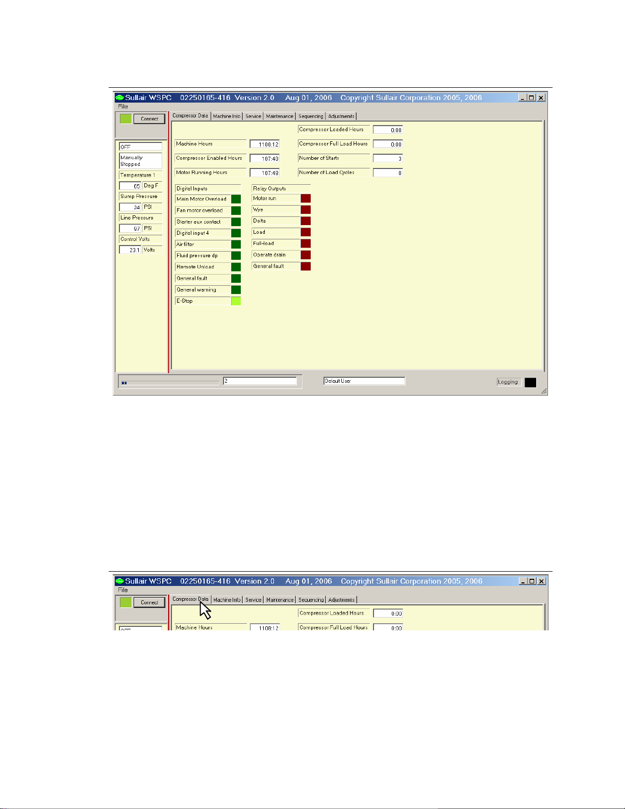
3. The program will open to the “Compressor Data Display” with user level
access. See Figure 2.3. From the opening screen the user may navigate
to all other features of the program.
Part 1: User Level WSPC USER INTERFACE
9
Figure 2.3 WSPC Opening Window – Compressor Data Display
2.3 WINDOWS® BASIC
This section presents basic MS Windows® functions that will be useful to using
the WSPC program. The active presentations of information on the computer
screen are referred to as “Displays.” At the top of each display is a tab showing
the display title.
To make a display active, click on the desired display tab. See Figure 2.4. The
active display allows the user to see the data related to the tab title and to
perform functions on the display page.
Figure 2.4 User Interface display tab
Some screens allow for entry of values into fields on the screen.
To enter data into a field:
a. Click in the field to be modified.

WSPC USER INTERFACE Part 1: User Level
10
b. Select the data currently contained in the field (if any). Data in a field can
be selected by double-clicking on a character in a field. The entire data
field will be selected. Data can also be highlighted for editing by holding
down the left mouse button and dragging the cursor across the data in the
field.
c. Type the new data into the field. Typing the new data will replace the old
data.
Typically an option can be chosen by pressing “Enter” on the computer keyboard.
Some options present a dialog box that allow the user to confirm the entries by
clicking an “OK” button or cancel the entries by clicking “Cancel.”
A window can be reduced, expanded, or closed by clicking on the respective
button located in the upper right corner of the display:
Reduce Expand Close
.
2.4 CONNECTING THE PC TO THE CONTROLLER
The standard connection of the PC Interface to the WS Controller is via a
specially designed RS-232 connector. This serial line connects to the computer’s
DB9 socket and runs directly to a custom designed terminal located on the left
side of the controller cabinet. The PC may also be connected to the controller
by other means such as through RS-485 connections or remotely via modem or
wireless network.
2.5 CONNECTING / DISCONNECTING THE WSPC USER INTERFACE
AND THE WS CONTROLLER
After the communication lines are attached and the WSPC software is running,
the WSPC program can be connected to the controller to begin receiving
machine operation data. Control data can also be sent from the PC to the WS
Controller to configure the machine control parameters.
1. To establish connection between the WSPC and the WS Controller click
(“Connect” button) in the status bar.
The box left of the Connect button will appear bright green indicating the
connection is active. The software will search for communication from the
controller, and fill the display with machine information.
2. During normal connection, communication activity will be shown on the
bottom edge of the WSPC screen, as shown in Fig 2.5a. The progress
bar and block numbers simply indicate that communications are occurring.
The WS Controller also provides led indicators for communication near
J13. Red indicates a request was received from the PC, Green indicates
a message is being sent to the PC.

Part 1: User Level WSPC USER INTERFACE
11
Figure 2.5a WSPC User Interface Display Screen
3. If communication with the machine could not be established, an error
message will display on the communication status line as depicted in
Figure 2.5b. If this occurs, check the RS-232 connection and other
terminals for proper connection.
Figure 2.5b WSPC User Interface Display Screen
4. To disconnect communication between the WSPC and the controller, click
on the “Connect” button. The box left of the button will change from bright
green to dark, shaded green, indicating that the WSPC is disconnected
from the controller. The controller will continue to operate according to the
latest set of parameters entered.
Figure 2.6 WSPC User Interface Display Screen
Logging
Indicator
Compressor
Status Ba
r
Machine
Operation Data
and Parameters
Display TabsTitle Bar
File Menu
Connection
Button
Communication
Status Indicator User Profile
Name

WSPC USER INTERFACE Part 1: User Level
12
2.6 THE WSPC DISPLAY SCREEN
The WSPC display screen consists of the title bar, the pull-down menu bar, the
compressor status bar, display tabs, machine operation data display, and the
communication status bar. Refer to Figure 2.6. The default screen is the
Compressor Data display which appears each time the WSPC software is
opened. Listed below are main elements of the screen display that enable the
user to access and view the machine operation data, and modify the machine
control parameters.
Title Bar – Contains the name, part number and version of the WSPC
software program.
File Menu – Drop-down Menu that allows the user to select configuration
options. Available options are Profiles (to create and edit profiles), Login (to
select User login profile), and Exit. The “Commission” selection is available
only with Administrator level access.
Connection Button – When activated, establishes connection between the
PC Interface and the WS Controller unit.
Compressor Status Bar – Located on the left margin of every display, the
Compressor Status Bar provides real-time data of the machine’s current
operation and condition. The Compressor Status Bar is described in detail in
Section 2.7.
Display Tabs – Allow for the selection of the desired display. Section 3
provides a detailed description of each display screen.
Machine Operation Data – Area where the machine parameter data and
operational information is displayed.
Communication Status Indicator – Located at the bottom of the display
window, this line provides communication status information.
User Profile Name – The name of the current user profile is displayed. In
Figure 2.6, the active profile is named “Default User”.
Logging Indicator – This field will light when the PC is recording data.
2.7 COMPRESSOR STATUS BAR
The Compressor Status Bar, which is located left of the main window, displays
real-time data regarding the status of the compressor. The status bar is
constantly displayed whenever the WSPC software is connected to the controller.
This feature allows the user to quickly view the status of the compressor
operation regardless of which display screen is active. Information presented in
the status bar includes the compressor operating mode, operating state,
compressor temperature, sump pressure, and discharge pressure. See Figure
2.6.
The Compressor Status Bar can be displayed as a stand alone compressor
operation monitor as shown in Figure 2.7. The full display window can be hidden

Part 1: User Level WSPC USER INTERFACE
13
leaving only the status bar information appearing on the screen. This feature
allows the user to continue monitoring the compressor operation while
performing other tasks on the PC.
To reduce the display to show only the status bar:
1. Place the cursor on the right border of the WSPC display window.
2. Press and hold the left mouse button.
3. “Drag” the display border to the left until it stops. The compressor data
window will be hidden leaving the status bar in the display.
4. To return to the full screen presentation, click on the expand window
icon in the upper right corner of the display.
5. To return again to the status bar only view, click on the reduce window
icon in the upper right corner of the display.
Figure 2.7 Compressor Status Bar (Reduced)
Compressor
Operating
Mode
Compressor
Temperature
Measurement
Sump
Pressure
Measurement
Compressor
Pressure
Dischar
g
e
Compressor
Operating
State

WSPC USER INTERFACE Part 1: User Level
14
2.8 FILE MENU
The File Menu contains options that allow the user to configure and set
preferences that control how the program functions. See Figure 2.7
From the “File” menu, the user can choose three options:
Profiles – Allows the user to create and edit profiles. A profile will contain
settings that configure the WSPC program according to the operator or group’s
preferences. The features of the Profiles menu option are described in Section 4
of this manual.
Login – Presents the Login box which allows the user to choose a profile from a
list of available User profiles. See Figure 2.9 (a & b).
Exit – Closes the WSPC User Interface program. Exiting the software does not
affect the compressor or controller operation.
Figure 2.8 File Menu Options
Figure 2.9 Login Screen
a. b.
File
Menu
Other manuals for WSPC
1
Table of contents
Popular Recording Equipment manuals by other brands


urmet domus
urmet domus 1067/007 Installation and setup manual

DriverGenius
DriverGenius AV202-B Operating instruction

VADDIO
VADDIO EasyTalk 2.0 999-7230-000 Installation and user guide

ALLEN & HEATH
ALLEN & HEATH WZ312M Service manual

v.LOGiC
v.LOGiC V5-NBT-PNP manual

Harman Kardon
Harman Kardon CDR 20 owner's manual