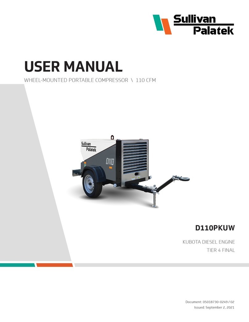
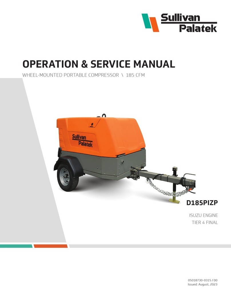
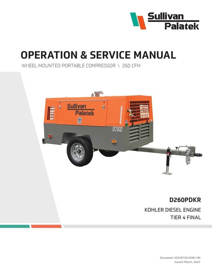
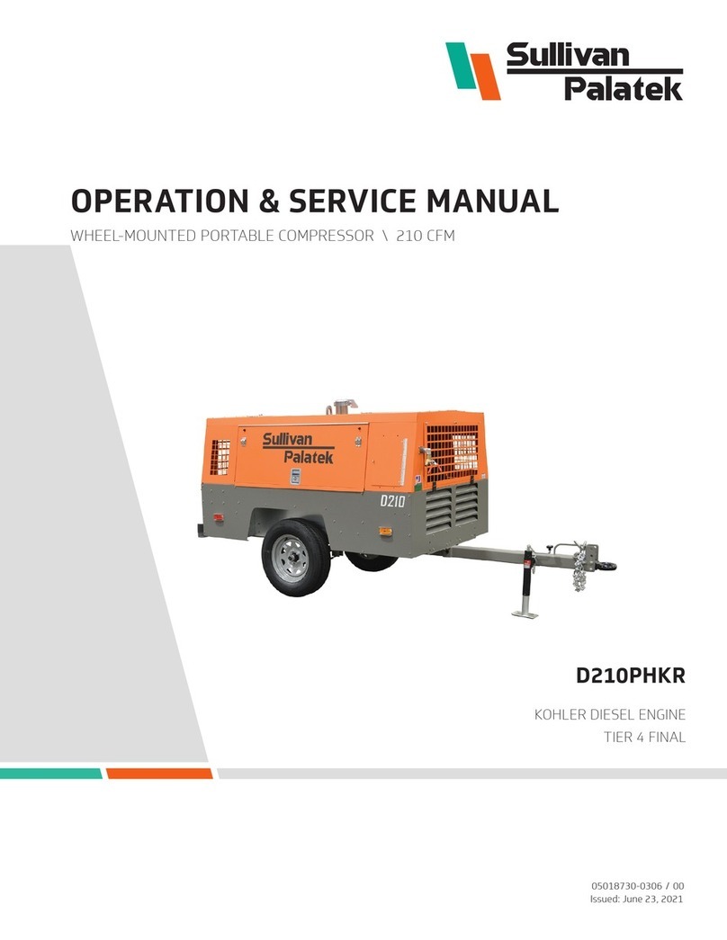
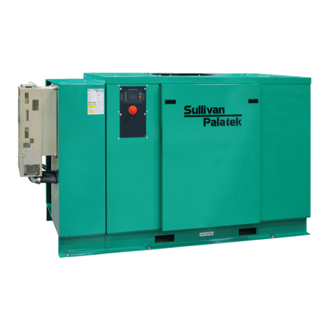
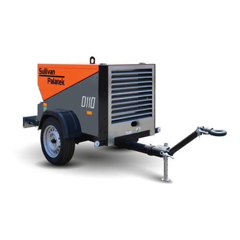
Sullivan-Palatek D185PKR Installation and operating instructions

D185PKR
D185PKRSB
KOHLER DIESEL ENGINE
TIER 4 FINAL
OPERATION & SERVICE MANUAL
WHEEL-MOUNTED PORTABLE COMPRESSOR \ 185 CFM
05018730-0287 / 00
Issued: October 13, 2020

DOCUMENT INFORMATION
© Sullivan-Palatek, Inc.
ALL RIGHTS RESERVED
Part Number: 05018730-0287
Revision: 00
CONTACT INFORMATION
Sullivan-Palatek, Inc.
1201 West US Highway 20
Michigan City, Indiana 46360
Phone: (219) 874-2497
Fax: (219) 872-5043
Toll Free: (800) 438-6203
Website: www.sullivan-palatek.com
RECORD KEEPING
Record the model and serial number of the compressor for
future reference when contacting the factory for service
or parts.
Model Number:
Serial Number:
DISCLAIMER
Although this manual is checked for conformity with the machines
described, we cannot guarantee that all errors will be excluded.
Necessary corrections will be made in future editions of this manual.
This manual is subject to change without notice.
REVISION HISTORY
#DATE SECTION(S) DESCRIPTION
00 2020-10-13 Released for publication

III
I WARRANTY � � � � � � � � � � � � � � � � � � � � � � � � � � � � � � � � � � � � � � � � � � � � � � � � � � � � � � � � � � � � � � V
II ABOUT THIS MANUAL � � � � � � � � � � � � � � � � � � � � � � � � � � � � � � � � � � � � � � � � � � � � � � � � � � � � VII
II.1 Safety Instructions ................................................................vii
II.2 Manual Organization ...............................................................vii
II.3 Supplemental Documents...........................................................vii
1 SAFETY � � � � � � � � � � � � � � � � � � � � � � � � � � � � � � � � � � � � � � � � � � � � � � � � � � � � � � � � � � � � � � � � � � 1
1.1 General Safety .....................................................................2
1.2 Pressure Release ...................................................................2
1.3 Fires and Explosion .................................................................2
1.4 Moving Parts .......................................................................3
1.5 Toxic and Irritating Substances .......................................................4
1.6 Hot Surfaces, Sharp Edges, Sharp Corners and Vacuum ..................................4
1.7 Electrical Shock.....................................................................4
1.8 Entrapment ........................................................................4
2 TRANSPORTING AND LOCATING � � � � � � � � � � � � � � � � � � � � � � � � � � � � � � � � � � � � � � � � � � � � 5
2.1 Receiving ..........................................................................6
2.2 Liing .............................................................................6
2.3 Drawbars and Brake Actuators .......................................................6
2.4 Preparing to Tow ...................................................................7
2.5 Towing ............................................................................7
2.6 Parking or Locating Compressor ......................................................8
3 OPERATION � � � � � � � � � � � � � � � � � � � � � � � � � � � � � � � � � � � � � � � � � � � � � � � � � � � � � � � � � � � � � � 9
3.1 General Operating Safety ...........................................................10
3.2 Preparing for Initial Start-Up ........................................................10
3.3 Normal Starting ...................................................................10
3.4 Normal Stopping...................................................................11
3.5 Sullivan-Palatek Electronic Controller (SPEC) Operational Instructions ....................11
3.6 Operating Under Extreme Conditions .................................................13
3.7 Pneumatic Tools Application.........................................................13
3.8 Jump-Starting Battery .............................................................14
4 COMPONENT DESCRIPTION � � � � � � � � � � � � � � � � � � � � � � � � � � � � � � � � � � � � � � � � � � � � � � � 17
4.1 Portable Compressor Package .......................................................18
4.2 Engine............................................................................18
4.3 Air End Assembly ..................................................................18
4.4 Discharge System..................................................................18
4.5 Lubrication System ................................................................19
4.6 Capacity Control System ............................................................20
4.7 Noise Control Systems..............................................................20
4.8 Electrical and Protective Circuit System...............................................21
4.9 Engine Shutdown Protection ........................................................21
4.10 Instrument Panel ..................................................................22
CONTENTS

IV CONTENTS
5 MAINTENANCE � � � � � � � � � � � � � � � � � � � � � � � � � � � � � � � � � � � � � � � � � � � � � � � � � � � � � � � � � � 25
5.1 Maintenance Schedule..............................................................26
5.2 Bolt Torque Guidelines..............................................................27
5.3 Compressor Lubrication ............................................................27
5.4 WEATHER-ALL™Compressor Lubricant................................................28
5.5 Oil Sample for Analysis .............................................................29
5.6 Air Intake Filter ....................................................................30
5.7 Compressor Oil Filter ...............................................................30
5.8 CompressorShaOilSeal ...........................................................30
5.9 Oil Return Line.....................................................................30
5.10 Air/Oil Separator ...................................................................31
5.11 Thermal Valve .....................................................................31
5.12 Oil Cooler .........................................................................31
5.13 Grease ...........................................................................31
5.14 Engine Lubrication .................................................................31
5.15 Control Adjustments ...............................................................32
5.16 Recommended Spare Parts .........................................................33
5.17 Service Kits .......................................................................33
6 TROUBLESHOOTING� � � � � � � � � � � � � � � � � � � � � � � � � � � � � � � � � � � � � � � � � � � � � � � � � � � � � � 35
6.1 Introduction ......................................................................36
6.2 Unplanned Shutdown ..............................................................36
6.3 Discharge Pressure Is Too Low.......................................................36
6.4 Discharge Pressure is Too High or Relief Valve Blows ...................................37
6.5 Relief Valve Blows with Throttle Lever in Idle Position ..................................37
6.6 PressureDoesNotBlowDownAerShutdown ........................................37
6.7 Compressor Oil Level is Decreasing Excessively ........................................37
6.8 Oil in Service Line ..................................................................37
6.9 Engine Does Not Accelerate Or Will Not Maintain Full Load Speed.........................38
6.10 Separator Plugging ................................................................38
6.11 Engine Speed Control Does Not Change to Idle Speed with Service Valves Closed...........38
6.12 Engine Speed Control Does Not Change to Full Speed with Air Demand....................38
6.13 CompressorOilLeakinginControlLines/Orices .......................................39

VWARRANTY
Sullivan-Palatek Portable Air Compressor
STANDARD WARRANTY
Sullivan-Palatek warrants its new portable air compressor products to be free from defects in material and workmanship,
subject to the following provisions:
Warranty Registration: To validate the warranty for each product the purchaser shall complete and return the Warranty
RegistrationFormwithin30daysofdeliverytotherstuserorrental.
Warranty Period: The warranty period for applicable Sullivan-Palatek products is as follows (subject to the Exclusions and
Limitations noted below):
Air ends on new machines – stator and rotor assembly: Single stagecompressormodels:thersttoexpire;42months
from shipment by Sullivan-Palatek or 36 months from delivery to the rst user. Two stage high pressure compressor
models:thersttoexpire;30monthsfromshipmentbySullivan-Palatekor24monthsfromdeliverytotherstuser.
Remainder of new portable air compressor machines:thersttoexpire;18monthsfromshipmentbySullivan-Palatekor
12monthsfromdeliverytotherstuser.
Parts, accessories and attachments sold separately from machines, excluding warranty replacement parts and hand
tools:thersttoexpire;6monthsfromshipmentbySullivan-Palatekor3monthsfromdeliverytotherstuser.
Warranty replacement parts: remainder of the original warranty period of the replaced part.
Sullivan-Palatek’s Obligations: Sullivan-Palatek’s exclusive obligations under its warranty are (i) to repair or replace any
defective part at Sullivan-Palatek’s option and subject to return of defective parts, (ii) to pay the reasonable cost of making
the repair or reinstalling the replacement part, and (iii) for air compressors having two or more axles, reimbursement of up
to four hours travel labor and up to 200 miles (100 miles travel radius) per event to make repairs. Reimbursement rates for
travel and mileage are set at the discretion of Sullivan-Palatek and are subject to change without notice.
Purchaser’s Responsibility: Purchaser shall (i) give Sullivan-Palatek written notice of any warrantable failure of any
Sullivan-Palatek product within the applicable warranty period, (ii) make the product available for repair at a Sullivan-
Palatek authorized repair facility, (iii) pay all costs of returning failed parts to Sullivan-Palatek, (iv) pay shipping costs for
replacementparts,(v)payreasonabletravelexpensesforeldrepairsperformedatpurchaser’srequest,and(vi)paythe
costs of investigating performance complaints that are not covered by this warranty.
Exclusions and Limitations: Air end seals are not warranted. Engines, tires and batteries are not warranted by Sullivan-
Palatek but are warranted only by the manufacturers of these components. Sullivan-Palatek has no obligation for product
failures or defects resulting from overloading, misuse, neglect, accident, failure to comply with Sullivan-Palatek’s product
manual, or failure to install product improvements provided by Sullivan-Palatek. Use of attachments, accessories or service
parts not supplied or recommended by Sullivan-Palatek may void the warranty of that product. Sullivan-Palatek has no
obligation to pay costs of returning defective parts to Sullivan-Palatek or shipping replacement parts to purchaser.
THIS WARRANTY IS SULLIVAN-PALATEK’S ONLY WARRANTY OF ITS PORTABLE AIR COMPRESSOR PRODUCTS AND IS
IN LIEU OF ANY OTHER WARRANTIES, EXPRESS OR IMPLIED. ANY IMPLIED WARRANTIES OF MERCHANTABILITY OR
OF FITNESS FOR A PARTICULAR PURPOSE ARE EXCLUDED. SULLIVAN-PALATEK HAS NO OBLIGATION UNDER THIS
WARRANTY OR OTHERWISE (REGARDLESS OF THE FORM OF ACTION) FOR SPECIAL, CONSEQUENTIAL OR INCIDENTAL
DAMAGES, INCLUDING WITHOUT LIMITATION LOST PROFITS OR LOST INCOME. THE TOTAL RESPONSIBILITY OF
SULLIVAN-PALATEK FOR CLAIMS, LOSSES, LIABILITIES OR DAMAGES, WHETHER IN CONTRACT OR TORT ARISING OUT
OF OR RELATED TO ITS PRODUCTS SHALL NOT EXCEED THE PURCHASE PRICE OF THE COVERED PRODUCT.
ThiswarrantyappliestoallSullivan-PalatekportableaircompressorsshippedaerNovember1,2015unlessexpressly
supersededbyalaterwarranty.Intheeventofanyconictbetweenthiswarrantyandearlierwarrantystatements,the
terms of this warranty will apply.
10.31.15
I WARRANTY

VI WARRANTY

VII
II ABOUT THIS MANUAL
II.1 SAFETY INSTRUCTIONS
Instructions for the safe operation and maintenance of the Sullivan-Palatek air compressor are located
throughoutthismanual.Theseinstructionsarepresentedwithdierentlabelsaccordingtothelevelofrisk
involved, described as follows:
WARNING! is used when death or personal injury could occur if the instruction is not followed.
CAUTION! is used when damage to property could occur if the instruction is not followed.
NOTE! is used to inform the reader of installation, operation or maintenance information that is important but not
hazardous.
II.2 MANUAL ORGANIZATION
Anyone operating or servicing the Sullivan-Palatek air compressor should read this entire manual and be
familiar with its information. The following is a quick guide to the contents in this manual:
SECTION 1: SAFETY
This section contains important basic information regarding general safety precautions for maintaining
and operating air compressors.
SECTION 2: TRANSPORTING AND LOCATING
This section contains instructions and safety guidelines for transporting and locating a portable air
compressor.
SECTION 3: OPERATION
This section contains an overview of general operating safety, initial start-up procedures, how to start and
stop the air compressor, in addition to guidelines for operating under extreme conditions.
SECTION 4: COMPONENT DESCRIPTION
Thissectioncontainsinformationabouthowthedierentsystemsandcomponentsfunctionwithinanair
compressor.
SECTION 5: MAINTENANCE
This section contains a maintenance schedule and step-by-step instructions for performing common
maintenance procedures. A list of recommended spare parts to keep on hand is also included.
SECTION 6: TROUBLESHOOTING
This section contains symptoms, causes and remedies for common air compressor malfunctions.
II.3 SUPPLEMENTAL DOCUMENTS
Formoredetailedinformationoncertaincomponentsoroptionalequipmentspecictothiscompressor,
supplementaldocumentsareprovided,includingtheParts&SpecicationsManual.The Engine manual can
be accessed at www.kohlerpower.com.

VIII ABOUT THIS MANUAL

1
1 SAFETY
TOPICS IN THIS SECTION:
» General Safety . . . . . . . . . . . . . . . . . . . . . . . . . . . . . . . . . . . . . . . . . . . . . . . . . . . . . . . . . . . . . . . . . . . . . . . . . . . . . . 2
» Pressure Release . . . . . . . . . . . . . . . . . . . . . . . . . . . . . . . . . . . . . . . . . . . . . . . . . . . . . . . . . . . . . . . . . . . . . . . . . . . . 2
» Fires and Explosion . . . . . . . . . . . . . . . . . . . . . . . . . . . . . . . . . . . . . . . . . . . . . . . . . . . . . . . . . . . . . . . . . . . . . . . . . . 2
» Moving Parts . . . . . . . . . . . . . . . . . . . . . . . . . . . . . . . . . . . . . . . . . . . . . . . . . . . . . . . . . . . . . . . . . . . . . . . . . . . . . . . . 3
» Toxic and Irritating Substances . . . . . . . . . . . . . . . . . . . . . . . . . . . . . . . . . . . . . . . . . . . . . . . . . . . . . . . . . . . . . . . . 4
» Hot Surfaces, Sharp Edges, Sharp Corners and Vacuum . . . . . . . . . . . . . . . . . . . . . . . . . . . . . . . . . . . . . . . . . . .4
» Electrical Shock. . . . . . . . . . . . . . . . . . . . . . . . . . . . . . . . . . . . . . . . . . . . . . . . . . . . . . . . . . . . . . . . . . . . . . . . . . . . . . 4
» Entrapment . . . . . . . . . . . . . . . . . . . . . . . . . . . . . . . . . . . . . . . . . . . . . . . . . . . . . . . . . . . . . . . . . . . . . . . . . . . . . . . . . 4
CALIFORNIA
PROPOSITION 65 WARNING
Diesel engine exhaust and some of its
constituents are known to the State
of California to cause cancer, birth
defects and other reproductive harm.

2SAFETY
1.1 GENERAL SAFETY
Safety is a prime consideration in the design and manufacture of the compressor components. Ultimately,
the responsibility for safe operation rests with the individuals who use and maintain the compressor.
Thefollowingsafetyprecautionsareoeredasaguideforthesafeoperationandmaintenanceofthis
machinery:
» Only trained and authorized personnel who have read and understand this user’s manual should operate
the air compressor. Failure to follow the instructions, procedures, and safety precautions in the manual
will increase the possibility of accidents and injuries.
» Never start the air compressor unless it is safe to do so. Do not attempt to operate the air compressor
with a known unsafe condition. If an unsafe condition exists or maintenance is required, tag the air
compressor and render it inoperative by disconnecting the battery so others who may not know of the
unsafe condition cannot attempt to operate it until the unsafe condition is corrected.
» Use and operate the air compressor only in full compliance with all pertinent Federal, State and Local
codes or requirements including OSHA, EPA and other relevant agency requirements.
» Do not modify the compressor or install attachments without consulting the manufacturer.
» Known and potential hazards associated with the operating and servicing of portable air compressors
are detailed in the following pages. Not all hazards can be anticipated and the operator of the equipment
is ultimately responsible for identifying hazardous and dangerous conditions, avoiding dangerous
operation and preventing accidents.
1.2 PRESSURE RELEASE
» Removethepressurefromair,oil,andcoolingcircuitsbeforedisconnectingpipes,ttingsorrelated
items. Pay attention to the possible residual pressure when you disconnect a device from a pressurized
circuit.
» Do NOT try to detect pressure leaks with your hands. It is not always possible to identify a leak from
a tiny hole. Use a piece of paper or wood to locate a suspected leakage. Wear safety glasses when
detecting leaks.
» Oil, fuel, or compressed air can cause injuries. Fluid leaking under pressure has enough force to
penetrate under the skin and cause serious bodily injuries.
» Donotopensump(receiver)oilllercapwhencompressorisrunningandairsystemispressurized.Shut
downthecompressorandbleedthesump(receiver)pressuretozerobeforeremovingtheoilllercap.
» Donotremovecoolercapwhiletheengineisrunning,orimmediatelyaertheenginestops.Waituntil
the coolant temperature is below its boiling point, then loosen cap slowly to its stop to relieve any
excess pressure. Make sure coolant is not boiling before removing cap completely, and protect yourself
by wearing safety glasses.
1.3 FIRES AND EXPLOSION
1.3.1 FUEL & LIQUIDS
WARNING!
» Refuel at a service station or from a fuel tank designed for the purpose. Ground the machine to mobile
dispensers prior to refueling.
» Immediately clean up any spills or leaking fuel, battery electrolyte, oil, or anti-freeze solution.
» Keepsparks,ames,andothersourcesofignitionawayanddonotpermitsmokinginthevicinitywhen
addingfuel,checkingoraddingelectrolytetobatteries,checkingoraddingoil,orwhenrellingairline
anti-icing systems with anti-freeze.
» Replace damaged fuel tanks or lines. Do not store or attempt to operate the compressor with any known
leaks in the fuel system or oil lines.
» Do not permit liquids to accumulate in bottom of the compressor frame. Prevent contact with acoustical
surfaces of the air compressor. Wipe down using an aqueous industrial cleaner or steam clean as
required. If necessary, remove acoustical material, clean all surfaces and then replace acoustical
material.Donotuseammablesolventsforcleaningpurposes.
» Anti-freezecompoundusedinairlineanti-icingsystemscontainsmethanol,whichisammable.Use
systemsandrellwithcompoundonlyinwell-ventilatedareas,awayfromheat,openames,orsparks.
Do not expose any part of these systems or the anti-freeze compound to temperatures above 150°F

3SAFETY
(65°C). Vapors from the anti-freeze compound are heavier than air. Do not store compound or discharge
treatedairinconnedorunventilatedarea.Donotstorecontainersoranti-freezecompoundindirect
sunlight.
» Storeammableliquidsinsuitablecontainersandcabinets,awayfromsourcesofsparksandheat.
1.3.2 BATTERIES AND WIRING
WARNING!
» Do NOT check the battery charge by placing a metal object between the terminals. Use a voltmeter or a
hydrometer.
» Do NOT charge a frozen battery. There is risk of explosion. If the battery is frozen, heat it up to at least
61°F (16°C).
» Do NOT charge a battery that is in excess of 113°F (45°C).
» Disconnect the grounded (negative) battery connection prior to attempting any repairs or cleaning
inside the enclosure. Tag the ground cable with a warning not to reconnect until servicing is complete.
» Keep electrical wiring, battery terminals and other terminals in good condition. Replace any wiring
that has cracked, cut, abraded, or otherwise degraded insulation. Replace terminals if worn, discolored
orcorroded.Keepallterminalscleanandtight.Turnobatterychargerbeforemakingorbreaking
connections to the battery. Wear a face shield whenever servicing or working on the battery.
» Keep tools and other grounded conductive objects away from exposed live electrical parts to avoid
arcing, which might serve as a source of ignition.
» Always avoid electrical parts when washing the compressor.
1.3.3 COMBUSTIBLES
» Prior to welding or making weld repairs on the compressor, remove any acoustical material or other
material that may be damaged by heat or that may support combustion. Remove and isolate negative
battery cable.
» Do not operate compressor under low overhanging leaves or permit leaves and foliage to contact hot
exhaust system surfaces when operating in forested areas.
» Donotexposedrygrass,grasscuttings,oil,oranyotherammablematerialtoexhaustgases.Always
keeptheengineandmuerclean.
» Keep oily rags, trash, leaves, litter, or other combustibles out of and away from the compressor.
» KeepasuitablefullychargedclassBCorABCreextinguisherorextinguishersnearbywhenservicing
and operating the compressor.
1.4 MOVING PARTS
» Makesureallpersonnelareclearofthecompressorpriortostarting,operating,orshuttingothe
compressor.
» Keep hands, arms, and other parts of the body, as well as clothing, away from belts, pulleys, and other
moving parts.
» Wearsnugttingclothingandconnelonghairwhenworkingaroundcompressorsoranymachinery.
» Avoidslipsandfallswhenworkingaroundthecompressor.Keephands,feet,oors,controls,and
walking surfaces clean and free of oil, water, anti-freeze, or other liquids to minimize the possibility of
slips or falls. Use extreme caution when ground is covered with ice or snow.
» Do not attempt to operate the compressor with the fan guard or other guards removed. Keep access
doors closed except when repairing, adjusting or performing service, or when starting or stopping the
compressor.
» Shut down engine before servicing, especially when adding fuel, oil, coolant, lubricants, airline
anti-freeze compound, or battery electrolyte. The engine must also be shut down before making
adjustments. Restart engine to check adjustment. If adjustment is incorrect, shut down the engine
again, readjust, then restart engine to recheck the adjustment.

4SAFETY
1.5 TOXIC AND IRRITATING SUBSTANCES
WARNING!
result in serious injury or death.
NOTE! Under specic guidelines and in full compliance with OSHA Standards 29 CFR 1920 and any other federal,
state, or local codes or regulations compressed air can be used for breathing air. Sullivan-Palatek does
not provide equipment and instructions for this application and its products are not produced for this
application or use.
» Operate the compressor only in open or well-ventilated areas.
» Carbon monoxide will kill. If the machine is operated indoors, discharge the engine exhaust outdoors and
be certain there are no exhaust system leaks that can discharge exhaust within the building.
» Locate the compressor so that exhaust will not be carried toward personnel, air intakes servicing
personnel areas or toward the air intake of any other portable or stationary compressor.
» Fuel, oil, coolant, lubricant, and battery electrolyte used in the compressor are typical of the industry.
Care should be taken to avoid accidental ingestion or skin or eye contact. In the event of ingestion or
contact, seek medical treatment promptly. Do not induce vomiting if fuel is ingested. Wash with soap
and water in the event of skin contact.
» Wear an acid-resistant apron and a face shield or goggles when servicing the battery. If electrolyte is
spilledonskinorclothing,immediatelyushandwashwithlargequantitiesofwater.
» Do not use airline anti-icing systems in airlines supplying respirators or other breathing air utilization
andequipment,anddonotdischargeairfromthesesystemsinunventilatedorotherconnedareas.
» Wear goggles or a full face shield when adding anti-freeze compound to air line anti-icing systems. The
anti-freeze compound used in airline anti-icing systems contains methanol and is toxic, harmful, or
fatal if swallowed. Avoid contact with the skin or eyes and avoid breathing the fumes. If contact with
eyes, wash eyes with large quantities of clean water for at least 15 minutes. Medical attention should be
obtained immediately. If swallowed, induce vomiting by administering a tablespoon of salt in a glass of
clean, warm water until vomit is clear, then administer two teaspoons of baking soda in a glass of clean
water. Lay down and cover eyes to exclude light. Seek medical assistance.
» Do not store airline anti-icing system anti-freeze compound in operator’s cabs or in unapproved
containers.
» Donotmixdierenttypesofantifreeze.Themixturemaycauseachemicalreactionandreleaseharmful
substances.
1.6 HOT SURFACES, SHARP EDGES, SHARP CORNERS AND VACUUM
» Avoid contact with hot oil, hot coolant, hot surfaces, and sharp edges and corners.
» Keep all parts of the body away from all points of air discharge and away from hot exhaust gases.
» Wear personal protective equipment, including gloves, safety glasses and head covering when working
in, on, or around the compressor.
» Keeparstaidkitavailable.Seekmedicalassistancepromptlyincaseofinjury.Donotignoresmallcuts
and burns–these may lead to infection.
» Keepalllooseclothingandpartsofthebodyawayfromengineand/orcompressorintakesorairlter
intakes.
1.7 ELECTRICAL SHOCK
» Keep the towing vehicle or equipment carrier, compressor hoses, tools, and all personnel at least 10 feet
from power lines and buried cables. Greater separation from power lines may be prudent when working
around high voltage. Contact the utility company for guidance.
» Keep all parts of the body, any hand-held tools, or other conductive objects away from exposed live
parts of the compressor electrical system. Maintain dry footing, stand on insulating surfaces and do not
contact any other portion of the compressor when making adjustments or repairs to exposed live parts
of the electrical system.
1.8 ENTRAPMENT
» Make sure all personnel are out of compressor before closing and latching enclosure doors. Larger
compressors can hold a man. If it is necessary to enter the enclosure to perform service or adjustments,
secure the access door in the open position to avoid the possibility of others closing and latching the
door and inform personnel before entering the enclosure.

5
2 TRANSPORTING AND
LOCATING
TOPICS IN THIS SECTION:
» Receiving . . . . . . . . . . . . . . . . . . . . . . . . . . . . . . . . . . . . . . . . . . . . . . . . . . . . . . . . . . . . . . . . . . . . . . . . . . . . . . . . . . . 6
» Liing . . . . . . . . . . . . . . . . . . . . . . . . . . . . . . . . . . . . . . . . . . . . . . . . . . . . . . . . . . . . . . . . . . . . . . . . . . . . . . . . . . . . . . 6
» Drawbars and Brake Actuators . . . . . . . . . . . . . . . . . . . . . . . . . . . . . . . . . . . . . . . . . . . . . . . . . . . . . . . . . . . . . . . .6
» Preparing to Tow . . . . . . . . . . . . . . . . . . . . . . . . . . . . . . . . . . . . . . . . . . . . . . . . . . . . . . . . . . . . . . . . . . . . . . . . . . . . 7
» Towing . . . . . . . . . . . . . . . . . . . . . . . . . . . . . . . . . . . . . . . . . . . . . . . . . . . . . . . . . . . . . . . . . . . . . . . . . . . . . . . . . . . . . 7
» Parking or Locating Compressor . . . . . . . . . . . . . . . . . . . . . . . . . . . . . . . . . . . . . . . . . . . . . . . . . . . . . . . . . . . . . . . 8

6
2.1 RECEIVING
Each compressor is operated and tested at the factory before shipment. This testing assures that the unit
is operating properly and that the compressor will deliver its rated capacity. Regardless of the care taken at
the factory, there is a possibility that adjustments may be altered or damage may occur during shipment. For
this reason it is recommended that the unit be checked for proper operation and carefully inspected before it
isputinservice.Themachineshouldbeobservedforanypossiblemalfunctionduringtherstfewhoursof
operation.
NOTE! Satisfactory performance of the compressor depends upon the operator’s knowledge of the controls,
instruments, and recommended operating procedures. Consequently, the preceding sections of this manual
and also the entire Engine Operator’s Manual, located at www.kohlerpower.com, should be read and
understood before attempting to start and operate this machine.
2.2 LIFTING
» Properlydrainanddisposeofanyuidsinthecontainmentframebeforeliing.
» Thiscompressorisprovidedwithaliingbailforroutineliingandloadingontotrucks,oilplatforms,or
similarequipment.Itisnotintendedforextendedairlisuchasviahelicopter.
» Priortoliinginspecttheliingbailandpointsofattachmentforthefollowing:crackedwelds;cracked,
bent,corrodedordegradedmembers;looseboltsornuts.
found to be defective.
» Makesureentireliing,rigging,andsupportingstructureisingoodconditionandhasaratedcapacity
of at least the net weight of the compressor plus an additional 10% allowance for the weight of snow,
ice, mud, or stored tools and equipment. If you are unsure of the weight, then weigh the compressor
beforeliing.
» Makesureliinghookhasafunctionalsafetylatch,orequivalent,andisfullyengagedbeforeliing
compressor from the ground.
» Support the compressor by using slings under the main frame with appropriate spreader bars when
airliingthemachine.LionlyinfullcompliancewithOSHAStandards29CFR1910subpartN,andother
applicable regulations.
» Donotattempttoliinhighwinds.
» Keep all personnel out from under and away from the compressor when suspended.
» Licompressorslowlyandsmoothly,withoutjerking.Tiltingmovementsmustbelimitedandrotation
must be prevented.
» Licompressornohigherthannecessary,useguidelinesandhavespottersproperlylocated.
» Do not leave suspended compressor unattended.
» Set compressor down only on level surfaces capable of supporting at least its net weight plus an
additional 10% allowance for the weight of snow, ice, mud, or stored tools and equipment.
» Ifthecompressorisprovidedwithparkingbrakes,makesuretheyareset;andalwaysblockorchock
bothsidesofallrunningwheelsplusdrawbarstabilizerlegbeforedisengagingtheliinghook.
2.3 DRAWBARS AND BRAKE ACTUATORS
WARNING!
within recommended ranges.
2.3.1 RECOMMENDED TORQUE RANGES FOR DRAWBARS AND ACTUATORS
APPLICATION SAE GRADE SCREW TORQUE (LB-FT) DRY TORQUE (LB-FT) LUBE
DRAWBAR 5/8 UNC G8 225 175
DRAWBAR 3/4 UNC G8 400 315
DRAWBAR 7/8 UNC G8 640 510
DRAWBAR 1 UNC G8 960 760
ACTUATOR ASSEMBLY (optional) 7/8 UNC G5 455 360
TRANSPORTING AND LOCATING

7TRANSPORTING AND LOCATING
2.4 PREPARING TO TOW
» Properlydrainanddisposeofanyuidsinthecontainmentframebeforetowing.
» Before beginning to tow the compressor, test brake operation, including breakaway switch operation if
provided.
» Damaged or worn towing components can result in separation of the compressor from the towing
vehicle during towing. Inspect all towing components of both the compressor and towing vehicle for
cracks, excessive wear or damage. Check for loose or damaged bolts, nuts or other fasteners. Replace or
repair any damaged or worn parts before towing the compressor.
» The towing vehicle and its coupling device and points of attachment must be rated for towing the wet
weight of the air compressor and the weight of stored tools, hose and other equipment plus parasitic
accumulation such as mud, snow and ice.
» Always back the towing vehicle to the compressor and position it for coupling the compressor.
» The coupling device must be fully engaged, closed, locked and the safety latches are engaged.
» Usealiingdevicesuchasajackorchainhoisttoliorlowerunittoavoidinjurytoyourselforothers.
Do not attempt to raise or lower drawbar by hand if the weight is more than can be safely handled.
» Avoidpinchandcrushinginjury.Keephandsandngersclearofthecouplingdeviceandallotherpinch
points. Keep feet clear of drawbar in case it should slip.
» The towing restraint chains must be attached to the tow vehicle to support the drawbar in the event
of accidental uncoupling. Cross chains under front of drawbar before passing them through points of
attachment on towing vehicle. Pass each towing restraint chain through its point of attachment on the
towing vehicle. Hook each chain to by passing the grab hook over, not through, a link.
» The coupling device must be free to move throughout the full range of travel while towing. Verify that
other components, wires, chains and vehicle attachments do not interfere with or restrict motion of any
part of the compressor.
» Makesurechainlength,andifprovided,brakeandelectricalinterconnectionshavesucientslackto
prevent strain when turning and maneuvering. All chains and connections must be supported so they
cannot drag or rub on road, terrain, or towing vehicle surfaces. Dragging or rubbing of this equipment
will cause wear resulting in damage, and render this equipment inoperative.
» Fully retract front stabilizer screw jack. If a retractable caster wheel is provided, pull the lock pin, raise
and fold the caster wheel, then make sure pin is re-engaged to secure caster wheel in full up and locked
position with the wheel horizontal.
» Tiresmustbeingoodcondition,thecorrectsizeandloadrange,andbeinatedtothespecied
pressures. Do not change tire size or type.
» Wheellugnutsmustbetightenedtothespeciedtorque.
» If provided, make sure all stop, tail, directional, and clearance lights are operating properly and that
lensesarecleanandunbroken.Ensurethatallreectorsandreectingsurfacesonthecompressorare
clean and functional.
» Make sure air delivery hoses are disconnected or fully retracted and secured on hose reels, if provided.
» Make sure all access doors and toolbox covers are closed and latched. If the compressor is large enough
to hold a man, make sure all personnel are out before closing and latching access doors.
» Make sure parking brakes on towing vehicle are set and that wheels are chocked or blocked before
releasing the compressor parking brakes, if provided.
2.5 TOWING
WARNING!
injury or death or property damage.
» Non-braked compressors must be towed by a vehicle having a net weight at least 2 times higher than
the total weight of the towed compressor ready for use.
» Observeandfollowalllocal,state,andfederaltraclaws.Noteandadheretospeedlimitsandminimum
highway speed.
TRANSPORTING AND LOCATING

8TRANSPORTING AND LOCATING
» Do not exceed maximum towing speeds. Reduce speed accordingly, as dictated by posted signs, weather,
road, or terrain conditions.
» Remember that portable air compressors may approach or exceed the weight of the towing vehicle.
Maintain increased stopping distance accordingly.
» Grades in excess of 15° (27%) or any grade that would over-extend the towing or braking ability of the
towing vehicle should be avoided.
» Whentowingthecompressor,avoidpotholes,rocks,roughterrain,obstructionsandsoshoulders.
Damage to the undercarriage and suspension can result.
» Do not permit any person to ride in or on the compressor while being towed. Serious injury can result.
» Make sure the area behind and under the compressor is clear of all persons, animals and obstructions
prior to backing.
» Do not permit anyone to stand or ride on the drawbar, or to stand or walk between the compressor and
the towing vehicle. Serious injury or death can result.
2.5.1 MAXIMUM RECOMMENDED TOWING SPEED ON SMOOTH, DRY ROADS
Single and two axle compressors: .....................................................55mph (89kmh)
WARNING!
or death.
2.6 PARKING OR LOCATING COMPRESSOR
» Park or locate compressor on level ground or across grade.
» Makesurecompressorisparkedorlocatedonarmsurfacethatcansupportitsweight.
WARNING!
» Park or locate compressor to cause the prevailing wind to direct the exhaust fumes and radiator heat
away from the compressor air inlet openings and to prevent ingestion of dust and debris from the work
site.
» Set parking brakes and disconnect breakaway switch cable and all other interconnecting electrical and
brake connections, if provided.
» Block or chock both sides of all wheels.
» Block or chock both sides of drawbar stabilizer leg or jack.
» Unhook chains and remove them from the points of attachment on the towing vehicle, then hook chains
toeachotherondrawbarorwrapchainsaroundthedrawbarinordertokeepthemotheground.
» Ifprovided,lowerfrontscrewjackandrearstabilizerlegs.Makesurethegroundisrmandcapableof
supporting the weight of the compressor.
» If the compressor is provided with a swivel caster wheel, pull pin and lower caster wheel, then make sure
pin is re-engaged to secure caster wheel in the full-down and locked position.
» Disconnectcouplingdevice,keepinghandsandngersclearofallpinchpoints.Donotattempttoli
the drawbar of portable compressors by hand if the weight is more than you can safely handle - usually
weightsinexcessof50pounds.Usealiingdevicesuchasajackorchainhoisttolithedrawbarto
avoid injury to yourself or others.
» Keep feet clear of drawbar at all times to avoid crushing accidents in case it should slip from your hands
or otherwise fall to the ground.
NOTE! These guidelines also apply for locating and securing non-towed compressors (skid mounted and utility
models). Reference to towing may not apply.

9
3 OPERATION
TOPICS IN THIS SECTION:
»General Operating Safety . . . . . . . . . . . . . . . . . . . . . . . . . . . . . . . . . . . . . . . . . . . . . . . . . . . . . . . . . . . . . . . . . . . .10
»Preparing for Initial Start-Up . . . . . . . . . . . . . . . . . . . . . . . . . . . . . . . . . . . . . . . . . . . . . . . . . . . . . . . . . . . . . . . . .10
»Normal Starting . . . . . . . . . . . . . . . . . . . . . . . . . . . . . . . . . . . . . . . . . . . . . . . . . . . . . . . . . . . . . . . . . . . . . . . . . . . .10
»Normal Stopping. . . . . . . . . . . . . . . . . . . . . . . . . . . . . . . . . . . . . . . . . . . . . . . . . . . . . . . . . . . . . . . . . . . . . . . . . . . .11
»Sullivan-Palatek Electronic Controller (SPEC) Operational Instructions . . . . . . . . . . . . . . . . . . . . . . . . . . . . .11
»Operating Under Extreme Conditions . . . . . . . . . . . . . . . . . . . . . . . . . . . . . . . . . . . . . . . . . . . . . . . . . . . . . . . . . .13
»Pneumatic Tools Application. . . . . . . . . . . . . . . . . . . . . . . . . . . . . . . . . . . . . . . . . . . . . . . . . . . . . . . . . . . . . . . . . .13
»Jump-Starting Battery . . . . . . . . . . . . . . . . . . . . . . . . . . . . . . . . . . . . . . . . . . . . . . . . . . . . . . . . . . . . . . . . . . . . . .14

10 OPERATION
3.1 GENERAL OPERATING SAFETY
»Allow at least ten feet of unobstructed area in front of cooling air inlets and outlets to assure good
airow.
»If compressor is connected to a common header with one or more compressors, a check valve must be
provided between each compressor and header.
»Check instruments periodically during operation. If readings are abnormal, refer to Chapter 6
TROUBLESHOOTING on page 35
»Make sure that the correct type and viscosity of lubricating oils and fuel are used, especially in extreme
ambient temperatures.
»Keep batteries fully charged and properly maintained.
3.2 PREPARING FOR INITIAL START-UP
1. Inspect the compressor, engine, and other assemblies for damage or loose connections which might
have occurred during shipment.
2. Check the engine’s crankcase oil level. If required, add oil as recommended in the Engine Manual, located
at www.kohlerpower.com.
3. Check the radiator coolant level. Also, if the machine will be exposed to sub-freezing temperatures,
checkthespecicgravitytoascertainthefreezingpointofthecoolant.
4. Fill the fuel tank with fuel recommended in the Engine Manual.
WARNING!
5. If necessary, add lubricating oil to the compressor sump. Refer to the Lubrication and Maintenance
sectionforlubricatingoilspecications.
6. Check battery posts and cable clamps to assure proper contact. Connect positive cable and negative
cable battery terminals.
3.3 NORMAL STARTING
1. Inspect the compressor, engine and other assemblies for damage or loose connections.
2. Checkenginecoolant,oil,fuel,andbatteryuidlevels.Checkcompressorreceiveroillevel.
3. Close service valves.
4. Set start-run valve to START position.
5. Press the top of the ignition switch to ON position. Allow display to boot up.
6. Press again and hold the top of the ignition switch. This will engage the starter and the engine will turn
over. Release the switch when the engine starts. Do not actuate the starter for more than 15 seconds at
a time. If the engine does not start, wait for one minute before repeating.
7. Makesurethatallwarninglightsonthecontrolpanelareowhentheengineisrunning.
8. Run at minimum speed for a few minutes according to table (except constant speed engine):
AMBIENT TEMPERATURE TIME
2 minutes
1 minute
30 seconds
20 seconds
15 seconds
9. Aerwarmup,setStart-RunvalvetoRUN position for full load operation.
CAUTION! If the engine stops, do not attempt to restart with the oil receiver under pressure. Wait until unit blows
down to <10 psi, then return Start-Run valve to START.
NOTE! For the rst 50 hours of engine operation, it is advisable not to exceed 75% of the maximum power supplied.

11OPERATION
3.4 NORMAL STOPPING
1. Position Start-Run valve to START. Close all service valves.
2. Run engine at low idle for 2 minutes.
3. Open and close the service valve to reduce pressure to approximately 75 psi or less.
4. Press ignition switch to OFF.
3.5 SULLIVAN-PALATEK ELECTRONIC CONTROLLER (SPEC)
OPERATIONAL INSTRUCTIONS
The buttons for operation will be referred to
numerically based upon the image at right.
Button functionality can vary depending on the
operator input required for each page. Pages
requiring custom button functionality will display
button function icons directly above the buttons.
GAUGE (HOME) SCREEN
The Gauge screen shows current engine and
compressor conditions. Additional warnings are
displayed within the RPM gauge.
Button2willshowanyfaultcodes;
Button 3 is the Main Menu button. It activates the
Main Menu shown below.
MAIN MENU
This screen allows the user to check user settings,
servicereminders,setpoints,andthesoware
version.
Buttons1and2cyclebetweentheselections;
Button3returnsbacktotheGaugescreen;
Button4willdisplayanyfaults;
Button 5 enters into the option selected with
buttons 1 and 2.

12 OPERATION
USER SETTINGS SCREEN
Brightness, contrast, language, units, and time and
date can be accessed in this screen.
Buttons1and2cyclebetweentheselections;
Button3returnsbacktotheMenuscreen;
Buttons 4 and 5 adjust the setting of the selected
item.
SHUTDOWN SETPOINTS SCREEN
This screen indicates the setpoints at which
shutdowns will occur.
Button3returnsbacktotheMenuscreen;
Buttons 4 and 5 cycle through the a list of warnings
associated with the shutdown setpoints.
SERVICE REMINDER SCREEN
Thisscreenindicateswhencertainltersshouldbe
replaced. A warning icon will be displayed on the
Gaugescreenwhenalterisdueforreplacement.
Buttons1and2cyclethroughthelistofselections;
Button3returnstopreviousmenu;
Buttons4and5moveleandrightbetweenlters.
Password for resetting is 0473.
SOFTWARE SCREEN
Thecurrentsowareandrevisionlevelcanbefound
here.
Button 3 returns back to the Menu screen.
This manual suits for next models
1
Table of contents
Other Sullivan-Palatek Air Compressor manuals

Sullivan-Palatek
Sullivan-Palatek UD Series User manual

Sullivan-Palatek
Sullivan-Palatek D185UIZ Installation and operating instructions

Sullivan-Palatek
Sullivan-Palatek D260UJD4PTOW User manual

Sullivan-Palatek
Sullivan-Palatek 15D User manual

Sullivan-Palatek
Sullivan-Palatek D110PKUW User manual

Sullivan-Palatek
Sullivan-Palatek D300PDKR Installation and operating instructions

Sullivan-Palatek
Sullivan-Palatek D185PIZP Installation and operating instructions

Sullivan-Palatek
Sullivan-Palatek VFD Series User manual

Sullivan-Palatek
Sullivan-Palatek D210PHKR Installation and operating instructions

Sullivan-Palatek
Sullivan-Palatek 125UD User manual