Page 8 Rev. 01-21-21www.SullivansUSA.net
INSTRUCTIONS
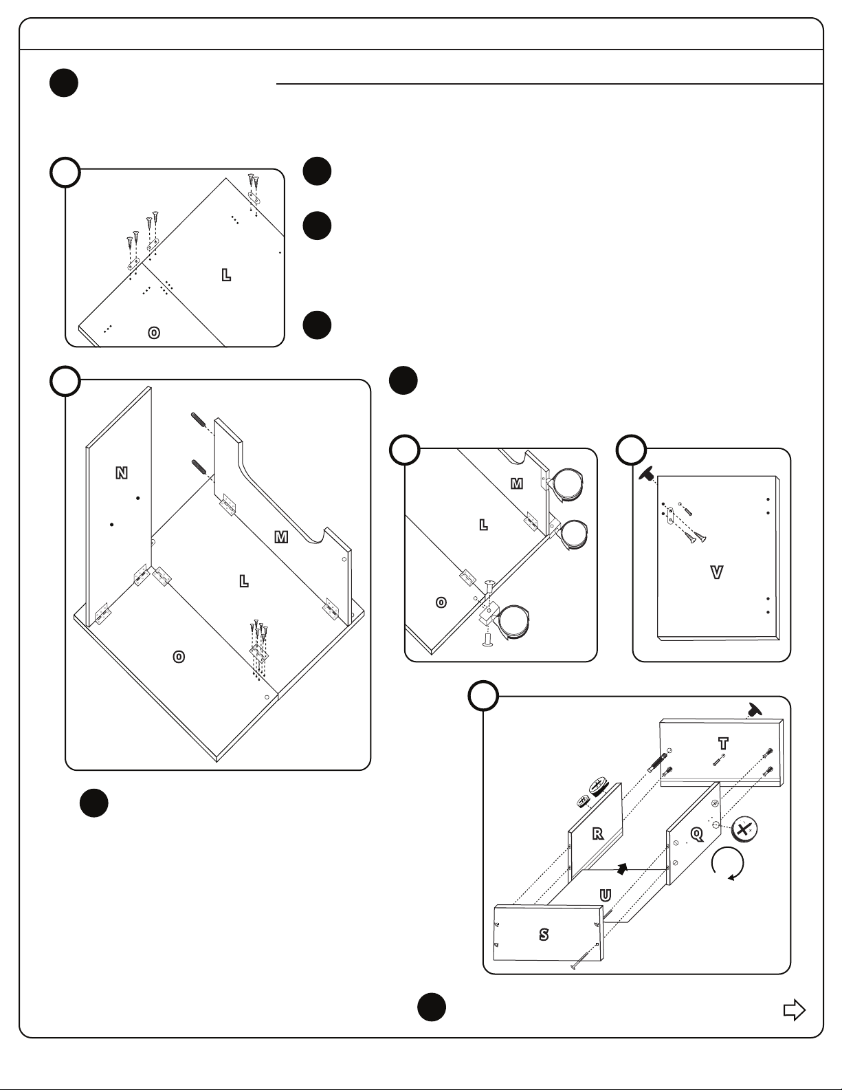
4DOORS & DRAWER
Parts Needed: L, M, N, O, Q, R, S, T, U, V, #1-(60), #3-(4), #5-(3), #7-(6), #12-(4), #13-(4), #14-(3),
#15-(2), #17-(4), #19-(3), Phillips Screwdriver (not included)
4A Use 6 Screws (#1) and Screwdriver to attach 3 Metal Covers (#17) to Right
Door Panel (L) and to Right Door Panel (O) as shown.
Use 12 Screws (#1) and a Screwdriver to attach 2 Hinges (#7) to connect Right
Door Panel (O) and Right Door Panel (L). Use 12 Screws (#1) and 2 Hinges (#7)
to connect Support Panel (M) to Right Door Panel (L). Insert 2 Plugs (#15) into
Support Panel (M). Use 12 Screws (#1) and 2 Hinges (#7) to connect Top Panel
(N) to Right Door Panel (O).
4B
4C Use 3 Screws (#5) to install 3 Locking Casters (#19) onto the Right Door Panel
(O), Right Door Panel (L), and Support Panel (M).
Use 2 Screws (#1) to attach 1 Metal Cover (#17) to Left Door
Panel (V). Separate knob and screw to install 1 Handle (#14),
with the knob on the other side of Left Door Panel (V).
4D
4A
4B
#17
#1
#1
#15
#7
4C
4E
4D
4DOORS & DRAWERS (CONTINUED)
#1
#17
#14
#14
Screw 4 Cam Bolts (#12) into Front Drawer Panel (T) with
Screwdriver. Separate knob and screw to install 1 Handle
(#14), with knob on other side of Front Drawer Panel (T).
Insert 2 Cam Locks (#13) each into outside of Side
Drawer Panels (Q & R). Connect Side Drawer Panels (Q &
R) with Cam Bolts on Front Drawer Panel (T) and twist
Cam Locks clockwise with Screwdriver to lock. Slide
Drawer Bottom Panel (U) into grooves on bottom of two
Side Drawer Panels (Q & R) and Front Drawer Panel (T).
Align the groove (on other side) of Back Drawer (S) then
use 4 Screws (#3) and Screwdriver to attach it to
Side Drawer Panels (Q & R) as shown.
4E
#12
#13
#13
#3