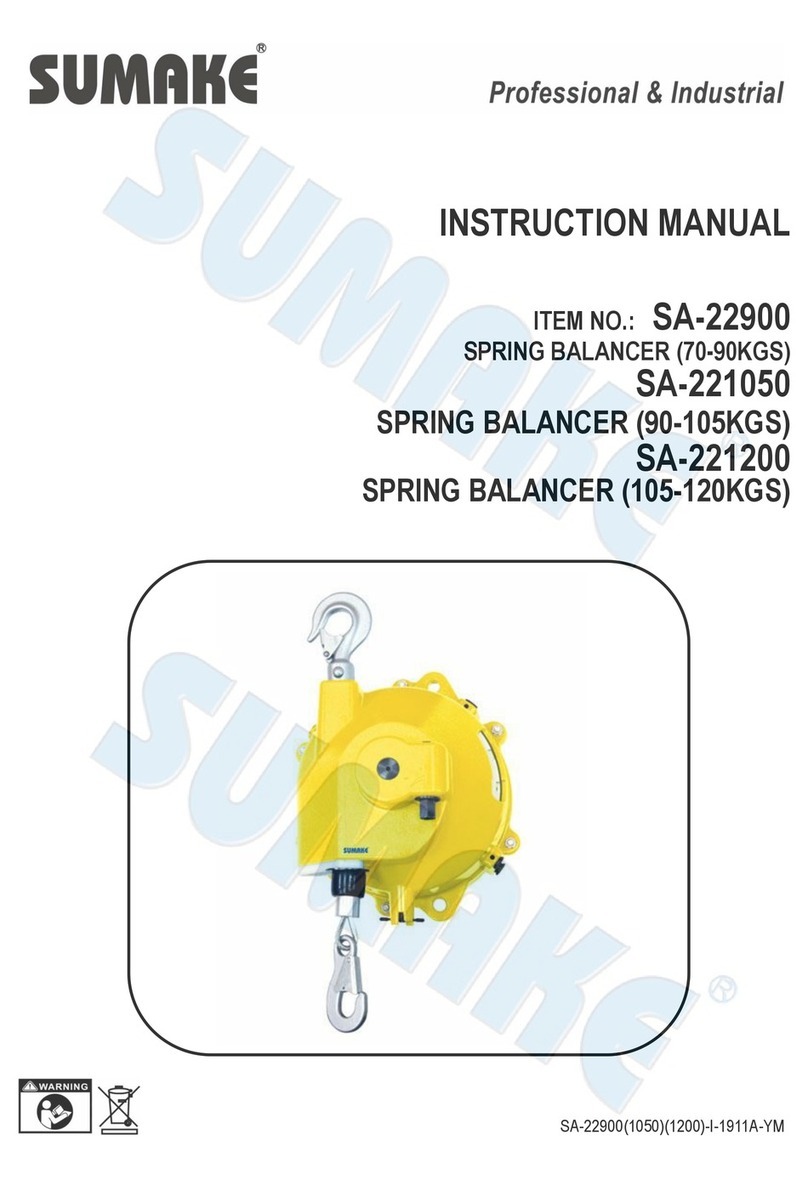
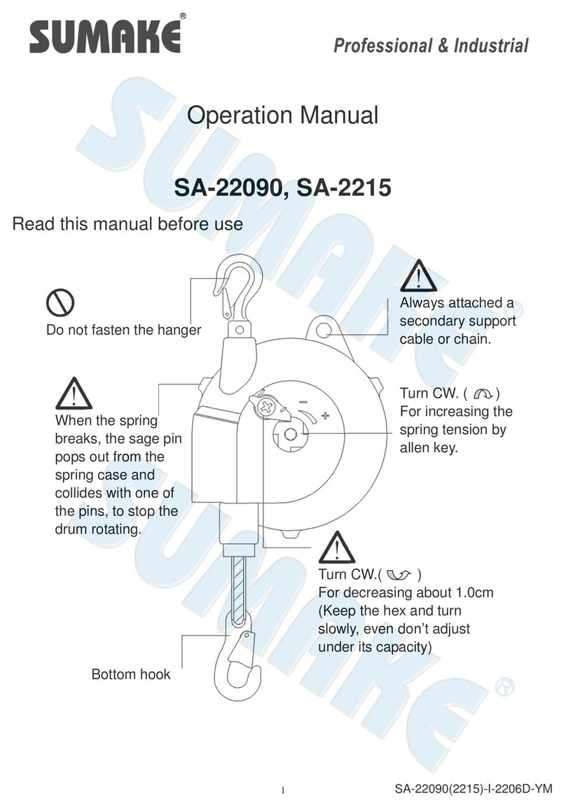
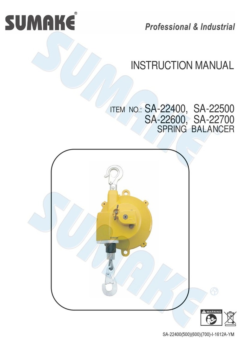
Sumake SA-22015T8 User manual

INSTRUCTION MANUAL
ITEM NO.: SA-22015T8, SA-22025T8
SA-22035T8, SA-22050T8
SA-22065T8
SPRING BALANCER
SA-22015(25)(35)(50)(65)T8-I-2206B-YM

1
1. Safety instructions on use
Incorrect use of the spring balancer could cause
personal injury.
Observe instruction in the manual and use the
balancer correctly.
Never stand under the spring balancer.
Be careful to disassembly.
Never put the spring balancer in fluid.
Caution
Prohibition

2
Don’t twist and rub the cordage with cable during
travel.
Don’t load over its capacity.
1. Take the suspended tools off while remove the spring balancer, prevent the devise drop down.
2. Please remove the spring balancer and tools if rest for a long time.
3. Remove the spring balancer and devise before arranging the tension.
Large angle using will debase the wire rope's life,
Under ±20∘is better.

3
Leave some slack in the secondary support cable or
chain to allow the balancer to rotate freely.
The slack must be a suitable length so that the
balancer will stop within 10cm when falling in case of
failure of the hanger or the fitting.
2. Description of product
(1) Specifications
Model
Capacity
Net Weight
Travel
Hose I.D.
SA-22015T8
0.5 - 1.5 kg
1.9 kg
1.3 m
8 x12
SA-22025T8
1.5 - 2.5 kg
2.0 kg
1.3 m
8 x12
SA-22035T8
2.5 - 3.5 kg
2.1 kg
1.3 m
8 x12
SA-22050T8
3.5 - 5.0 kg
2.1 kg
1.3 m
8 x12
SA-22060T8
5.0 - 6.5 kg
2.2 kg
1.3 m
8 x12
(2) Working conditions
Application area:
In door and atmospheric conditions
Operating temperature:
-10 ℃~ +40 ℃
Application fluid:
Air
Maximum air pressure:
1.0 Mpa (10 kgf/cm²)
3. Installation
⚫Install the balancer correctly, incorrect installation could cause personal injury or
damage to the balancer or other equipment
⚫Always attach a secondary support cable or chain. This is required to protect
personnel in case of failure of the hook or the fitting.

4
(1) Attach the joint to balancer and connect the air supplying hose to the joint (Fig-1)
NOTE: Leave some slack in the hose to allow the balancer to rotate freely.
(2) Prepare a fitting that can support at lest 10 times the maximum capacity of the balancer.
NOTE: The fitting must have no opening to prevent the balancer from disengaging when it swings.
(3) Please attached a second dry support cable that can bear 10 times the capacity of balancer.
(4) Attach the top hook of the balancer directly to the fitting check the latch is closed.
NOTE: Take care the balancer does not hit surrounding objects
(5) Install the suitable tool to the swivel joint.
(6) Please adjust the tension within the capacity after install the devise.
4. Checks before use
(1) The hanger and swivel joint is steady and turn flexile.
(2) Check the hose is complete and the travel is long enough to the application.
NOTE: Extending the hose past the maximum hose travel could damage the balancer.
(3) The appearance is complete, no any damage
5. Spring tension adjustment.
(1) Adjust the tension by turning the worm with a wrench, turn "+" side (clockwise) to increase the spring
tension, turn "-" side (counterclockwise) for decreasing. (see Fig.2)
NOTE: If the tension set over maximum capacity of balancer, the balancer or hose will be damaged.
6. Tool device replacement
⚫Shut off the air supply and release the pressure in the hose before staring replacement
⚫Never remove the suspended tool/device while the hose is extended. If removed, the hose
will snap back and could cause personal injury .

5
(1) Only removing the suspended tool/device when the hose is fully retracted.
(2) Attach a new tool/device and then adjust spring tension according to Items “5”Spring tension
adjustment ".
7. Troubleshooting.
⚫If a malfunction occurs during operation, stop operation immediately and take the necessary
steps to rectify the problem.
⚫Never remove the suspended tool/device until the cause of malfunction is explicated.
(1) Common malfunctions and their causes
Malfunction
Cause
Solution
Hose cannot be pulled out and
retracted.
Spring has broken.
Spring replacement.
[See Chapter 9-(2)]
Hose cannot be pulled out.
Spring is fully wound up
because of over tensioning.
Fall prevention device is
engaged because the spring
tension is set under the
minimum capacity.
Spring tension adjustment.
[See Chapter 5-(1)]
Release fall prevention device.
[See Chapter 7-(2)]
*** Contact your dealer or us if a malfunction not listed above occurs.
(2) Solutions
⚫Careless repairs can cause personal injury or damage to the balancer. There fore, be careful when
making repairs.
⚫Never remove the suspended tool if prevention device has engaged. Or the hose will snap back when
prevention device disengages and could personal Injury.
⚫The fall prevention device has engaged when the spring tension is set under the minimum
capacity.
⚫While suspending the tool/device, turn worm gear "+"side (clockwise) to increase the spring tension
until the fall prevention device disengages. [See Chapter 5-(1)]
8. Inspections
⚫Periodically inspect the balancer, and replace any worn or damaged parts.
NOTE: Always use genuine parts for replacement.
⚫Inspect the balancer at least once a month. Correct and repair any problems which are
detected.

6
⚫Make the inspection interval short the when operating frequently or under hostile
environments.(See Fig3)
Fig-3
(1) Inspect the accessories if they are correctly fixed and replace the worn parts.
(2) Check the latch if it is becoming deformed.
(3) Make sure the shaft is moving freely and stably.
(4) The casing should be no broken or damage.
(5) Swivel joint should be without leaking and loosing.
(6) Auxiliary support cable should be working properly.
(7) No worn or damage.
(8) The screws are tightly fixed without damage.
(9) Check the buffer is no damage.
(10) No broken or worn around the hose.
9. Pars replacement
⚫Shut off the air supply and release the pressure in the hose before staring replacement.
⚫Never remove the suspended tool/device while the hose is extended.
(1) Hose and O-ring replacement.
Referring to the parts list drawing, replace the hose and the o-rings using the following procedure.

7
A. Remove the air supplying hose from joint.
B. Lift then remove the tool/device from Swivel Joint(#31) when Hose(#24) is fully retracted into
Drum(#20).
C. Remove the balancer from the fitting or the supporting member and place on the table.
D. Remove joint while fastening copper Joint(#33) by a wrench.
E. Remove type E Snap(#7) from Worm Gear(#8)
F. Release all spring tension by turning Worm Gear(#8) to the "-"side (counterclockwise) until worm can
almost be removed.
NOTE: Check the spring tension by pulling hose.
G. Turn Worm(#8) further and remove it.
H. Loosen Screw(#38)and remove Cover(#37).
I. Remove Drum(#20), Copper Joint(#33), Joint(#21), Hose(#24) and Worm Wheel(#12) all together
from Casing(#10).
J. Remove worm Wheel(#12) form Drum(#20).
K. Slide Rotary Joint(#21) to "D" direction until joint stops. (see Fig-5)
L. Remove Copper Joint(#33), Rotary Joint(#21) and Hose(#24) all together from Drum(#20). (See
Fig-4).
M. Loosen Hose Clip(#23) and disconnect Hose(#24) from Rotary Joint(#21).
NOTE: Processed the following procedure with care not to slide joint to "C" direction.
N. Remove O-Ring(A) shown in (See Fig-4) Then remove Joint(#21) from Cooper Joint(#33) and
remove O-Ring(B).
NOTE: Do not remove Washer(#32) from Copper Joint(#33).
O. Reassemble in reverse order.
a. Take care of the assembling direction and position of hose Clip(#23) relating to Joint(#21). (See
Fig-7)
NOTE: Tighten hose clip securely by using a socket wrench. Never use a screw driver to tightening
Hose clip. Otherwise tightening torque is insufficient and Hose will come out from Joint.
b. O-Rings(#22)
(a) Attach new O-Ring(B) shown in Fig-4 into a groove of Copper Joint(#33) and lubricate with
grease.(See Fig-6)

8
*** Use lithium saponified silicom grease corresponding to the No.2 class of the NLGI (Nat.
lubrication Grease Just).
(b) Attach Joint(#21) on Copper Joint(#33) and push until Joint(#21) touches the washer (see Fig-5).
(c) Attach new O-Ring(A) shown in Fig-4 into the other groove of Copper Joint(#33) and lubricate with
grease.
c. Attach Copper Joint(#33), Joint(#21) and Hose(#24) all together into Drum(#20).
NOTE: If Hose Clip(#23) collides with Drum(#20),rotate Hose clip a little.
P. Push Copper Joint(#33) until it is stopped by Drum(#20). Then move Joint(#21) until it touches
Drum(#20), moving Joint to "C" direction.
Q. Wing Hose(#24) into Drum(#20) and mount Worm Wheel(#12) with Drum and then install in
Casing(#10).
R. Reassemble removed parts in reverse order of steps A to H
(2) Spring disposal
⚫Never remove the spring from the drum unless the replacement is required.
⚫The spring is extremely dangerous. Be Careful when handling the spring.
⚫Never pull the center of the spring when removing the spring from the drum. If pulled, the
spring will expand explosively and cause personal injury.
⚫Referring to the disassembly drawing, replace the spring using the following procedure.
A. Remove Drum(#20) from Casing(#10) and then remove Copper Joint(#33), Joint(#21) and Hose(#24)
all together from Drum in accordance with the procedure 9-(1),Hose and O-ring replacement, 9-A to
9-L.
B. Remove Screw(#17) and then spring Cover(#18).
C. Check where is the broken portion of spring(#19).
(a) Check that the rivet of spring(#19) is not broken.
(b) If Spring is broken near the outer preiphery where there is no space between each turn or the rivet of
Spring(#19) is broken (see Fig-8), stop the replacement work. Reassemble Cover(#18) and contact
the dealer.

9
⚫Never remove Spring(#19) from Drum(#20) when Spring(#19) is broken near the outer
periphery or the rivet of spring is broken (see Fig-8). If removed, Spring(#19) will expand
explosively and cause personal injury.
D. Remove Spring(#19) from Drum(#20).
E. Reassemble in reverse order
(a) After assembling new Spring(#19) lubricate Spring(#19)with grease.
(b) When installing Cover(#18) on Drum(#20),please Baffle(#16) in the outer edge of Spring(#19). Check
Baffle(#16) can move smoothly after inst ailing Cover(#18). (see Fig-8)
F. Wind Spring(#19) by turning Worm(#8) to the"+" side (clockwise) After Hose is fully retracted, turn
Worm by the number of turns shown in Table.1.
Table 1
Model
SA-22015T8
SA-22025T8
SA-22035T8
SA-22050T8
SA-22060T8
No of Turns
Approx 120
Approx 75
Approx 70
Approx 65
Approx 85
G. Adjust the spring tension according to Chapter 5-(1).
10. Broken Spring disposal
◆The spring is danger due to remaining tension even if it is broken.
◆Give warning to disposal companies that the spring will explosively and cause
danger if the spring is treated or the center of the spring is pulled.

ECDECLARATION OF CONFORMITY
We: SUMAKE INDUSTRIAL CO., LTD.
4F, No. 351, Yangguang St., Neihu District, Taipei City, Taiwan
declare in sole responsibility that the equipment
Equipment:SPRING BALANCER
Model/ Serial No.:SA-22015(22025)(22035)(22050)(22065)T8
to which this declaration applies, complies with these normative documents:
Machinery Directive: 2006/42/EC
and conforms to the following EN standard,
EN ISO 12100: 2010
Name and Signature/Position Date and Place
2013/2/22
MikeSu–ManagingDirector Taipei, Taiwan
SA-22015(25)(35)(50)(65)T8-D-1504A-YMF

SA-22015T8 SPRING BALANCER
(
0.5-1.5KG
)
SA-22025T8 SPRING BALANCER
(
1.5-2.5KG
)
SA-22035T8 SPRING BALANCER
(
2.5-3.5KG
)
SA-22050T8 SPRING BALANCER
(
3.5-5.0KG
)
SA-22060T8 SPRING BALANCER
(
5.0-6.5KG
)
PARTS LIST
No. Parts No. Description Q't
y
No. Parts No. Description Q't
y
6 SA22015T8-06 N
y
lon Nut 5
7 SA22015T8-07 T
y
pe E Rin
g
1
8 SA22015T8-08 Worm Gear 1
9 SA22015T8-09 Waher 1 21 SA22015T8-21 Rotar
y
j
oint 1
12 SA22015T8-12 Worm Wheel 2 22 SA22015T8-22 O-Rin
g
2
17 SA22015T8-17 Screw 125 SA22015T8-25 Rubber 1
32 SA22015T8-32 Copper Joint Washer 1
33 SA22015T8-33 Copper Joint 1
34 SA22015T8-34 Screw 1
35 SA22015T8-35 Washer 1
36 SA22015T8-36 Safet
y
Rin
g
Handle [Imcl. 37] 1
38 SA22015T8-38 Screw 1
40 SA22015T8-40 Worm Washer 1
SA-22015
(
25
)(
35
)(
50
)(
65
)
T8-P-1510B-YM
Spring Plate Set [Incl. 19, 20]
[SA-22015T8]
Spring Plate Set [Incl. 19, 20]
[SA-22025T8]
Spring Plate Set [Incl. 19, 20]
[SA-22035T8]
Spring Plate Set [Incl. 19, 20]
[SA-22050T8]
1
1
1
1
1
Casing Set [Incl. 1, 2, 3, 4, 5,
10, 11]
Spring Cover Set [Incl. 13, 14,
15, 16, 18(3)] Swivel Joint Hose Set [Incl. 23,
24, 26, 27, 28, 29, 30(3), 31]
SA22015T8-2424
19 &
20
SA22015T8-01
SA22015T8-18
1
18
19 &
20
1
1
SA22015T8-19
SA22025T8-19
SA22035T8-19
SA22050T8-19
1
Spring Plate Set [Incl. 19, 20]
[SA-22065T8]
SA22065T8-19
This manual suits for next models
4
Table of contents
Other Sumake Lifting System manuals
Popular Lifting System manuals by other brands

Clarke
Clarke CML6 User instructions

Ingersoll-Rand
Ingersoll-Rand BHD15 instruction manual

Custom Equipment
Custom Equipment PS-1030 Operation & safety manual

Vestil
Vestil CYL-P-LUG Series instruction manual

HADEF
HADEF 27/12-EX Installation, Operating and Maintenance Instruction

LiftSmart
LiftSmart MLI Parts and service manual

LGMG
LGMG A30JE Maintenance manual

Columbus McKinnon
Columbus McKinnon Yale HTP Series Translated Operating Instructions

Maxon
Maxon RAILGATE RCM-1250 C Maintenance manual

Woodhead
Woodhead Aero-Motive BF Series Service manual

Ravaglioli
Ravaglioli KP442 E DUO manual

Equiptec
Equiptec Monkey MX21 Assembly manual