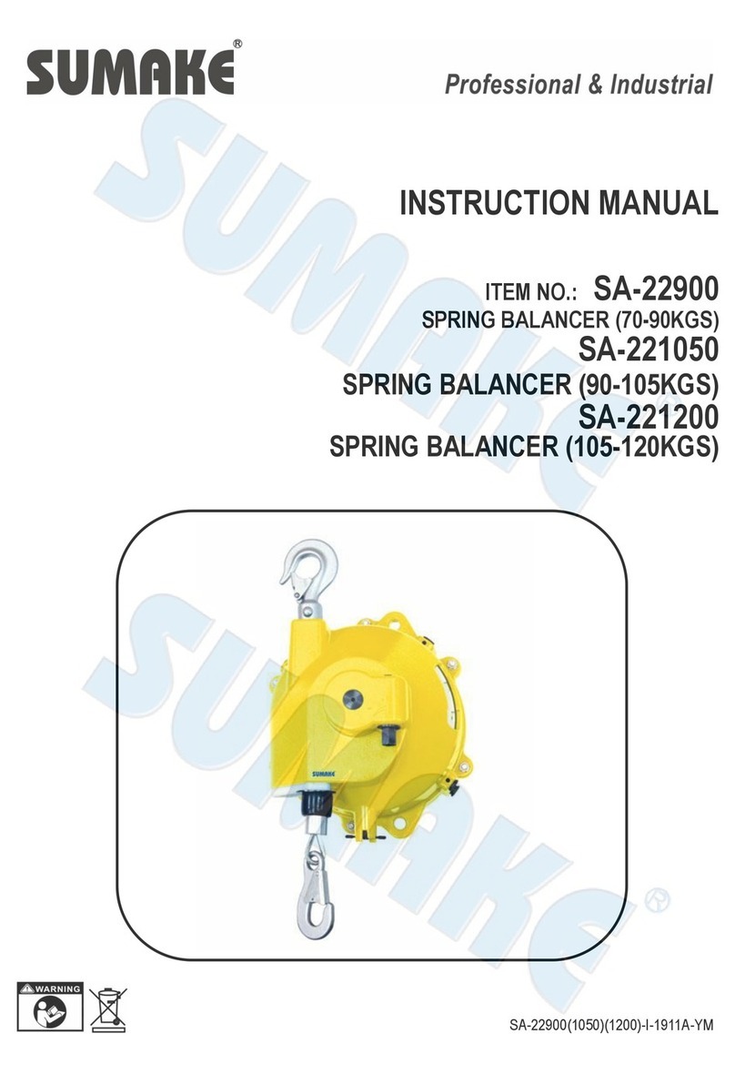
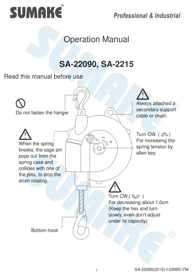
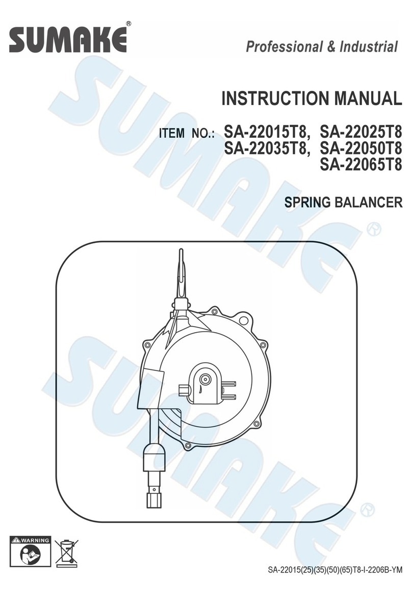
Sumake SA-22400 User manual

INSTRUCTION MANUAL
ITEM NO.: SA-22400, SA-22500
SA-22600, SA-22700
SPRING BALANCER
SA-22400(500)(600)(700)-I-1612A-YM

1
1. Safety instructions
Never stand under spring balancer Incorrect use of the spring Balancer could cause
personal injury.
Observe instruction in the manual
and use the balancer correctly.
Never put the spring balancer In fluid.
Don’t twist and rub the cordage with cable during travel.
Don’t load over its capacity.

2
Take the tools off while remove the spring balancer, prevent the devised drop down.
Please remove the spring balancer and tool if rest for a long time.
Large angle using will debase the wire rope’s life, under ±20° is better.
Never remove device while the wire rope is extend or the rope will retract immediately and cause personal injury.
Leave some slack in the secondary support cable or chain to allow the balancer to rotate freely.
The slack must be a suitable length so that the balancer will stop within 10cm when falling in case of failure of the hanger
or the fitting.

3
2. Description
2-1 Specification
Model No. Capacity (Kg) Travel (M) Weight (Kg)
SA-22400 30-40 1.5 9.7
SA-22500 40-50 1.5 10.1
SA-22600 50-60 1.5 11.1
SA-22700 60-70 1.5 11.4
2-2 Working condition
Application area: indoor
Temperature range: -10℃to 50℃
2-3 Mechanism Feature
Drop prevention device:
To prevent the suspended tool drop from Maximum cable travel in case of spring breakage. The safety pin will
pop out to stop the drum rotating if spring broken.
※ This device CAN’T prevent suspended tool from dropping when spring broken.
Drum lock: (refer to chapter 6-1 “Drum Lock Operation”
It will lock the drum per every 1/6 turns.
This mechanism is used to remove the suspended tool (refer to chapter 7)
or replace wire rope (refer to chapter 10)
or replace wire guide set ( refer to chapter 12).
3. Installation
Please install the spring balancer correctly, the incorrect installation will cause Perso personal injury or other equipment
damaged.
※Please must install secondary cable or chain. It’s to protect operator in case of damaged of top hanger.
3-1 Prepare the fitting which can bear at least 10 times the maximum capacity of spring balancer.
NOTE: The fitting must be closed to prevent the balancer disengaging or dropping.
3-2 Check whether the latch is in closed condition after installing.
NOTE: The spring balancer does not hit surrounding objects.
3-3 Chen whether the hanger can swivel.
NOTE: Please DO NOT fasten the hanger to the balancer body.
3-4 Prepare a secondary cable or chain that can bear at least 10 times maximum capacity of spring balancer.
3-5 Connect an end of secondary cable or chain to safety ring of balancer, and connect the other end to the stable
position.
3-6 Install the tool which is in capacity of spring balancer on hook.
3-7 Please adjust the spring tension after installing tool.

4
4. Check before using
4-1 The hanger and hook is stable and turn swivel.
4-2 The cable set is completed and no any damaged.
4-3 The stop pin is in open position. (see Fig.1)
4-4 The appearance is no any damage.
5. Spring TensionAdjustment
※If the spring tension is set over maximum capacity, the spring Balancer can’t provide specified cable travel and the
spring life will be shorted. If the spring tension is set under minimum capacity, the drop prevention device will operate
and stop the suspended tool.
5-1 Please use wrench to adjust spring tension by turning worm gear.
Turn clockwise is to increase (+) spring tension; turn counter-clockwise is to reduce (-) spring tension and the gauge
will show current approximate spring tension (see Fig.2)
5-2 Lift the tool up to hook and attach it. Never pull the cable down to tool.
5-3 Please re-check spring tension is fit after attaching tool.
5-4 Check the travel of spring balancer enough for application.
If necessary, please lower the mounting height or insert the suitable fitting between hook and suspended tool.

5
6. Drum Lock Operation
6-1 Pull the stop pin (No. 13) and turn clockwise to lock position
And move the tool upward or downward until drum become locked.
6-2 Move the tool again to check the drum is locked securely then remove tool from hook.
※Please check whether the stop pin is in lock position before removing suspended tool.
※If the drum is not in lock position then the cable will retract back immediately and may cause personal injury.
6-3 If operator needs to remove old suspended tool, please attach new tool before releasing drum lock.
6-4 Please pull the stop pin (No.13) up then turn counter-clockwise then place it in release position.
※Please DO NOT release drum lock if spring balancer unload or the weight of new tool is different with old tool.
If release it, the cable will retract back immediately or the tool will drop down respectively to cause personal injury.
※For safety consideration, please adjust spring tension to fit suspended tool before releasing drum lock.
7. Tool/device Replacement
▉Method No.1--- By drum lock
(1) According chapter 6” Drum Lock Operation’, operator can remove suspended tool when stop pin in lock potion.
※The operator can move tool upward and downward to check drum is locked securely.
※If drum is not locked securely, the cable will retract back immediately and cause personal injury.
(2) Please check the weight of new tool with all accessories is in capacity of spring balancer before attaching.
(3) Please use wrench to adjust spring tension by turning worm gear.
Turn clockwise is to increase (+) spring tension; turn counter-clockwise is to reduce (-) spring tension and the gauge
will show current approximate spring tension (see Fig.2)
(4) Please release stop pin after attaching new tool.
※Please DO NOT release drum lock before adjusting spring tension, if spring balancer unload or the weight of new tool
is different with old tool. If release it, the cable will retract back immediately or the tool will drop down respectively to
cause personal injury.
(5) Please re-adjust the spring tension after attaching new tool and release stop pin.
NOTE: If set spring tension over maximum capacity may cause spring balancer or cable set damaged.

6
▉Method No.2--- Don’t use stop pin of drum
※Never remove suspended tool when cable is extended. Or the cable will retract back immediately to cause personal
injury.
(1) The cable need to be retracted totally if operator needs to replace suspended tool.
(2) Please adjust spring tension according chapter 5 ”Spring Tension Adjustment” when attach the new tool.
8. Troubleshooting
※Please stop operating if malfunction occur during operation immediately and take the necessary step to check
problem.
※Please don’t remove suspended tool before finding causes for safety reason. If removed, the cable will retract back
immediately and cause personal injury.
8-1 Usual breakdown issue and causes:
Breakdown issue Causes Solution
●Cable can't pull or retract ●Drum lock
●Spring tension is under Min.capacity of
balancer so drop prevention device engage.
●The cable slipped off from drum and stuck
between drum and casing.●The spring
broken.
●Release drum lock (refer to chapter 6-4)
●Release drop prevention device (refer to
chapter 8-2)
●Make cable back to drum groove. (refer to
chapter 8-3)
●Replace spring set (refer to chapter 11-1)
※Please contact with distributor if the above problem occur.
※Careless repair may cause personal injury or spring balancer damaged, please be careful to repair.
8-2 Reason 1:
▉ Spring tension is under Min. capacity of balancer so drop prevention device engage. (see Fig.3)
(1) Move the suspend tool upward and downward by hand. The tool can move about 70-140mm.
If the tool rises after being lowered, turn worm gear (No. 3) counterclockwise until the tool start rising.
(2) Remove part No. 17 & 18 from Casing (NO. 1).
(3) Remove screw (No. 16) and all safety pin (No. 15) when carry hold the tool by hand.
※Operate this work by two persons for safety reason.
(4) Remove the tool when the wire rope is fully retract into drum set (No.5)
Check whether the tool weight is in capacity of spring balancer.
(5) Attach the stuff which weight is in capacity of spring balancer to hook then adjust the spring tension.

7
(6) Move the tool upward and downward so the safety pin appears in the hole for pin.
(7) Check whether the safe pin (No.33) bulb from the surface of ring (No.11); If protruding, tap the top of safe pin (No.33)
lightly by a Dia.5mm bar.
(8) If the safe pin can’t be retracted, it means the spring (No.12 /44) broken. Please disassembly spring set (No.7) from
casing (No.1), then release ring (NO.11), according to Chapter 11 ”Spring replacement”.
The spring (No.12/44) will pops out when release ring (No.11), please be careful to keep, avoid losing.
(9) The ring (No.11) needs reassembly after disassembly, and the surface of ring has to be level with spring set.
To avoid ring (No.11) from losing, please use little loctite on thread then assembly.
(10)Reassembly according to Chapter 11 “Spring Replacement” 11-13~11-18.
※If the installation of No.33 and No.15 is incorrect. Then the drop prevention device will not operate if spring broken,
then cause personal injury or equipment damaged.

8
8-3 Reason 2:
▉ When the wire rope stuck between drum and casing.
(1) To release the wire by pull strongly and quickly if the tool is suspended.
※Check the wire is damaged or not after pulling, please replace if damaged.
(2) Please disassembly if the wire can’t be release by pulling. Remove E snap (No.32) from worm gear (No.3).
(3) Turn worm gear (No.3) counterclockwise to release spring tension and remove it.
(4) Remove the tool from hook then remove spring balancer.
(5) Remove No.17 & 18 from casing (No.1).
(6) Remove screw (No.16) then release all safety pin (No.15)
(7) Release screw (No.36) and cover (No.9) after releasing gauge (No.37).
(8) Make the cable to the groove of drum (No.5).
※Check cable, replace it if damaged.
(9) Install the worm gear (No.3) and E snap (No.32).
(10)Adjust the spring tension and install gauge (No.37), safety pin (No.15), No.17 & 18. Please refer Chapter 11 “Spring
Replacement” 11-13~11-18.
9. Inspections
※Periodically inspect the spring balancer and replace the damaged part.
※Please must use the original part to replace.
▉ Inspect the spring balancer per month at least. Repair it if any problem detected. Please short the inspection interval
time if frequently operation or hostile environment. (Fig.4)

9
●Using limit of hook ●Using limit of cable
10.Cable Replacement
10-1 Pull the tool downward and extend the cable to Max. travel.
10-2According Fig.5, adjust the screw (No.27)
10-3 Move the tool upward and downward to make sure the drum is locked then remove tool from hook.

10
※Never remove the suspend tool before checking drum is locked securely.
※If drum is not locked securely, the cable may retract or the drum will rotate suddenly and possible to case personal
injury.
10-4 Remove the spring balancer from fitting and put on stable position.
10-5 Release screw (No.27) and pull out the old cable from drum, if upper cable stuck inside of drum, push the tip of cable
into the drum by a driver or others and try again. (see Fig.6)
10-6 Insert the new cable to from “A” to “B” hole and through drum. If can’t be through the drum cause cable stuck inside of
it, please press and twist. The cable will go through to drum by this method.
10-7 Install the end of cable to drum and fasten by screw (No.27).
10-8 Install the Spring Balancer to the suitable position and refer to chapter 3.
10-9 Install the tool to hook of spring balancer and release drum lock.
※Please don’t release drum lock before installing suspend tool. If released, the cable will be retracted suddenly then
cause personal injury.
11.Spring Replacement
※Please don’t remove spring from spring plate or the spring will expand explosively and cause personal injury.
※Replace the spring plate as whole set.
Refer to the drawing and disassemble the spring balancer accords the steps.
11-1 A. When spring broken.
●Double spring type: SA-22400, SA-22500, SA-22600, SA-22700
※SA-22400, SA-22500, SA-22600, SA-22700 has two springs, so some spring tension remains if one spring
broken, be careful when disassembly.
▉ Please refer to Chapter 6-1” Drum Lock Operation” and lock it then remove suspend tool from Hook.
B. If the spring is not broken completely, made the cable retract to drum (No.5) and remove tool from Hook.
11-2 Remove Spring Balancer from fitting and place on stable table.
11-3 Remove gauge.
11-4 Remove E snap(No.32) from Worm Gear (No.3), release spring tension by turning worm gear counterclockwise
until worm gear can be removed. Make sure there is no spring tension remaining if drum lock is activated, then
release drum lock.
NOTE: To check spring tension by pulling cable.
11-5 Turn the worm gear then remove.
11-6 Remove steel plastic set (No.17&18) from casing.
NOTE: The screw (No.19) is sealed to avoid looseness, please use new screw if removed.
11-7 Release screw (No.16) and all safety pin (No.15)
11-8 Remove screw (No.27) from drum (No.5) and old cable; push the tip of cable into drum by driver and try again.
see Fig.6

11
11-9 Remove cover (No.9)、Spindle (No.4)、spring plate(No.7) and drum (No.5) from casing.
11-10 Remove spindle (No.4)
11-11 Disassemble spring plate (No.7) and screw (No.31) & washer (No.30) of drum (No.5)
11-12 Disassemble spindle sleeve (No.29) from spring plate(No.7)
※Do not disassemble spring cover (No.28) from spring plate (No.7); If removed,the internal spring will pops out and
cause personal injury.
11-13 Assemble by opposite steps.
●Install the safety pin after adjusting spring tension and assembly by steps as below.
11-14 Install the steel plastic (No.17&18) to casing (No.1)
NOTE: The screw (No.19) is sealed to avoid looseness, please use new screw if removed. The suitable
torque range is 2.8~3.0Nm.
11-15 Turn worm gear clockwise to wind the spring.
NOTE: The cable will retract to drum if turn worm gear. Please note the cable don’t slip out from drum
groove. Turn worm by the number of turns as below after cable fully retract.
11-16 Install the stuff which weight is in capacity of spring balancer and adjust the spring tension.
11-17 Install the gauge and adjust.
11-18 Install the safety pin (No.15) to casing (No.1). refer to Fig.7, use the screw (No.16) to tighten safety pin (No.15).
※If installation of Safety Pins(15) is Incorrect 0or missed, the fall prevention device will not operate in case of spring
breakage, causing personal injury or damage to equipment.
Model No. Turns
SA-22400 105
SA-22500 95
SA-22600 115
SA-22700 90

12
12.Wire Guide Replacement
12-1 pull out the wire rope to the position which steel plastic set is available and lock drum with drum lock device
(refer to Fig.8)
12-2After confirming the drum lock is on work, moving a suspended tool to up and down and take off it.
Never remove the suspended tool before checking Drum is locked. If Drum is not locked securely, the drum lock will be
released allowing rope to snap back or drum to rotate suddenly. And possible to case personal injury.
12-3 Remove the balancer from a fitting and place on the table
12-4 Remove the screw (No.19) and steel plastic set (No. 17&18)
12-5 Install new steel plastic (17&18)
NOTE: Screw(No. 19) are sealed against looseness, please replace old one with new ones when removed.
Tighten the screw with torque 2.8-3.0Nm {28-30kgf.cm}
12-6 Install the Spring Balancer on a fitting.
12-7Attach the tool to bottom hook and release the drum lock.
Never release the drum lock before attaching the tool. If released, the rope will snap back and could cause personal injury.

SA-22400 SPRING BALANCER
(
30-40KGS
)
SA-22500 SPRING BALANCER
(
40-50KGS
)
SA-22600 SPRING BALANCER
(
50-60KGS
)
SA-22700 SPRING BALANCER
(
60-70KGS
)
PARTS LIST
No. Parts No. Description Q'ty No. Parts No. Description Q'ty
16 SA22400-16 Screw 4
17 SA22400-17 Steel Plastic Jack Set [Incl. 18] 1
3 SA22400-03 Worm Gear 1 19 SA22400-19 Screw 2
4 SA22400-04 Spindle 1 20 SA22400-20 Sheath 2
5 SA22400-05 Drum 1 26 SA22400-26 Bearing 2
Spring Plate Set [SA-22400] 27 SA22400-27 Screw 1
[Incl. 6(2), 7, 11, 28, 33, 44] 29 SA22400-29 Spindle Sleeve 1
Spring Plate Set [SA-22400] 30 SA22400-30 Spring Washer 10
[Incl. 6(2), 7, 11, 28, 33, 44] 31 SA22400-31 Screw 6
Spring Plate Set [SA-22400] 32 SA22400-32 Washer 1
[Incl. 6(2), 7, 11, 28, 33, 44] 34 SA22400-34 Rubber Stop 1
Spring Plate Set [SA-22400] 35 SA22400-35 Aluninum Head 1
[Incl. 6(2), 7, 11, 28, 33, 44] 36 SA22400-36 Screw 4
8 SA22400-08 Cable Set 1 SA22400-37 Gauge [SA-22400] 1
SA22500-37 Gauge [SA-22500] 1
SA22600-37 Gauge [SA-22600] 1
SA22700-37 Gauge [SA-22700] 1
38 SA22400-38 Screw 1
12 SA22400-12 Spring 1 41 SA22400-41 Shaft 1
13 SA22400-13 Stop Pin 1 42 SA22400-42 Worm Wheel Axis 1
14 SA22400-14 Spring Pin 1 43 SA22400-43 Key 1
15 SA22400-15 Safety Pin 4 SA-22400(500)(600)(700)-P-1612A-YM
SA22600-06S 1
SA22700-06S
1
1
SA22400-06S
SA22500-06S
Casing Assembly [Incl. 1, 2,
21, 22, 23, 24, 25]
1 SA22400-01S 1
1
6
37SA22400-09S 1
1
9SA22600-09S
Cover Assembly [SA-22400,
SA-22500] [Incl. 10]
Cover Assembly [SA-22600,
SA-22700] [Incl. 10]

ECDECLARATION OF CONFORMITY
We: SUMAKE INDUSTRIAL CO., LTD.
4F, No. 351, Yangguang St., Neihu District, Taipei City, Taiwan
declare in sole responsibility that the equipment
Equipment:SPRING BALANCER
Model/ Serial No.:SA-22400(500)(600)(700)
to which this declaration applies, complies with these normative documents:
Machinery Directive: 2006/42/EC
and conforms to the following EN standard,
EN ISO 12100: 2010
Name and Signature/Position Date and Place
2016/12/2
MikeSu–ManagingDirector Taipei, Taiwan
SA-22400(500)(600)(700)-D-1612A-YMF

NOTE
www.SUMAKE.com
www.AIRCOMPRESSOR.com.tw
This manual suits for next models
3
Table of contents
Other Sumake Lifting System manuals
Popular Lifting System manuals by other brands

Clarke
Clarke CML6 User instructions

Ingersoll-Rand
Ingersoll-Rand BHD15 instruction manual

Custom Equipment
Custom Equipment PS-1030 Operation & safety manual

Vestil
Vestil CYL-P-LUG Series instruction manual

HADEF
HADEF 27/12-EX Installation, Operating and Maintenance Instruction

LiftSmart
LiftSmart MLI Parts and service manual

LGMG
LGMG A30JE Maintenance manual

Columbus McKinnon
Columbus McKinnon Yale HTP Series Translated Operating Instructions

Maxon
Maxon RAILGATE RCM-1250 C Maintenance manual

Woodhead
Woodhead Aero-Motive BF Series Service manual

Ravaglioli
Ravaglioli KP442 E DUO manual

Equiptec
Equiptec Monkey MX21 Assembly manual