Sumake F18/50C User manual

SUMAKE PNEUMATIC TOOLS
18 Gauge 2 In 1 Air Nailer & Stapler
F18/50C
SUMAKE INDUSTRIAL CO., LTD
4F,NO.351,Yangguang St.,Neihu Di trict TAIPEI, TAIWAN, ZIP:114-91
F18/50C-S-1405B-AC

TOOL SPECIFICATIONS
MODEL OF TOOL .................................................................. F18/50C
TOOL LENGTH ....................................................................... 10.62" (270 mm)
TOOL HEIGHT ........................................................................ 9.84" (250 mm)
TOOL WIDTH .......................................................................... 2.32" (59 mm)
WEIGHT (WITHOUT F STENERS) ...................................…3.31 lbs (1.5 kg)
IR INLET ............................................................................... 1/4" NPT
COMPRESSED IR :
Maximum permissible operating pressure ............................. 110 PSIG (7.5 bar)
Recommended operating pressure range ........................….. 60 ~ 100 PSIG (4 ~ 7 bar)
IR CONSUMPTION.............................................................. 0.0172 scfm with 25
nails per minute
@ 100 psi (6.9 bar)
Noise dB( ):
-weighted sound pressure level Lp ……………….……….. 86.02 dB( )
-weighted sound power level Lw ………………….……..… 99.02 dB( )
Measurement uncertainty: 3dB
Vibration (m/s2 ):
Hand-arm vibration value…………………………………..….. 3.38 m/s2
Measurement uncertainty: 1.5 m/s2
Warning:
The vibration emission during actual use of the power tool can differ from the declared total
value depending on the ways in which the tool is used; and of the need to identify safety
measures to protect the operator that are based on an estimation of exposure in the actual
conditions of use (taking account of all parts of the operation cycle such as the times when
the tool is switched off and when it is running idle in addition to the trigger time).
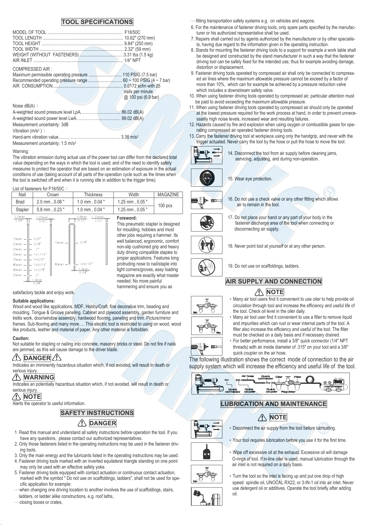
List of fasteners for F18/50C:
Nail
Crown
Thickness
Width
M G ZINE
Brad 2.0 mm , 0.08 " 1.0 mm , 0.04 " 1.25 mm , 0.05 " 100 pcs
Stapler
5.8 mm , 0.23 " 1.0 mm , 0.04 " 1.25 mm , 0.05 "
Foreword:
This pneumatic stapler is designed
for moulding, hobbies and most
other jobs requiring a hammer. Its
well balanced, ergonomic, comfort
non-slip cushioned grip and heavy
duty driving compatible staples to
proper applications. Features long
protruding nose to nail/staple into
tight corners/groves, easy loading
magazine are exactly what master
needed. No more painful
hammering and ensure you as
satisfactory tackle and enjoy work.
Suitable applications:
Wood and wood like applications, MDF, Hobby/Craft, fine decorative trim, beading and
moulding. Tongue & Groove paneling. Cabinet and plywood assembly, garden furniture and
trellis work, door/window assembly, hardwood flooring, paneling and trim. Picture/mirror
frames. Sub-flooring and many more…. This electric tool is restricted to using on wood, wood
like products, leather and material of paper. ny other material is forbidden.
Caution:
Not suitable for stapling or nailing into concrete, masonry bricks or steel. Do not fire if nails
are jammed, as this will cause damage to the driver blade.
DANGER
Indicates an imminently hazardous situation which, if not avoided, will result in death or
serious injury.
WARNING
Indicates an potentially hazardous situation which, if not avoided, will result in death or
serious injury.
NOTE
lerts the operator to useful information.
SAFETY INSTRUCTIONS
DANGER
1. Read this manual and understand all safety instructions before operation the tool. If you
have any questions, please contact our authorized representatives.
2. Only those fasteners listed in the operating instructions may be used in the fastener driv-
ing tools.
3. Only the main energy and the lubricants listed in the operating instructions may be used.
4. Fastener driving tools marked with an inverted equilateral triangle standing on one point
may only be used with an effective safety yoke.
5. Fastener driving tools equipped with contact actuation or continuous contact actuation,
marked with the symbol " Do not use on scaffoldings, ladders", shall not be used for spe-
cific application for example:
─when changing one driving location to another involves the use of scaffoldings, stairs,
ladders, or ladder alike constructions, e.g. roof laths,
─closing boxes or crates,
─fitting transportation safety systems e.g. on vehicles and wagons.
6. For the maintenance of fastener driving tools, only spare parts specified by the manufac-
turer or his authorized representative shall be used.
7. Repairs shall carried out by agents authorized by the manufacturer or by other specialis-
ts, having due regard to the information given in the operating instruction.
8. Stands for mounting the fastener driving tools to a support for example a work table shall
be designed and constructed by the stand manufacturer in such a way that the fastener
driving tool can be safely fixed for the intended use, thus for example avoiding damage,
distortion or displacement.
9. Fastener driving tools operated by compressed air shall only be connected to compress-
ed air lines where the maximum allowable pressure cannot be exceed by a factor of
more than 10%, which can for example be achieved by a pressure reduction valve
which includes a downstream safety valve.
10. When using fastener driving tools operated by compressed air, particular attention must
be paid to avoid exceeding the maximum allowable pressure.
11. When using fastener driving tools operated by compressed air should only be operated
at the lowest pressure required for the work process at hand, in order to prevent unnece-
ssarily high noise levels, increased wear and resulting failures.
12. Hazards caused by fire and explosion when using oxygen or combustible gases for ope-
rating compressed air operated fastener driving tools.
13. Carry the fastener driving tool at workpiece using only the handgrip, and never with the
trigger actuated. Never carry the tool by the hose or pull the hose to move the tool.
14. Disconnect the tool from air supply before cleaning jams,
servicing, adjusting, and during non-operation.
15. Wear eye protection.
16. Do not use a check valve or any other fitting which allows
air to remain in the tool.
17. Do not place your hand or any part of your body in the
fastener discharge area of the tool when connecting or
disconnecting air supply.
18. Never point tool at yourself or at any other person.
19. Do not use on scaffoldings, ladders.
AIR SUPPLY AND CONNECTION
NOTE
‧Many air tool users find it convenient to use oiler to help provide oil
circulation through tool and increase the efficiency and useful life of
the tool. Check oil level in the oiler daily.
‧Many air tool user find it convenient to use a filter to remove liquid
and impurities which can rust or wear internal parts of the tool.
filter also increase the efficiency and useful of the tool. The filter
must be checked on a daily basis and if necessary drained.
‧For better performance, install a 3/8" quick connector (1/4" NPT
threads) with an inside diameter of .315" on your tool and a 3/8"
quick coupler on the air hose.
The following illustration shows the correct mode of connection to the air
supply system which will increase the efficiency and useful life of the tool.
LUBRICATION AND MAINTENANCE
NOTE
‧Disconnect the air supply from the tool before lubricating.
‧Your tool requires lubrication before you use it for the first time.
‧Wipe off excessive oil at the exhaust. Excessive oil will damage
O-rings of tool. If in-line oiler is used, manual lubrication through the
air inlet is not required on a daily basis.
‧Turn the tool so the inlet is facing up and put one drop of high
speed spindle oil, UNOC L RX22, or 3-IN-1 oil into air inlet. Never
use detergent oil or additives. Operate the tool briefly after adding
oil.

LOADING THE TOOL
WARNING
‧Do not place your hand or any part of your body in the
fastener discharge area of the tool when connecting or
disconnecting air supply.
WARNING
‧Never point any operational fastener driving tool at
yourself or at any other person.
1. Disconnect air hose.
2. Depress the magazine latch. Pull back on the magazine
cover.
3. Insert a stick of fasteners into the
magazine. Make sure the pointed ends
of the fasteners are loaded with the
points downward. lso make sure
fasteners are not dirty or damaged.
4. Push the magazine cover forward until the latch
catches.
OPERATING THE TOOL
WARNING
Protect your eyes and ears. Wear z87.1 safety glasses with side
shields. Wear hearing protection. Employers and users are
responsible for ensuring the user or anyone near the tool wear this
safety protection.
NOTE
Check and replace any damaged or worn components on the tool.
The safety warning labels on the tool must also be replaced if they are
not legible.
1. dd a few drops of UNOC L RX22 or 3-in-1 oil into the air inlet.
(See Fig. 1)
2. ttach a high flow quick connect fitting to the tool. (See Fig. 2)
3. Empty the magazine.
4. Connect the tool to an air compressor using a 3/8" I.D hose.
Make sure the hose has a rated working pressure exceeding 200
PSI (13.8bar) and a female quick coupler. (See Fig. 3)
5. Regulate the air pressure to obtain 70 PSI (4.8 bar) at the tool.
(See Fig. 4)
6. Disconnect the air supply from the tool.
7. Load fasteners into your tool following the instructions in this
manual. (See Fig. 5)
8. Reconnect the air supply to the tool.
9. Test for proper fastener penetration by driving nails into a sample
piece of wood. If the fasteners do not achieve the desired
penetration, adjust the air pressure to a higher setting until the
desired penetration is achieved. Do not exceed 110 PSI (7.6 bar)
at the tool. (See Fig. 6)
CONTACT SAFETY TRIP MECHANISM
OPER TING CONT CT S FETY TRIP TOOL:
-The operator requires finger to be off the trigger and the nose
of the tool to be placed on the workpiece.
-The contact safety trip mechanism is then depressed against the
workpiece and the trigger is pulled to drive a fastener.
-The trigger is released after each fastener is driven.
-Move the tool to next location and the above procedure repeated.
CHECKING OPER TION OF CONT CT S FETY TRIP MECH NISM:
-Disconnect the air supply from the tool.
-Empty the magazine.
-Make sure the trigger and contact safety trip mechanism move up
and down without any sticking.
-Connect air supply to the tool.
-Depress the contact safety trip mechanism against the workpiece
without pulling the trigger. The tool must not cycle. Never use the
tool if a cycle occurs.
-Hold the tool clear of the workpiece. The contact safety trip
mechanism should return to its original down position. Pull the
trigger. The tool must not cycle. Never use the tool if a cycle
occurs.
-Depress the contact safety mechanism again the workpiece and
pull the trigger, the tool must cycle.
CLEARING A JAM FROM THE TOOL
WARNING
Disconnect the tool from air compressor before adjusting, clearing
jams, servicing, relocating and during non-operation.
1. Fastener jammed in fastener discharge area:
‧Disconnect tool from air hose.
‧Grab jammed fastener with pliers and remove.
2. Fastener jam inside magazine:
‧Disconnect air tool from air hose.
‧Pull back on fastener pusher until locked.
‧Removed jammed fastener.
‧Release fastener pusher.
CLEANING THE TOOL
DANGER
Never use gasoline or other flammable liquids to clean the tool. Va
pors in the tool will ignite by a spark and cause the tool to explode
and result in death or serious personal injury.
NOTE
Solvents used to clean the nose of the tool and contacr safety trip
mechanism may soften the tar on the shingles and cause the
buildup to be accelerated. Make sure to dry the tool thoroughly after
cleaning and before operating the tool again.
1. Disconnect the air supply from the tool.
2. Remove tar buildup with kerosene #2 fuel oil or diesel fuel. Do
not allow solvent to get into the cylinder or damage may occur.
Dry off the tool completely before use.
Fig.1
Fig.2
Fig.3
Fig.4
Fig.5
Fig.6

Description Spec Q'ty Description Spec Q'ty Description Spec Q'ty
CC0801 END CAP 1 FK0901 WORK CONTACTIN ELEMENT 1 OA024A O-RIN ARP568-024 1
CL2201 BUSHIN 1 FK1101 SUPPORT 1 OA127A O-RIN ARP568-127 1
FA4401 EXHAUST CAP 1 FK1201 SPRIN 1 OA131A O-RIN ARP568-131 1
FB0801 PUSHER PIN 2 FK1401 SAFETY CUSHION 1 OB021A O-RIN 1.8×1.2 2
FB0901 PUSHER SPRIN 2 FK1501 PLATE 1 OB031A O-RIN 3×1 1
FB2101 BODY 1 FK1601 C-RIN 1 OB221H O-RIN 21.5×3.0 1
FB2302 HEAD VALVE PISTON 1 FK1801 LATCH 1 OB323A O-RIN 31.8×2.4 1
FB2401 COMPRESSION SPRIN 1 FK1901 STOP PLATE 1 O 030A O-RIN 30 1
FB2501 PISTON STOP 1 FK2001 SAFETY 1 OP010A O-RIN P10 1
FB2601 CAP SEAL 1 FK2302 DRIVER SET 1 OP014A O-RIN P14 1
FB2801 COLLAR 1 FK2401 COMPRESSION SPRIN 1 OP025A O-RIN P25(1A) 1
FB2901 MAIN PISTON 1 FK2601 NOZZLE 1 UC1102 CONTACT LEVER 1
FB3104 CYLINDER 1 FY3601 COMPRESSION SPRIN 1 UC1603W TRI ER ASSY. 1
FB3201 PIN 1 KF0510 FLAT HD.BOLT M5×0.8-10L 1 UC4602 TRI ER 1
FB3301 BUMPER 1 KM0406 HEX.SOC.HD.BOLT M4×0.7-6L 3 UD1102W TRI ER VALVE ASSY. 1
FB3601 PISTON STOP 1 KM0410 HEX.SOC.HD.BOLT M4×0.7-10L 2 UD3601 TRI ER VALVE UIDE 1
FB3801 PISTON STOP 1 KM0412 HEX.SOC.HD.BOLT M4×0.7-12L 2 UD3701 TRI ER VALVE SEAT 1
FB7601 CYLINDER CAP 1 KM0412A HEX.SOC.HD.BOLT M4×0.7-12L 2 UD3802 TRI ER VALVE STEM 1
FE1201 EXHAUST CAP RIN 1 KM0516 HEX.SOC.HD.BOLT M5×0.8-16L 1 UD3901 COMPRESSION SPRIN 1
F 1001 BAR 1 KM0522 HEX.SOC.HD.BOLT M5×0.8-22L 2 UE1501 SEAL 1
FK0101-1 MA AZINE CAP (1) 1 KM0525 HEX.SOC.HD.BOLT M5×0.8-25L 4 UL4501 ADJUSTIN WHEEL 1
FK0101-2 MA AZINE CAP (2) 1 KS1606 SPRIN PIN ∮1.6-6L 1 Y 0401 SPRIN WASHER ∮4 1
FK0201 MA AZINE SEAT 1 KS2014 SPRIN PIN ∮2-14L 1 Y 0501 SPRIN WASHER ∮5 6
FK0301 UIDE PLATE 1 KS2506 SPRIN PIN ∮2.5-6L 1 YL0508 LOCK NUT M5×0.8 1
FK0303W DRIVER ASSY. 1 KS2514 SPRIN PIN ∮2.5-14L 1 #N/A #N/A 0
FK0401 FRONT PLATE 1 KS2524 SPRIN PIN ∮2.5-24L 2 #N/A #N/A 0
FK0502 COVER PLATE 1 KS3010 SPRIN PIN ∮3-10L 1 #N/A #N/A 0
FK0601 UIDE PLATE 1 KS3014 SPRIN PIN ∮3-14L 1 #N/A #N/A 0
FK0701 PUSHER 1 M 3201 SAFETY SET 1 #N/A #N/A 0
FK0801 COVER 1 OA003A O-RIN ARP568-003 1 #N/A #N/A 0
★☆ If you need to order parts, please mark both Parts No. and Description. ☆★
F18/50C 18 GAUGE 2 IN 1 AIR NAILER & STAPLER
Part_No Part_No Part_No
202107 a
B
C
B
C
A
A

EC DECLARATION OF CONFORMITY
We: SUMAKE INDUSTRIAL CO., LTD.
4F, No. 351, Yangguang St., Nei u District, Taipei City, Taiwan
declare in sole responsibility t at t e equipment
Equipment:18 Gauge 2 In 1 Air Nailer & Stapler
Model/ Serial No.: F18/50C
to w ic t is declaration applies, complies wit t ese normative documents:
Mac inery Directive: 2006/42/EC
and conforms to t e following EN standard,
EN ISO 12100: 2010
EN ISO 11148-13:2018
Name and Signature/Position Date and Place
2020/12/09
Mike Su – Managing Director Taipei, Taiwan
F18/50C-D-2107D-AC
Table of contents
Other Sumake Nail Gun manuals
Popular Nail Gun manuals by other brands

BluePoint Fasteners
BluePoint Fasteners GT-100L Safety & operation manual

North American Tool
North American Tool 7555 operating instructions

Paslode
Paslode PF250S-PP Operating manual and schematic

Aircat
Aircat 6265 Operating instructions, parts list & warranty

Senco
Senco FinishPro 18BL operating instructions

Maxus
Maxus MXN10400 Replacement parts manual