Sumake LMN-W40H User manual

SUMAKE PNEUMATIC TOOLS
3"X4" Air Orbital Non-Vacuum
Water Resistance Sander W/ Hook Pad
LMN-W40H
SUMAKE INDUSTRIAL CO., LTD
4F,NO.351,Yangguang St.,Neihu District TAIPEI, TAIWAN, ZIP:114-91
Specification:
Free Speed
10,000 r/min
Orbit Diameter
3 mm
Motor
0.24HP (179W)
Sanding Pad
3”x4”(76x101 mm)
Air Consumption
15 CFM (430 L/min)
Length
6.2” (158 mm)
Air Inlet (PT)
1/4” (6.35 mm)
Air Hose (I.D.)
1/4” (6.35 mm)
Air Pressure
90 psi (6.3 bar)
Net Weight
1.58 lbs (0.72 kg)
Noise and Vibration:
Vibration
EN ISO 28927-3
Noise
EN ISO 15744
Remark
Load:
3.94 m/s²
Sound Pressure Level
load: 83.5 dB(A)
Please always
wear ear
protector at
environment
noise level > 80
dB(A) due to
risk of impaired
hearing!
Sound power level
load: 94.5 dB(A)
Uncertainty
K= 1.5 m/s²
Uncertainty
K= 3dB
LMN-W40H-S-2002B-XPF

LMN(C)(G)-40(LMN-W40H)-P-2002C-XP
3"x4"(75x100MM) AIR ORBITAL NON-VACUUM WATER RESISTANCE SANDER W/ HOOK PAD
LMN-W40H
LMN-40H(V)
3"x4"(75x100MM) AIR ORBITAL NON-VACUUM SANDER, W/ HOOK(VINYL) PAD
LMC-40H(HM)
3"x4"(75x100MM) AIR ORBITAL CENTRAL-VACUUM SANDER, W/ HOOK(MULTIHOLE HOOK) PAD
LMG-40H(HM)
3"x4"(75x100MM) AIR ORBITAL SELF-GENERATED VACUUM SANDER, W/ HOOK(MULTIHOLE HOOK) PAD

PARTS LIST
No. Parts No. Description Q'ty No. Parts No. Description Q'ty
1 XPA0040 External Retaining Ring 1 42 XPA0076 Washer (M4) 4
2 XPA0021 Bearing -6000zz 1 43 XPC0018 Mini Pad Support Assembly (3"x4") 2
3 XPB0017 Rear Endplate 1 44 XPA0766 Hex Socket Countersunk Head Machine Screw (M4x6) 4
4 XPB0011 Cylinder Assembly 1 45 XPB0101 Machined 3x4" Pad Backing For Fastener Mounted Pads 1
5 XPA0042 O-Ring 1 46 XPA0767 Hex Socket Countersunk Head Machine Screw (M4x10) 4
6 XPB0005 Machined Rotor 1 47 XPA0078 Socket Flat Counter Sunk Machine Screw (M6x14) 1
7 XPA0010-1 Vane 5 48 NA 1 Pad Supplied With Each Tool OPT
8 XPA0041 Woodruff Key 1 49 XPA0008 Valve Stem Assembly 1
9 XPB0016 Front Endplate 1 50 XPA0015 Valve Sleeve 1
10 XPA0019 Bearing 1 51 HN2-04CA Hex. Nut (M4) 1
11 & 12 XP10 Lock Ring Assembly 1 52 S6-0430A Hex.Socket Button Head Screw (M4x30) 1
13 EOS41006 3x4 In. Cooling Fan 1 53 XPA0043 O-Ring (9x1.5mm) 1
14 EOS41007 3x4 In. Cooling Fan 1 54 XPG0044 Exhaust Chamber 1
15 XPA2541 Front Bearing Dust Shield 1 55 XPA2204 O-Ring (9.5x1mm) 1
16 XPB0102 3"x4"-1/8"Orbit Os Airshield Plus Shaft Balancer 1 56 XPA2484 O-Ring (24x1mm) 1
17 XPA0122 Filter Material 1 57 XPF0013 Muffler 1
18 XPA0121 Duckbill Check Valve 1 58 XPF0008 Muffler Cover 1
19 XPA0120 Valve Retainer 1 59 XPF0011 Muffler O8.5xO21xT6mm 1
20 XPA0107 Retaining Ring 1 60 XPF0012 O-Ring (O/R 20x1 N70) 1
21 XPA0161 Bearing 1 61 XPF0009 Exhaust Cap, Buffer 1
22 XPA0196 Spacer 1 62 XPF0010 Variable Exhaust 1
23 XPA0162 Bearing 1 63 XPA0009 Valve Seat 1
24 XPA0108 Spacer 1 64 XPA0007 Valve 1
25 XPA2543 Spindle Bearing Dust Shield 1 65 XPF0094 Valve Spring 1
26 XPA0126 Belleville Washer 1 66 XPG0011 End Cap 1
27 XPA0177 Retaining Ring 1 67 XPF0054 SUMAKE Logo -End Cap 1
28 XPB0063 Spindle 1 68 XPA0044 14.0x1.5 O-Ring 1
29 XPA0080 Spacer (0.4T) 1 69 XPA2475 Inlet Bushing Assembly Elite 1
30 XPA0079 Spacer (0.2T) 1 70 S6-0410A Hex.Socket Button Head Screw (M4x10) 3
31 XPG0068 Grip (Pms Black)(69mm) 1 71 XPG0067 3"x4" SGV Swivel Exhaust Fitting Assembly [LMG] OPT
32 S5-3006A Hex Socket Headless Set Screw (M3x6) 1 72 XPG0066 3"x4" CV Swivel Exhaust Fitting Assembly [LMC] OPT
33 XPF0103 Speed Control 1 73 XPF0107 Snap-In Vac Cover Plate 1
34 IRTW-007 Inverted Retaining Ring (In) 1 74 XPF0081 Snap-In Vac Cover Plate (NV) 1
35 XPF0105 O-Ring (4x1.5) 1 75 XPA0864 2.5mm Hex Wrench 1
36 XPF0104 Speed Control 1 76 XPA0778 1"/28mm Hose Seal 1
37 XPF0057 Lever For SUMAKE (1/8in. Orbit) 1 77 XPA0392 1" Vac Hose To 1"x1-1/2"Adaptor Coupling & Airline Assembly OPT
38 XPA0031 Lever Spring Pin 1 78 XPA0412 1" Vac Hose To Double Bag Fitting And Airline Assembly OPT
39 XPG0070 Machined Housing (No Brand) 1 79 XPA0468 Vacuum Bag 1
40 XPF0106 3"x4" Side Cover (Black) 2 80 XPC0109 Vacuum Bag Insert 1
41 XPA0768 Hex Socket Button Head Machine Screw (M4x12) 4 81 XPG0118 3"x4" Swivel Exhaust Fitting Assembly [LMN-W40H] OPT
LMN(C)(G)-40(LMN-W40H)-P-2002C-XP
LMN-W40H
3"x4"(75x100MM) AIR ORBITAL NON-VACUUM WATER RESISTANCE SANDER W/ HOOK PAD
LMN-40H(V)
3"x4"(75x100MM) AIR ORBITAL NON-VACUUM SANDER, W/ HOOK(VINYL) PAD
LMC-40H(HM)
3"x4"(75x100MM) AIR ORBITAL CENTRAL-VACUUM SANDER, W/ HOOK(MULTIHOLE HOOK) PAD
LMG-40H(HM)
3"x4"(75x100MM) AIR ORBITAL SELF-GENERATED VACUUM SANDER, W/ HOOK(MULTIHOLE HOOK) PAD

EC DECLARATION OF CONFORMITY
We: SUMAKE INDUSTRIAL CO., LTD.
4F, No. 351, Yangguang St., Neihu District, Taipei City, Taiwan
declare in sole responsibility that the equipment
Equipment: 3"X4" AIR ORBITAL NON-VACUUM WATER RESISTANCE SANDER
W/ HOOK PAD
Model/ Serial No.: LMN-W40H
to which this declaration applies, complies with these normative documents:
Machinery Directive: 2006/42/EC
and conforms to the following EN standard,
EN ISO 12100: 2010
EN ISO 11148-8:2011
Name and Signature/Position Date and Place
2022/7/1
Mike Su – Managing Director Taipei, Taiwan
LMN-W40H-D-2207B-XPF

INSTRUCTION MANUAL
ITEM NO.: LMN-40H(V)
3"x4"(75x100MM) AIR ORBITAL NON-VACUUM SANDER
W/ HOOK (VINYI) PAD
ITEM NO.: LMC-40H(HM)
3"x4"(75x100MM) AIR ORBITAL CENTRAL-VACUUM SANDER
W/ HOOK (MULTIHOLE HOOK) PAD
ITEM NO.: LMG-40H(HM)
3"x4"(75x100MM) AIR ORBITAL SELF-GENERATED VACUUM SANDER
W/ HOOK (MULTIHOLE HOOK) PAD
ITEM NO.: LMN-W40H
3"x4"(75x100MM) AIR ORBITAL NON-VACUUM WATER RESISTANCE SANDER
W/ HOOK PAD
LMN(C)(G)-40(LMN-W40H)-I-2002B-XP

1
Work Stations
The tool is intended to be operated as a hand held tool. It is always recommended that the tool be used when standing on a solid floor.
It can be in any position but before any such use, the operator must be in secure position having a firm grip and footing and be aware
that the sander can develop a torque reaction. See the section “Operating Instructions”.
Putting the Tool into Service
Use a clean lubricated air supply that will give a measured air pressure at the tool of 90 psig (6.2 bar) when the tool is running with the
lever fully depressed. It is recommended to use an approved 3/8 in. (10 mm) x 25 ft (8 m) maximum length airline. It is recommended
that an air filter, regulator and lubricator(FRL) be used as shown in Figure 1.
Do not connect the tool to the airline system without incorporating an easy to reach and operate air shut off valve. The air supply
should be lubricated. It is strongly recommended that in Figure 1 as this will supply clean, lubricated air at the correct pressure to the
tool. Details of such equipment can be obtained from your supplier. If such equipment is not used then the tool should be manually
lubricated
To manually lubricate the tool, disconnect the airline and put 2 to 3 drops of suitable pneumatic motor lubricating oil such as Fuji Kosan
FK-20, Mobil ALMO 525 or Shell TORCULA® 32 into the hose end (inlet) of the machine. Reconnect tool to the air supply and run tool
slowly for a few seconds to allow air to circulate the oil. If the tool is used frequently, lubricate it on a daily basis or lubricate it if the tool
starts to slow or lose power.
It is recommended that the air pressure at the tool be 90 PSI (6.2 Bar) while the tool is running so the maximum RPM is not exceeded.
The tool can be run at lower pressures but should never be run higher than 90 PSI (6.2 Bar). If run at lower pressure the performance
of the tool is reduced.
Operating Instructions
1. Read all instructions before using this tool. All operators must be fully trained in its use and aware of these safety rules. All service
and repair must be carried out by trained personnel.
2. Make sure the tool is disconnected from the air supply. Select a suitable abrasive and secure it to the back-up pad. Be careful and
center the abrasive on the back-up pad.
3. Always wear required safety equipment when using this tool.
4. When sanding always place the tool on the work then start the tool. Always remove the tool from the work before stopping. This
will prevent gouging of the work due to excess speed of the abrasive.
5. Always remove he air supply to the sander before fitting adjusting or removing the abrasive or back-up pad.
6. Always adopt a firm footing and/or position and be aware of torque reaction developed by the sander.
7. Use only correct spare parts.
8. Always ensure that the material to be sanded is firmly fixed to prevent its movement.
9. Check hose and fittings regularly for wear. Do not carry the tool by its hose; always be careful to prevent the tool from being
started when carrying the tool with the air supply
connected.
10. Dust can be highly combustible. Vacuum dust collection
bag should be cleaned or replaced daily. Cleaning or
replacing of bag also assures optimum performance.
11. Do not exceed maximum recommended air pressure. Use
safety equipment as recommended.
12. The tool is not electrically insulated. Do not use where
there is a possibility of coming into contact with live
electricity, gas pipes, water pipes, etc. Check the area of
operation before operation.
13. Take care to avoid entanglement with the moving parts of
the tool with clothing, ties, hair, cleaning rags, etc. If
entangled, it will cause the body to be pulled towards the
work and moving parts of the machine and can be very
dangerous.
14. Keep hands clear of the spinning pad during use.
15. If the tool appears to malfunction, remove from use
immediately
16. Do not allow the tool to free speed without taking
precautions to protect any persons or objects from the loss
of the abrasive or pad.

2
Back-Up Pads
SUMAKE 3 in. x 4 in. pads are perfectly mated for use on the low profile orbital sander. The molded urethane pads are constructed
from premium, industrial-quality materials
3”x 4”(75x100mm) Orbital Sander Service Instructions
NOTICE: To receive any expressed or implied warranty, the tool must be repaired by an authorized
The 3 in. x 4 in. Orbital Sander Service Instructions section provided is for use after completion of the warranty period.
DISASSEMBLY INSTRUCTIONS Changing Grips:
1. The Grip has two “tabs” that wrap around the body of the sander under the inlet and exhaust. With a small screwdriver pick out
one of the “tabs” of the Grip, and then continue to go underneath the grip with the screwdriver and pry the Grip off the sander. To
install a new Grip, hold the Grip by the tabs making them face outward, align the Grip and slide it under the Throttle Lever then
press the Grip down until it seats onto the top of the sander. Make sure the two “tabs” seat under the inlet and exhaust.
Motor Disassembly:
1. Remove the Pad from the machine by removing the four Screws. Lightly secure tool in a vise using the T-7 Soft Collar (Included in
AVA0486 Kit - See “Service Tools and Accessories”) or padded jaws with the bottom of the machine facing upward. Remove the
four Screws and then the Screw. Remove the Pad Backing but be careful to observe and collect the optional Spacer(s) found
between the Spindle Assembly and the Pad Backing.
2. Take the machine out of the vise and take off the Soft Collar. Remove the four Screws with the Washers from the Housing and
remove the Mini Pad Supports. Lightly re-secure the tool in a vise using the T-7 Soft Collar (Included in AVA0486 Kit - See
“Service Tools and Accessories”) or padded jaws with the Lock Ring facing upward.
3. Remove the Lock Ring with the T-6 Motor Lock Ring Wrench/Spindle Puller Tool (Included in AVA0486 Kit - See “Service Tools
and Accessories”). Remove the O-Ring from the Lock Ring and set it aside. The motor assembly can now be lifted out of the
Housing.
4. Remove the Retaining Ring from the groove in the Shaft Balancer and the O-Ring from the Cylinder.
5. Remove the Rear Endplate. This may require setting the Rear Endplate on a (AVA0416) Bearing Separator and lightly pressing
the shaft through the Bearing and Rear Endplate. the Shaft Balancer. Remove the Key then press off the Front Endplate with the
Bearing. It may be necessary to remove the Bearing with a (AVA0416) Bearing Separator if it came out of the Front Endplate and
stuck to the shaft of the Shaft Balancer.
6. Remove and discard Dust Shield from the Shaft Balancer.
7. Remove the Bearing(s) from the Endplates by using the T-8 Bearing Removal Tool (Included in AVA0486 Kit –See “Service Tools
and Accessories”) to press out the Bearings.
Shaft Balancer and Spindle Disassembly:
1. Grip the shaft end of the Shaft Balancer in a padded vise. With a thin screwdriver pick out the slotted end of the Retaining Ring
and peel out.
2. Screw the female end of the T-12 5/16-24 to M6 x 1P Adapter (Included in AVA0491 Kit - See “Service Tools and Accessories”)
into the male end of the T-6 Motor Lock Ring Wrench/Spindle Puller Tool (Included in AVA0486 Kit - See “Service Tools and
Accessories”). Screw the Service Wrench Assembly into the Spindle Assembly until hand tight. Apply a gentle heat from a
propane torch or hot air gun to the large end of the Shaft Balancer shaft until it is about 100°C (212° F) to soften the adhesive. Do
not over heat. Remove the Spindle Assembly by using the slider to give sharp outward blows to the Spindle. Allow the Spindle and
Shaft Balancer to cool.
Description
Screw-On, Non-Vacuum, Vinyl Face Pad
Screw-On, Non-Vacuum, Hook Face Pad
Screw-On, Non-Vacuum, J-Hook Face Pad
Screw-On, Standard Vacuum, Vinyl Face Pad
Screw-On, Standard Vacuum, Hook Face Pad
Screw-On, Standard Vacuum, J-Hook Face Pad
Screw-On, Screen Vacuum, J-Hook Face Pad

3
3. Remove the Retaining Ring from the Spindle Assembly. Use a (AVA0416) Bearing Separator to remove the Bearing, Shim,
Bearing, Shim, Dust Shield and the Washer from the Spindle Assembly. Discard Dust Shield.
4. The components are held in place by the light press fit of the retainer. These components can be damaged during removal and
may need to be replaced if removed. To remove the Retainer, use an O-ring pick or a #8 sheet metal screw to grip and pull out the
Retainer. Remove the Valve and Filter from the bore in the Shaft Balancer. If the Retainer and Valve were not damaged, they can
be reused. However, the filter should be replaced on re-assembly
Housing Disassembly:
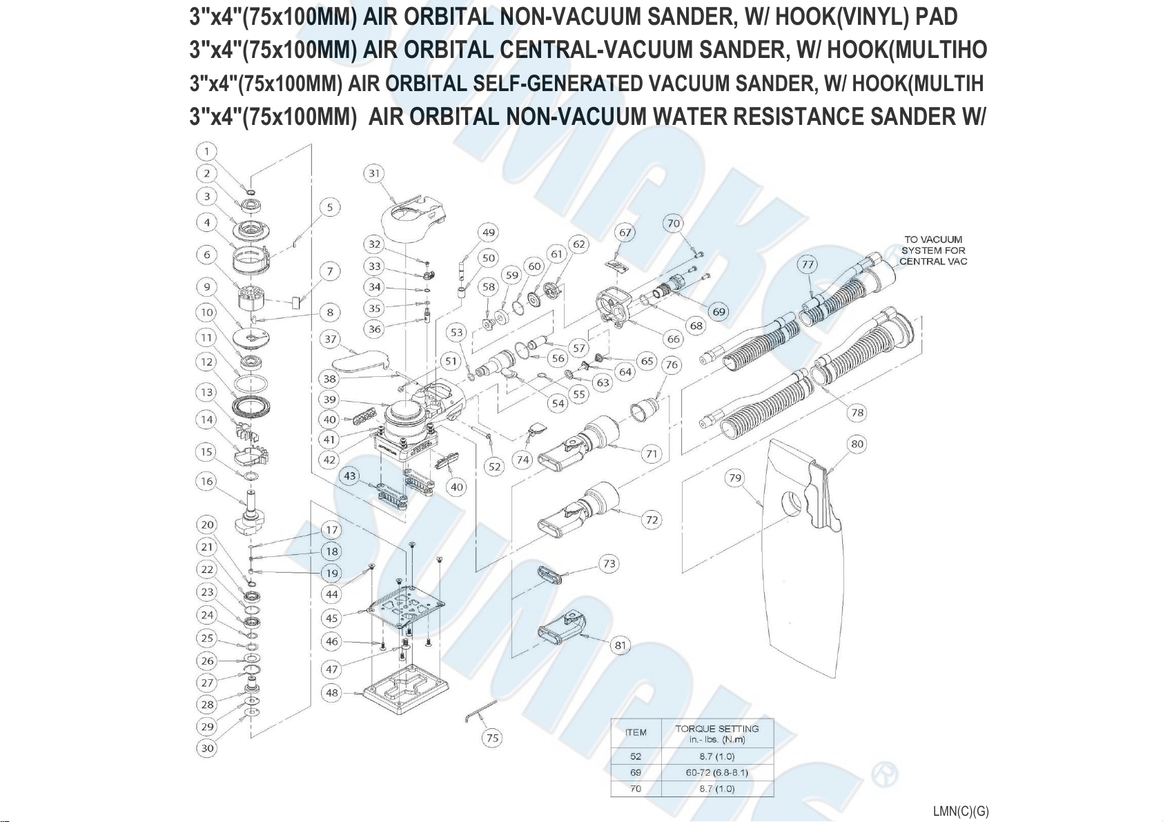
1. For Non-Vacuum (LMN-40H(V)/ LMN-W40H) and Central Vacuum (LMC-40H(HM)) machines follow steps A - C below (unless
otherwise noted). For Self Generated Vacuum (LMG-40H(HM)) machines disregard steps A - F and move onto Step G below.
A. Unscrew the muffler housing from the housing.
B. Remove the muffler from the cavity of the muffler housing
C. Remove the plate and second muffler from the exhaust port of the housing of the Housing.
For Central Vacuum (LMC-40H(HM)) Exhaust machines:
D. Remove the Screw, Washer and Nut.
E. Press downward on the swivel end of the Φ1in.(28 mm) CV Swivel Exhaust Assembly or the Φ3/4in.(19mm) CV Swivel Exhaust
Assembly releasing the tab on the end of the exhaust assembly from the Snap-In Exhaust Adapter.
F. Work off the Snap-In Exhaust Adapter. Move on to step 2.
For Self Generated Vacuum (LMG-40H(HM)) Exhaust machines:
G. Unscrew the SGV Retainer Assembly with an 8 mm hex key. Remove the two O-rings. Take off the Φ1in.(28 mm) SGV Swivel
Exhaust Assembly or the Φ3/4in.(19 mm) Hose SGV Swivel Exhaust Assembly.
H. Work off the Snap-In Exhaust Adapter.
2. Place the Speed Control to the midway position and remove the Retaining Ring. The Speed Control will now pull straight out.
Remove the O-Ring.
3. Unscrew the Inlet Bushing Assembly from the Housing. Remove the Valve Spring, Valve, Valve Seat, Valve Stem with the O-Ring.
Press out the Spring Pin from the Housing and remove the Lever.
ASSEMBLY INSTRUCTIONS
NOTE: All assembly must be done with clean dry parts and all bearings are to be pressed in place by the correct tools and procedures
as outlined by the bearing manufacturers.
Housing Assembly:
1. Install the Throttle Lever into Housing with the Pin.
2. Lightly grease O-Ring and place it on Speed Control. Install Valve Stem, O-Ring (cleaned and lightly greased) and insert the
Speed Control into Housing in the midway position. Install Retaining Ring.
CAUTION: Make sure the Retaining Ring is completely snapped into groove in the Housing.
3. Install the Valve Seat, the Valve and Valve Spring. Coat the threads of the Bushing Assembly with 1 or 2 drops of Loctite ™ 222 or
equivalent non-permanent pipe thread sealant. Screw the assembly into the Housing. See the “Parts Page” for torque settings.
Place a clean muffler and plate into the exhaust port of the Housing. Be careful not to lose the Plate and muffler out of the exhaust
before it is secured in one of the following steps.
NOTE: If the machine is a LMC-40H(V)/LMG-40H(V) model proceed with the appropriate vacuum exhaust assembly instructions,
otherwise move onto step 4.
For LMC-40H(HM) (Central Vacuum) Exhaust machines:
A. Attach the Snap-In Exhaust Adapter.
B. Take the Φ1in(28mm) CV Swivel Exhaust Assembly or the Φ3/4in.(19mm) CV Swivel Exhaust Assembly and put the “tongue” on
the male end of it into the female end of the Snap-In Exhaust Adapter. With the swivel end of the Exhaust angled towards the
ground work the “tongue” and male end into the female end of the Snap-In Exhaust Adapter by rotating the swivel end up and in at
the same time until it seats.
C. Thread the Screw into the mounting hole of the Φ1in.(28mm) CV Swivel Exhaust Assembly or the Φ3/4in.(19mm) CV Swivel
Exhaust Assembly and housing until the end of it is flush with the inside surface of the Housing. Place the washer and Nut into the
cavity of the Housing and thread the Screw into them until tight. Move onto step 4.
For LMG-40H(HM) (Self Generated Vacuum) Exhaust machines:
A. Attach the Snap-In Exhaust Adapter.
B. Lightly grease two O-rings and place them over the two grooves in the SGV Retainer Assembly. Slide the SGV Retainer Assembly
into the bore of the Φ1in.(28mm) SGV Swivel Exhaust Assembly or the Φ3/4in.(19mm) Hose SGV Swivel Exhaust Assembly.
C. Attach the SGV Swivel Exhaust Assembly to the exhaust port of the Housing by means of the SGV Retainer Assembly and by

4
taking the male end of the Swivel Exhaust Assembly and placing it into the female end of the Snap-In Exhaust Adapter. Screw the
SGV Retainer Assembly into the threaded exhaust port on the Housing with an 8 mm hex key. See the “Parts Page” for torque
settings. Move onto the section “Spindle and Balancer Shaft Assembly”.
4. Place a clean muffler in the muffler housing and screw the muffler housing into the exhaust port of the housing. See the “Parts
Page” for torque settings.
Spindle and Balancer Shaft Assembly:
1. Place the T-2A Spindle Bearing Pressing Tool Base (Included in AVA0491 Kit - See “Service Tools and Accessories”) onto the
spindle pocket facing upward. Place the Spindle into the spindle pocket with the shaft facing upward.
2. Place the Washer on the Spindle shaft with the curve of washer facing out so that the outside diameter of the washer will contact
the outer diameter of the Bearing. Place the Dust Shield onto the Spindle shaft. Lay the Shim on the shoulder of the Spindle.
Note: Be sure that the Dust Shield is past the shoulder where Spacer rests. Place the Bearing (one seal) on the Spindle with the
seal side toward the Washer.
NOTE: Make sure that both the inner and outer races of the Bearings are supported by the Bearing Press Tool when pressing
them into place. Press the Bearing onto the shoulder of Spindle using the T-2B Spindle Bearing Pressing Tool Top (Included in
AVA0491 Kit - See “Service Tools and Accessories”) as shown in Figure 3.
3. Place the Shim over the Spindle shaft and onto the face of the Bearing making sure it is on center. Press the (no seals/shields)
Bearing down using the T-2B Spindle Bearing Pressing Tool Top (Included in AVA0491 Kit - See “Service Tools and
Accessories”), being careful to make sure the Shim is still centered on the vertical axis of the Spindle shaft and Bearing. See
Figure 4. When the Spindle Assembly is done correctly, the Bearings will rotate freely but not loosely and the Shim can be
moved but will not slide or move by gravity.
4. Snap the Retaining Ring (not shown in Figure 3 or 4) onto the Spindle Assembly making sure it is completely snapped into the
groove.
5. Take the Filter and center it on the small bore that the original Filter was in before removal. With a small diameter screw driver or
flat-ended rod, press the filter into the bore until it is flat in the bottom of the bore. Place the valve into the bore so it is oriented
correctly, then press the Retainer into the bore until it is flush with the bottom of the bearing bore.
6. Apply a pin head size drop of #271 Loctite® or equivalent to the outside diameter of each of the bearings on the spindle
assembly. Spread the drop of bearing locker around the bearings until distributed evenly.
CAUTION: Only a very small amount of bearing locker is needed to prevent rotation of the bearing OD. Any excess will make
future removal difficult. Place the Spindle Assembly into the bore of the Shaft Balancer and secure with the Retaining Ring.
CAUTION: Make sure that the Retaining Ring is completely snapped into the groove in the Balancer shaft. Allow the adhesive to
cure.
Motor Assembly:
1. Place the Dust Shield onto the shaft of the Shaft Balancer.
2. Use the larger end of the T-13 Bearing Press Sleeve (Included in AVA0486 Kit - See “Service Tools and Accessories”) to Press
the front Bearing (with 2 Shields) onto the shaft of the Shaft Balancer.
3. Slide the Front Endplate with the bearing pocket facing down onto the Motor Shaft. Gently press the Front Endplate onto the front

5
Bearing using the larger end of the T-13 Bearing Press Sleeve (Included in AVA0486 Kit - See “Service Tools and Accessories”)
until the front Bearing is seated in the bearing pocket of the Front Endplate.
CAUTION: Only press just enough to seat the Bearing into the pocket. Over-pressing can damage the Bearing.
4. Place the Key into the groove on the Shaft Balancer. Place the Rotor on the Shaft Balancer, making sure that it is a tight slip fit.
5. Oil the Vanes with a quality pneumatic tool oil and place them in the slots in the Rotor. Place the Cylinder Assembly over the Rotor
with the short end of the Spring Pin engaging the blind hole in the Front Endplate.
NOTE: The Spring Pin must project 0.6in.(1.5mm) above the flanged side of the Cylinder.
6. Press fit the rear bearing (2 shields) into the rear endplate with the T-1B Bearing Press Tool Top (Included in AVA0486 Kit - See
“Service Tools and Accessories”). Make sure the T-1B Press Tool is centered on the O.D. of the outer race. Shaft Balancer using
the small end of the T-13 Bearing Press Sleeve (Included in AVA0486 Kit - See “Service Tools and Accessories”). The sleeve
should press only the inner race of the bearing.
IMPORTANT: The Rear Endplate and Bearing is pressed correctly when the Cylinder is squeezed just enough between the
Endplates to stop it from moving freely under its own weight when the shaft is held horizontal, but be able to slide between the
Endplates with a very light force. If the assembly is pressed to tightly the motor will not run freely. If the pressed assembly is to
loose, the motor will not turn freely after assembly in the Housing.
CAUTION: If the Rear Endplate assembly is “over-pressed” damage to the Front and Rear Endplate Bearings may result.
7. Secure the assembly by placing the Retaining Ring in the groove of the Shaft Balancer.
CAUTION: The Retaining Ring must be placed so that the middle and two ends of the hoop touch the bearing first. Both raised
center portions must be securely “snapped” into the groove in the Shaft Balancer by pushing on the curved portions with a small
screwdriver.
8. Lightly grease the O-Ring and place in the air inlet of the Cylinder Assembly.
9. Lightly grease or oil the inside diameter of the Housing, line up the Spring Pin with the marking on the Housing and slide the Motor
Assembly into the Housing. Make sure the Pin engages the pocket in Housing
10. Carefully screw the Lock Ring into the Housing with the T-6 Motor Lock Ring Wrench/Spindle Puller Tool (Included in AVA0486 Kit
- See “Service Tools and Accessories”). See the “Parts Page” for torque settings.
NOTE: A simple technique To assure first thread engagement is to turn the lock ring counter clockwise with the T-6 Motor Lock
Ring Wrench/ Spindle Puller while applying light pressure. You will hear and feel a click when the lead thread of the lock ring drops
into the lead thread of the housing.
11. Place one of the Mini Pad Support Assemblies into the Housing with the 45 degree chamfer of the base facing outward away from
the center of the machine and the arc in the base of the pad support facing toward the center of the machine. Screw tight with the
two Screws and Washers. Repeat for second pad support.
12. Using a straight edge placed across both bottom surfaces of the Mini Pad Support Assemblies, measure the distance from the
surface of the Spindle Assembly to the straight edge. There should be approximately .010 in. (0.25 mm) of space, if not add
supplied Spacers in the combination that most closely results in .010 in. (0.25 mm) of spacing.
NOTE: Spindle face must be slightly below Mini Pad Supports for best function. Do not over shim. Apply a small amount of anti-
seize compound in the 5-90° c’sink holes of the Pad Backing before assembly. Place the Pad Backing by orientating the Shims
with the screw holes and placing the pad backing down onto the Spindle Assembly making sure the pin goes through the pad
backing. Add the screw first and tighten firmly. In a circular rotation apply smaller screws into the Pad Backing and Mini Pad
Support Assemblies but leave them slightly loose until all are in place, and then tighten firmly.
13. Attach a new Pad on the Pad Backing with the four Screws.
Testing:
Place 3 drops of quality pneumatic air tool oil directly into the motor inlet and connect it to a 90 psig (6.2 Bar) air supply. The tool
should run between 9,500 and 10,500 Orbits per Minute when the air pressure is 90 psig (6.2 Bar) at the inlet of the tool while the tool
is running at free speed.

6
Troubleshooting:
Symptom
Possible Cause
Solution
Low Power and/or Low Free Speed
Insufficient air Pressure
Check air line pressure at the Inlet of the
Sander while the tool is running at free
speed. It must be 6.2 Bar (90 psig/ 620
kPa).
Blocked Muffler(s)
See the "Housing Disassembly" section for
Muffler removal. Replace muffler insert
(See the "Housing Assembly" Section)..
Plugged Inlet Screen
Clean the Inlet Screen with a clean,
suitable cleaning solution. If Screen does
not come clean replace it.
Worn or Broken Vanes
Install a complete set of new Vanes (all
vanes must be replaced for proper
operation). Coat all vanes with quality
pneumatic tool oil. See "Motor
Disassembly" and "Motor Assembly".
Internal air leakage in the Motor Housing
indicated
by higher than normal air consumption
and lower than normal speed.
Check for proper Motor alignment and Lock
Ring engagement. Check for damaged O-
Ring in Lock Ring groove. Remove Motor
Assembly and Re-Install the Motor
Assembly. See "Motor Disassembly" and
"Motor Assembly".
Motor Parts Worn
Overhaul Motor. Contact authorized
Service Center.
Worn or broken Spindle Bearings
Replace the worn or broken Bearings. See
"Shaft Balancer and Spindle Disassembly"
and "Spindle Bearings, and Shaft Balancer
Assembly".
Air leakage through the Speed Control
and/or Valve Stem.
Dirty, broken or bent Valve Spring, Valve or
Valve Seat.
Disassemble, inspect and replace wore or
damaged parts. See Steps 2 and 3 in
"Housing Disassembly" and Steps 2 and 3
in "Housing Assembly".
Vibration/Rough Operation
Incorrect Pad
Only use Pad Sizes and Weights designed
for the machine.
Addition of interface pad or other material
Only use abrasive and/or interface
designed for the machine. Do not attach
anything to the Sanders Pad face that was
not specifically designed to be used with
the Pad and Sander.
Improper lubrication or buildup of foreign
debris.
Disassemble the Sander and clean in a
suitable cleaning solution. Assemble the
Sander. (See "Service Manual")
Worn or broken Rear or Front Motor
Bearing(s)
Replace the worn or broken Bearings. See
"Motor Disassembly" and "Motor Assembly"
For central vacuum machines it is possible
to have too much vacuum while sanding on
a flat surface causing the pad to stick to the
sanding surface.
For LMC-40H(HM) machines reduce
vacuum through the vacuum system.

7
Safety Precautions
1. General safety rules:
⚫“Read and understand the safety instructions before installing, operating, repairing, maintaining, changing accessories on, or
working near the sander or polisher. Failure to do so can result in serious bodily injury.”
⚫“Only qualified and trained operators should install, adjust or use the sander or polisher.”
⚫“Do not modify this tool. Modifications can reduce the effectiveness of safety measures and increase the risks to the operator.”
⚫“Do not discard the safety instructions; give them to the operator.”
⚫“Do not use a sander or polisher if the tool has been damaged.”
⚫“Tools shall be inspected periodically to verify that the ratings and markings are legibly marked on the tool. The employer/user
shall contact the manufacturer to obtain replacement marking labels when necessary.”
2. Projectile hazards
⚫“Be aware that failure of the workpiece or accessories, or even of the inserted tool itself can generate high-velocity projectiles.
⚫”Always wear impact-resistant eye protection during operation of the sander or polisher. The grade of protection required should
be assessed for each use.”
⚫“For overhead work, wear a safety helmet.”
⚫“Ensure that the workpiece is securely fixed.”
3. Entanglement hazards
⚫“Choking, scalping and/or lacerations can occur if loose clothing, personal jewellery, neck wear, hair or gloves are not kept away
from the tool and its accessories.”
4. Operating hazards
⚫"Use of the tool can expose the operator's hands to hazards, including cuts and abrasions and heat. Wear suitable gloves to
protect hands."
⚫"Operators and maintenance personnel shall be physically able to handle the bulk, weight and power of the tool."
⚫"Hold the tool correctly; be ready to counteract normal or sudden movements and have both hands available."
⚫"Maintain a balanced body position and secure footing."
⚫"Release the start-and-stop device in the case of an interruption of the energy supply."
⚫"Use only lubricants recommended by the manufacturer."
⚫"Personal protective safety glasses shall be used; suitable gloves and protective clothing are recommended."
⚫"Inspect the backing pad before each use. Do not use if cracked or broken or if it has been dropped."
⚫"Avoid direct contact with the moving sanding pad in order to prevent pinching or cutting of hands or other body parts. Wear
suitable gloves to protect hands." workpiece."
⚫"There is a risk of electrostatic discharge if used on plastic and other non-conductive materials."
⚫"Potentially explosive atmospheres can be caused by dust and fumes resulting from sanding or grinding. Always use dust
extraction or suppression systems which are suitable for the material being processed."
5. Repetitive motions hazards
⚫"While using a sander or polisher, the operator should adopt a comfortable posture whilst maintaining secure footing and
avoiding awkward or off-balance postures. The operator should change posture during extended tasks; this can help avoid
discomfort and fatigue."
⚫"If the operator experiences symptoms such as persistent or recurring discomfort, pain, throbbing, aching, tingling, numbness,
burning sensations or stiffness, these warning signs should not be ignored. The operator should tell the employer and consult a
qualified health professional."
6. Accessory hazards
⚫"Disconnect the sander or polisher from the energy supply before fitting or changing the inserted tool or accessory."
⚫"Avoid direct contact with the inserted tool during and after use, as it can be hot or sharp."
⚫"Use only sizes and types of accessories and consumables that are recommended by the manufacturer of tool; do not use other
types or sizes of accessories or consumables.
⚫"Grinding wheels and cutting-off tools shall not be used."
⚫"Check that the maximum operating speed of the inserted tool (flap wheels, abrasive belts, fibre discs backing pads, etc.), is
higher than the rated speed of the tool."
⚫"Self-fixing sander discs shall be placed concentrically on the supporting pad."
8. Dust and fume hazards
⚫"Dust and fumes generated when using tool can cause ill health (for example cancer, birth defects, asthma and/or dermatitis);

8
risk assessment and implementation of appropriate controls for these hazards are essential."
⚫"Risk assessment should include dust created by the use of the tool and the potential for disturbing existing dust."
⚫"Operate and maintain the sander or polisher as recommended in these instructions, to minimize dust or fume emissions."
⚫"Direct the exhaust so as to minimize disturbance of dust in a dust-filled environment."
⚫"Where dust or fumes are created, the priority shall be to control them at the point of emission."
⚫"All integral features or accessories for the collection, extraction or suppression of airborne dust or fumes should be correctly
used and maintained in accordance with the manufacturer's instructions."
⚫"Select, maintain and replace the consumable/inserted tool as recommended in the instruction handbook, to prevent an
unnecessary increase in dust or fumes."
⚫"Use respiratory protection in accordance with employer's instructions and as required by occupational health and safety
regulations."
9. Noise hazards
⚫"Exposure to high noise levels can cause permanent, disabling hearing loss and other problems, such as tinnitus (ringing,
buzzing, whistling or humming in the ears). Therefore, risk assessment and implementation of appropriate controls for these
hazards are essential."
⚫"Appropriate controls to reduce the risk can include actions such as damping materials to prevent workpieces from “ringing”."
⚫"Use hearing protection in accordance with employer's instructions and as required by occupational health and safety
regulations."
⚫"Operate and maintain the sander or polisher as recommended in the instruction handbook, to prevent an unnecessary increase
in the noise level."
⚫"Select, maintain and replace the consumable/inserted tool as recommended in the instruction handbook, to prevent an
unnecessary increase in noise."
⚫"If the sander or polisher has a silencer, always ensure it is in place and in good working order when the tool is being operated."
10. Vibration hazards
⚫"Exposure to vibration can cause disabling damage to the nerves and blood supply of the hands and arms.”
⚫"Wear warm clothing when working in cold conditions and keep your hands warm and dry."
⚫"If you experience numbness, tingling, pain or whitening of the skin in your fingers or hands, stop using the sander or polisher,
tell your employer and consult a physician."
⚫"Operate and maintain the sander or polisher as recommended in the instruction handbook, to prevent an unnecessary increase
in vibration levels."
⚫"Hold the tool with a light but safe grip, taking account of the required hand reaction forces, because the risk from vibration is
generally greater when the grip force is higher."
11. Additional safety instructions for pneumatic power tools:
⚫"Air under pressure can cause severe injury: always shut off air supply, drain hose of air pressure and disconnect tool from air
supply when not in use, before changing accessories or when making repairs; never direct air at yourself or anyone else;"
⚫"Whipping hoses can cause severe injury. Always check for damaged or loose hoses and fittings;”
⚫"Whenever universal twist couplings (claw couplings) are used, lock pins shall be installed and whipcheck safety cables shall be
used to safeguard against possible hose-to-tool or hose-to-hose connection failure;” -"Do not exceed the maximum air pressure
stated on the tool;"
⚫"Never carry an air tool by the hose."
12. Operating instructions include, where appropriate:
⚫Instructions for setting up or fixing tool in stable position as appropriate if type of tool can be mounted;
⚫Assembly instructions, including recommended guards, accessories and inserted tools;
⚫An illustrated description of functions;
⚫Limitations on tool use due to environmental conditions;
⚫Instructions for setting and testing;
⚫General instructions for use, including changing inserted tools and limits on size and type of workpiece;
⚫Instructions stating that a tool shall not be operated at a speed exceeding the rated speed
www.SUMAKE.com
www.AIRCOMPRESSOR.com.tw
Table of contents
Other Sumake Sander manuals

Sumake
Sumake ELSC-50H(V) User manual

Sumake
Sumake LSN-W30H User manual

Sumake
Sumake ST-AS15N2R-S User manual

Sumake
Sumake ST-M5061S User manual

Sumake
Sumake LSC-60HM-8 User manual

Sumake
Sumake ST-AS10N3H-3 User manual

Sumake
Sumake ST-BS112G User manual

Sumake
Sumake ST-BS110B User manual

Sumake
Sumake ST-7117DC-5 User manual

Sumake
Sumake ELSC-B50H User manual

Sumake
Sumake ST-AS11N1H User manual

Sumake
Sumake EMC-B40H User manual

Sumake
Sumake ST-7110DC(S)-5 User manual

Sumake
Sumake EP-1800 User manual

Sumake
Sumake ST-7139DC-653 User manual

Sumake
Sumake LSC-30H User manual

Sumake
Sumake ST-M5060 User manual

Sumake
Sumake ST-BS110A User manual

Sumake
Sumake LSG-50HM-2.5 User manual

Sumake
Sumake ST-AS10N2H-3 User manual