Foreword
SUMAKE is a manufacturer and exporter of air
tools since established. We have devote all our
efforts in improving quality and tools’ life. As
well as the noise and vibration of tools. Bring all
of you working efficiences, profits, and enjoy
using the tool is our principle.
Features
1. Finishing of flat surfaces, curved surfaces, and
corner can be freely performed by changing the
shoe.
2. Since it is small, lightweight, and balanced so
that the grinding surface is stable, extremely fine
finishing is possible.
3. The grinding speed can be freely adjusted by
raising or lowing the lever according to the
application.
4. Rear exhaust eliminates flying dust and noise.
Operator‘s instruction
1. Main Applications
Finishing metal carts and products.
Finishing welded surface.
Trimming parts.
Filleting.
Finishing steel cabinets and furniture.
Foundation finishing prior to coating.
Finishing plastic products, glass, and
earthenware.
Finishing stone and decorative wood products.
Finishing sashes and other building material.
Light and medium duty auto, ship and aircraft
finishing.
2. Cautions for Use
2-1 Air pressure
Maximum performance is displayed at the proper
sanding speed, obtainable at a gauge pressure of
6.2 bar. Range-wise, this is an air pressure from
5 to 7 bar (70 to 100 psi)
57
2-2 Air line
Use a 3/8“ air hose between the compressor an
the tool . Compressed air is cooled and its wate
content separated, as soon as the air leaves th
compressor. A portion of the water content
however, is condensed in the piping, and ca
enter the tool mechanism, and may cause trouble
So, install an air filter and on oiler between th
compressor and the tool. Use a 3 HP or large
compressor for each sander.
Tool
Nipple
Coupler Recoil
hose
Leader
hose
Oiler Regulator
Water
separation Air
supply
Drain
daily
2-3 Air hose
Clean the hose with a blast of compressed ai
efore connecting the hose to air tool. This wil
prevent both moisture and dust within the hos
from entering the tool and causing possible rus
or malfunction. To compensate for unusuall
long hose (over 25 ft), the line pressure should b
increased accordingly.
Drainage
2-4 Sandpaper
The specification of sandpaper ranges from # 4
to # 200. Also note that, the maximum operatin
speed which the sandpaper can afford shall b
higher than the rotation speed of this tool.
2-5 The approved eye protector,ear-muff
mouth-muffle, and gloves shall be worn whe
operate this tool.
2-6 The working place shall be ventilative.
2-7 Release the on-off device in the case o
energy supply failure.
3. Operation, Adjusting And Replacing
Method
3.1 On-off device
The on-off device is under the grip of this tool. It
is a “hold-to-run” type. You can also adjusting
the running speed by raising or lowering the lever.
This tool stops rotation within few sec, after
releasing the lever. For the sake of safety, put it
on a soft cloth or on hanger after it completely
stops.
3.2 Replace the sandbelt
Disengage and remove the sandbelt from the idle
ulley after pushing the idle pulley in the
direction shown below. Replace a new one and
keep your hand away from the idle pulley. Then
ush the tension bar indicated on the drawing and
the sandbelt will be propped into the ready
osition.
idle pulley tension bar
3.3 Adjusting tracking
If the sandbelt is not centered on the idle pulley,
adjust the hexagon socket head bolt on the idle
ulley bracket with accessory hexagon wrench
key until centering is correct. Turn the hexagon
socket counter clockwise, the belt is moved
toward the bracket, and vice versa.
clockwise
counterclockwise
bracket
4. Maintenance
4-1 Lubrication
Before connecting the hose , apply 4 or 5 drops
of #60 spindle oil at the air inlet. Use of a thicker
oil can lead to reduced performance or
malfunction. If a
thicker oil is used by accident, wash it away
immediately. Also, every 3 or 4 hours of
operation, oiling is necessary.
4-2 Storage
Avoid storing the tool in a location subject to
high humidity. If the tool is left as it is used , the
residual moisture inside the tool can cause rust.
Before storing and after operation, oil the tool a
the air inlet with spindle oil and run it for a short
4-3 Disposal
If the tool is too seriously damaged to be use
anymore, drop it in a resource recycling can.
Never drop it into fire.
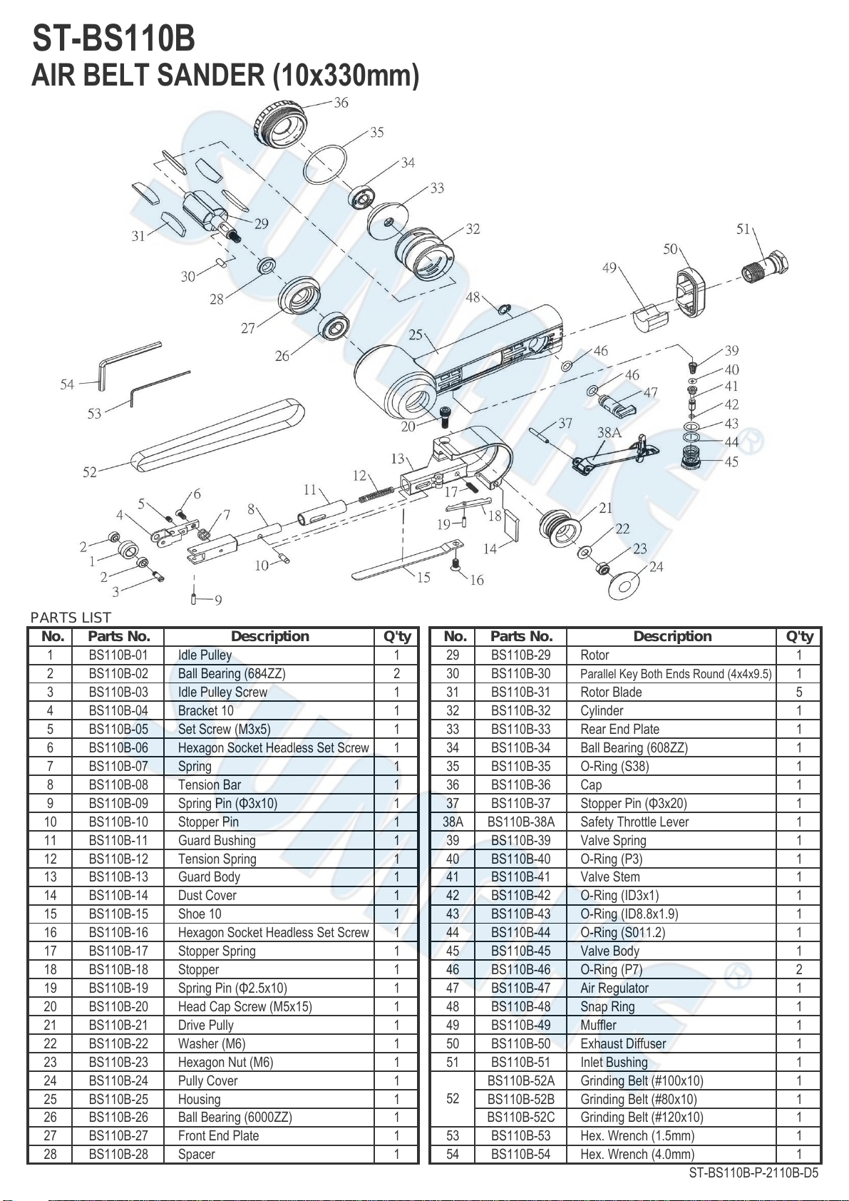
4-4 Ordering service Parts
For further operational and handling informatio
or for replacement of parts and components,
contact the sale agent from whom you purchase
the tool or the service division of our company.
*In ordering parts and components, give each
part number, name and quantity.
Warning
1. This tool is not insulted for coming into
contact with electric power source.
2. It is forbidden to use this tool in explosive
atmospheres and do not put any combustible
material near the workpiece since it emit sparks
when grind with metal material.
3. Ensure that the sandbelt is on the central o
idle pulley and not to fix too tight/loose. Too
tight tends to break off and too loose tends to
break away.
4. Prevent long hair or loose clothing fro
drawing in while operate this tool.
5. Never carry the tool by hose and beware of
whipping compressed air hose.
6. Rotating action can cause this tool to become
hot. Allow to cool and disconnect air hose before
any changing or adjusting.
Foreword
SUMAKE is a manufacturer and exporter of air
tools since established. We have devote all our
efforts in improving quality and tools’ life. As
well as the noise and vibration of tools. Bring all
of you working efficiences, profits, and enjoy
using the tool is our principle.
Features
1. Finishing of flat surfaces, curved surfaces, and
corner can be freely performed by changing the
shoe.
2. Since it is small, lightweight, and balanced so
that the grinding surface is stable, extremely fine
finishing is possible.
3. The grinding speed can be freely adjusted by
raising or lowing the lever according to the
application.
4. Rear exhaust eliminates flying dust and noise.
Operator‘s instruction
1. Main Applications
Finishing metal carts and products.
Finishing welded surface.
Trimming parts.
Filleting.
Finishing steel cabinets and furniture.
Foundation finishing prior to coating.
Finishing plastic products, glass, and
earthenware.
Finishing stone and decorative wood products.
Finishing sashes and other building material.
Light and medium duty auto, ship and aircraft
finishing.
2. Cautions for Use
2-1 Air pressure
Maximum performance is displayed at the proper
sanding speed, obtainable at a gauge pressure of
6.2 bar. Range-wise, this is an air pressure from
5 to 7 bar (70 to 100 psi)
57
2-2 Air line
Use a 3/8“ air hose between the compressor an
the tool . Compressed air is cooled and its wate
content separated, as soon as the air leaves th
compressor. A portion of the water content
however, is condensed in the piping, and ca
enter the tool mechanism, and may cause trouble
So, install an air filter and on oiler between th
compressor and the tool. Use a 3 HP or large
compressor for each sander.
Tool
Nipple
Coupler Recoil
hose
Leader
hose
Oiler Regulator
Water
separation Air
supply
Drain
daily
2-3 Air hose
Clean the hose with a blast of compressed ai
efore connecting the hose to air tool. This wil
prevent both moisture and dust within the hos
from entering the tool and causing possible rus
or malfunction. To compensate for unusuall
long hose (over 25 ft), the line pressure should b
increased accordingly.
Drainage
2-4 Sandpaper
The specification of sandpaper ranges from # 4
to # 200. Also note that, the maximum operatin
speed which the sandpaper can afford shall b
higher than the rotation speed of this tool.
2-5 The approved eye protector,ear-muff
mouth-muffle, and gloves shall be worn whe
operate this tool.
2-6 The working place shall be ventilative.
2-7 Release the on-off device in the case o
energy supply failure.
3. Operation, Adjusting And Replacing
Method
3.1 On-off device
The on-off device is under the grip of this tool. It
is a “hold-to-run” type. You can also adjusting
the running speed by raising or lowering the lever.
This tool stops rotation within few sec, after
releasing the lever. For the sake of safety, put it
on a soft cloth or on hanger after it completely
stops.
3.2 Replace the sandbelt
Disengage and remove the sandbelt from the idle
ulley after pushing the idle pulley in the
direction shown below. Replace a new one and
keep your hand away from the idle pulley. Then
ush the tension bar indicated on the drawing and
the sandbelt will be propped into the ready
osition.
idle pulley tension bar
3.3 Adjusting tracking
If the sandbelt is not centered on the idle pulley,
adjust the hexagon socket head bolt on the idle
ulley bracket with accessory hexagon wrench
key until centering is correct. Turn the hexagon
socket counter clockwise, the belt is moved
toward the bracket, and vice versa.
clockwise
counterclockwise
bracket
4. Maintenance
4-1 Lubrication
Before connecting the hose , apply 4 or 5 drops
of #60 spindle oil at the air inlet. Use of a thicker
oil can lead to reduced performance or
malfunction. If a
thicker oil is used by accident, wash it away
immediately. Also, every 3 or 4 hours of
operation, oiling is necessary.
4-2 Storage
Avoid storing the tool in a location subject to
high humidity. If the tool is left as it is used , the
residual moisture inside the tool can cause rust.
Before storing and after operation, oil the tool a
the air inlet with spindle oil and run it for a short
4-3 Disposal
If the tool is too seriously damaged to be use
anymore, drop it in a resource recycling can.
Never drop it into fire.
4-4 Ordering service Parts
For further operational and handling informatio
or for replacement of parts and components,
contact the sale agent from whom you purchase
the tool or the service division of our company.
*In ordering parts and components, give each
part number, name and quantity.
Warning
1. This tool is not insulted for coming into
contact with electric power source.
2. It is forbidden to use this tool in explosive
atmospheres and do not put any combustible
material near the workpiece since it emit sparks
when grind with metal material.
3. Ensure that the sandbelt is on the central o
idle pulley and not to fix too tight/loose. Too
tight tends to break off and too loose tends to
break away.
4. Prevent long hair or loose clothing fro
drawing in while operate this tool.
5. Never carry the tool by hose and beware of
whipping compressed air hose.
6. Rotating action can cause this tool to become
hot. Allow to cool and disconnect air hose before
any changing or adjusting.
ST-BS110B-I-1810A-D5
Foreword
SUMAKE is a manufacturer and exporter of air
tools since established. We have devote all our
efforts in improving quality and tools’ life. As
well as the noise and vibration of tools. Bring all
of you working efficiences, profits, and enjoy
using the tool is our principle.
Features
1. Finishing of flat surfaces, curved surfaces, and
corner can be freely performed by changing the
shoe.
2. Since it is small, lightweight, and balanced so
that the grinding surface is stable, extremely fine
finishing is possible.
3. The grinding speed can be freely adjusted by
raising or lowing the lever according to the
application.
4. Rear exhaust eliminates flying dust and noise.
Operator‘s instruction
1. Main Applications
Finishing metal carts and products.
Finishing welded surface.
Trimming parts.
Filleting.
Finishing steel cabinets and furniture.
Foundation finishing prior to coating.
Finishing plastic products, glass, and
earthenware.
Finishing stone and decorative wood products.
Finishing sashes and other building material.
Light and medium duty auto, ship and aircraft
finishing.
2. Cautions for Use
2-1 Air pressure
Maximum performance is displayed at the proper
sanding speed, obtainable at a gauge pressure of
6.2 bar. Range-wise, this is an air pressure from
5 to 7 bar (70 to 100 psi)
57
-
Use a 3/8“ air hose between the compressor an
the tool . Compressed air is cooled and its wate
content separated, as soon as the air leaves th
compressor. A portion of the water content
however, is condensed in the piping, and ca
enter the tool mechanism, and may cause trouble
So, install an air filter and on oiler between th
compressor and the tool. Use a 3 HP or large
compressor for each sander.
Tool
Nipple
Coupler Recoil
hose
Leader
hose
Oiler Regulator
Water
separation Air
supply
Drain
daily
2-3 Air hose
Clean the hose with a blast of compressed ai
efore connecting the hose to air tool. This wil
prevent both moisture and dust within the hos
from entering the tool and causing possible rus
or malfunction. To compensate for unusuall
long hose (over 25 ft), the line pressure should b
increased accordingly.
Drainage
2-4 Sandpaper
The specification of sandpaper ranges from # 4
to # 200. Also note that, the maximum operatin
speed which the sandpaper can afford shall b
higher than the rotation speed of this tool.
2-5 The approved eye protector,ear-muff
mouth-muffle, and gloves shall be worn whe
operate this tool.
2-6 The working place shall be ventilative.
2-7 Release the on-off device in the case o
energy supply failure.
3. Operation, Adjusting And Replacing
Method
3.1 On-off device
The on-off device is under the grip of this tool. It
is a “hold-to-run” type. You can also adjusting
the running speed by raising or lowering the lever.
This tool stops rotation within few sec, after
releasing the lever. For the sake of safety, put it
on a soft cloth or on hanger after it completely
stops.
3.2 Replace the sandbelt
Disengage and remove the sandbelt from the idle
ulley after pushing the idle pulley in the
direction shown below. Replace a new one and
keep your hand away from the idle pulley. Then
ush the tension bar indicated on the drawing and
the sandbelt will be propped into the ready
osition.
idle pulley tension bar
3.3 Adjusting tracking
If the sandbelt is not centered on the idle pulley,
adjust the hexagon socket head bolt on the idle
ulley bracket with accessory hexagon wrench
key until centering is correct. Turn the hexagon
socket counter clockwise, the belt is moved
toward the bracket, and vice versa.
clockwise
counterclockwise
bracket
4. Maintenance
4-1 Lubrication
Before connecting the hose , apply 4 or 5 drops
of #60 spindle oil at the air inlet. Use of a thicker
oil can lead to reduced performance or
malfunction. If a
thicker oil is used by accident, wash it away
immediately. Also, every 3 or 4 hours of
operation, oiling is necessary.
4-2 Storage
Avoid storing the tool in a location subject to
high humidity. If the tool is left as it is used , the
residual moisture inside the tool can cause rust.
Before storing and after operation, oil the tool a
the air inlet with spindle oil and run it for a short
4-3 Disposal
If the tool is too seriously damaged to be use
anymore, drop it in a resource recycling can.
Never drop it into fire.
4-4 Ordering service Parts
For further operational and handling informatio
or for replacement of parts and components,
contact the sale agent from whom you purchase
the tool or the service division of our company.
*In ordering parts and components, give each
part number, name and quantity.
Warning
1. This tool is not insulted for coming into
contact with electric power source.
2. It is forbidden to use this tool in explosive
atmospheres and do not put any combustible
material near the workpiece since it emit sparks
when grind with metal material.
3. Ensure that the sandbelt is on the central o
idle pulley and not to fix too tight/loose. Too
tight tends to break off and too loose tends to
break away.
4. Prevent long hair or loose clothing fro
drawing in while operate this tool.
5. Never carry the tool by hose and beware of
whipping compressed air hose.
6. Rotating action can cause this tool to become
hot. Allow to cool and disconnect air hose before
any changing or adjusting.
ST-BS110B-I-1810A-D5
Foreword
SUMAKE is a manufacturer and exporter of air
tools since established. We have devote all our
efforts in improving quality and tools’ life. As
well as the noise and vibration of tools. Bring all
of you working efficiences, profits, and enjoy
using the tool is our principle.
Features
1. Finishing of flat surfaces, curved surfaces, and
corner can be freely performed by changing the
shoe.
2. Since it is small, lightweight, and balanced so
that the grinding surface is stable, extremely fine
finishing is possible.
3. The grinding speed can be freely adjusted by
raising or lowing the lever according to the
application.
4. Rear exhaust eliminates flying dust and noise.
Operator‘s instruction
1. Main Applications
Finishing metal carts and products.
Finishing welded surface.
Trimming parts.
Filleting.
Finishing steel cabinets and furniture.
Foundation finishing prior to coating.
Finishing plastic products, glass, and
earthenware.
Finishing stone and decorative wood products.
Finishing sashes and other building material.
Light and medium duty auto, ship and aircraft
finishing.
2. Cautions for Use
2-1 Air pressure
Maximum performance is displayed at the proper
sanding speed, obtainable at a gauge pressure of
6.2 bar. Range-wise, this is an air pressure from
5 to 7 bar (70 to 100 psi)
57
2-2 Air line
Use a 3/8“ air hose between the compressor an
the tool . Compressed air is cooled and its wate
content separated, as soon as the air leaves th
compressor. A portion of the water content
however, is condensed in the piping, and ca
enter the tool mechanism, and may cause trouble
So, install an air filter and on oiler between th
compressor and the tool. Use a 3 HP or large
compressor for each sander.
Tool
Nipple
Coupler Recoil
hose
Leader
hose
Oiler Regulator
Water
separation Air
supply
Drain
daily
2-3 Air hose
Clean the hose with a blast of compressed ai
efore connecting the hose to air tool. This wil
prevent both moisture and dust within the hos
from entering the tool and causing possible rus
or malfunction. To compensate for unusuall
long hose (over 25 ft), the line pressure should b
increased accordingly.
Drainage
2-4 Sandpaper
The specification of sandpaper ranges from # 4
to # 200. Also note that, the maximum operatin
speed which the sandpaper can afford shall b
higher than the rotation speed of this tool.
2-5 The approved eye protector,ear-muff
mouth-muffle, and gloves shall be worn whe
operate this tool.
2-6 The working place shall be ventilative.
2-7 Release the on-off device in the case o
energy supply failure.
3. Operation, Adjusting And Replacing
Method
3.1 On-off device
The on-off device is under the grip of this tool. It
is a “hold-to-run” type. You can also adjusting
the running speed by raising or lowering the lever.
This tool stops rotation within few sec, after
releasing the lever. For the sake of safety, put it
on a soft cloth or on hanger after it completely
stops.
3.2 Replace the sandbelt
Disengage and remove the sandbelt from the idle
ulley after pushing the idle pulley in the
direction shown below. Replace a new one and
keep your hand away from the idle pulley. Then
ush the tension bar indicated on the drawing and
the sandbelt will be propped into the ready
osition.
idle pulley tension bar
3.3 Adjusting tracking
If the sandbelt is not centered on the idle pulley,
adjust the hexagon socket head bolt on the idle
ulley bracket with accessory hexagon wrench
key until centering is correct. Turn the hexagon
socket counter clockwise, the belt is moved
toward the bracket, and vice versa.
clockwise
counterclockwise
bracket
4. Maintenance
4-1 Lubrication
Before connecting the hose , apply 4 or 5 drops
of #60 spindle oil at the air inlet. Use of a thicker
oil can lead to reduced performance or
malfunction. If a
thicker oil is used by accident, wash it away
immediately. Also, every 3 or 4 hours of
operation, oiling is necessary.
4-2 Storage
Avoid storing the tool in a location subject to
high humidity. If the tool is left as it is used , the
residual moisture inside the tool can cause rust.
Before storing and after operation, oil the tool a
the air inlet with spindle oil and run it for a short
4-3 Disposal
If the tool is too seriously damaged to be use
anymore, drop it in a resource recycling can.
Never drop it into fire.
4-4 Ordering service Parts
For further operational and handling informatio
or for replacement of parts and components,
contact the sale agent from whom you purchase
the tool or the service division of our company.
*In ordering parts and components, give each
part number, name and quantity.
Warning
1. This tool is not insulted for coming into
contact with electric power source.
2. It is forbidden to use this tool in explosive
atmospheres and do not put any combustible
material near the workpiece since it emit sparks
when grind with metal material.
3. Ensure that the sandbelt is on the central o
idle pulley and not to fix too tight/loose. Too
tight tends to break off and too loose tends to
break away.
4. Prevent long hair or loose clothing fro
drawing in while operate this tool.
5. Never carry the tool by hose and beware of
whipping compressed air hose.
6. Rotating action can cause this tool to become
hot. Allow to cool and disconnect air hose before
any changing or adjusting.


-5 User manual")


 User manual")