Summer Ar-Gone Weld Gas Analyzer User manual
OPERATOR’S MANUAL
Ar-Gone Weld GAs AnAlyzer
July 2011
WARNING!
Before operating this product,
read and understand this
Operator’s Manual.
Become familiar with the
potential hazards of this unit.
Contact SUMNER
if you have any questions.
www.sumner.com
2
OWNER’S RESPONSIBILITIES
Throughout this publication, the words WARNING, CAUTION
and IMPORTANT will be used to alert the user to special
instructions concerning a particular operation that may be
hazardous if performed incorrectly or carelessly.
OBSERVE THEM CAREFULLY !!
WARNING Hazards or unsafe practices which could
result in severe personal injury or death.
CAUTION Hazards or unsafe practices which could
result in minor personal injury, product
or property damage.
IMPORTANT Indicates information or instructions that
are necessary for proper operation and/
or maintenance.
Index
General............................................................................................. 3
Before Use................................................................................. 3
Unpacking......................................................................................... 3
The Complete Kit.............................................................................. 3
Assembling Your Weld Gas Analyzer............................................... 4
Instructions For Use ......................................................................... 5
Instrument Care................................................................................ 5
Sensor Care ..................................................................................... 6
Sensor Replacement........................................................................ 6
Troubleshooting................................................................................ 7
Oxygen Calibration Table ................................................................. 8

3
General
The Ar-Gone Weld GasAnalyzer reliably and
accurately measures the oxygen content in the
welding environment, enabling you to closely monitor
the quality of your purge. It will tell you as soon as a
low enough oxygen content has been reached to start
welding which will save time and argon gas and can
also monitor the purge atmosphere during welding to
warn you if any oxygen penetration occurs.
Before Use
• Carefullyreadtheseinstructionsbeforeusingyour
weld gas analyzer.
• Donotputpressureonthemeasuringsensorin
the Weld GasAnalyzer.
• AlwaysconnecttheWeldGasAnalyzertoa
volume that has an exhaust to avoid pressurizing
the sensor.
• DonotusetheWeldGasAnalyzerdirectly
connected to a gas bottle.
• Alwaysconnectaregulatorandowmetertothe
gas bottle.
Unpacking
The Ar-Gone Weld GasAnalyzer is supplied in a
lightweight storage case that is easily portable and will
assist in assuring your instrument’s safety and
longevity.
Your Weld Gas Analyzer was thoroughly tested and
calibrated before dispatch and is ready for you to use
immediately. However, we recommend checking the
instrument for shipment damage before use. If
damaged please do not use and notify Sumner
Manufacturing or your distributor.
The Complete Kit
Your Weld Gas Analyzer kit contains the following:
• Ar-GoneWeldGasAnalyzer
• Oxygensensor(alreadytted)
• Flowadapter
• Metalsamplingprobe
• 6-1/2’(2m)rubberhoseforconnectiontothe
sampling probe
• Rubberaspiratorbulb(ttedwith250mm
connectionhose)
• Carryingstrap
• Operatinginstructions
• Calibrationandtestcerticate
4
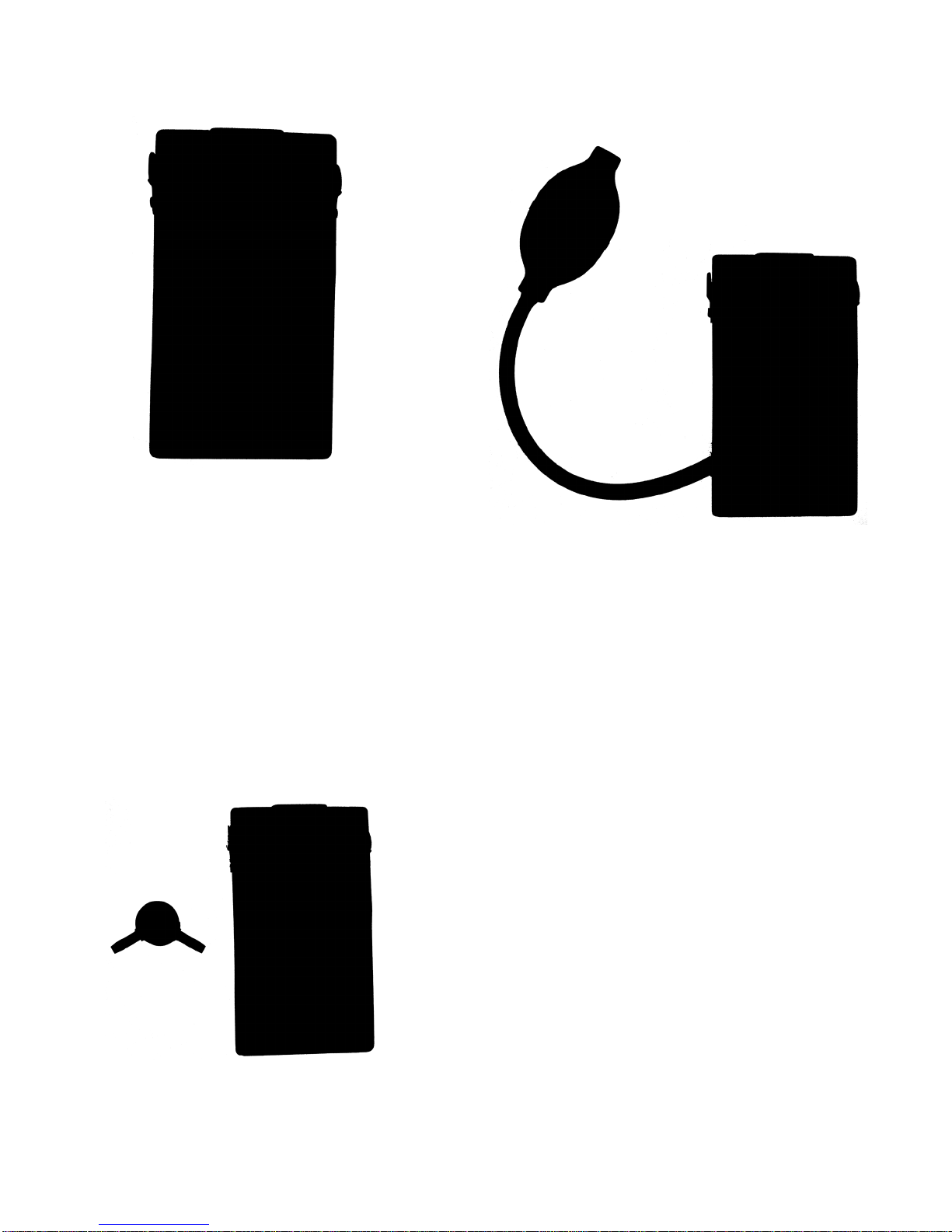
6.Connectthehosettedtotheaspiratorbulb(E)to
oneportoftheowadapter.Theaspiratorbulbis
used to draw a gas sample to the sensor for
measurement.
7.Connectthesteelsamplingprobe(F)tooneendof
therubberhose(G)andconnecttheotherendof
thehosetoremainingportoftheowadapter.
8.Clipthecarryingstrap(H)intotheloopsoneach
side of the Weld GasAnalyzer.
YourAr-Gone Weld Gas Analyzer is now ready for use.
Assembling Your Weld Gas
Analyzer
1. The sensor of your Weld Gas Analyzer is covered
byanadhesivefoamseal(A)whichprotectsit
duringshipment.Removethissealbeforetherst
use since it will hinder the gas reaching the sensor.
2. Switch on your Weld Gas Analyzer using the on/off
switch(B).
3. Adjust the oxygen content displayed to the air oxy-
gen content of 20.90 % using the adjustment wheel
(C).
4. Wait 5 minutes to allow display to stabilize.
Re-adjust if necessary.
5.Connecttheowadapter(D)tothesensoroutletof
the Weld GasAnalyzer.
A
B
C
D
E
F
G
H

5
Instructions For Use
The Ar-Gone Weld GasAnalyzer can be used for all
purge applications where the oxygen content has to be
monitored. This includes purging with purge bladders,
purgedams,siliconediscsystems,solublepurgelms
and papers as well as foam dams and welding
enclosures and chambers.
For the best welding results, Sumner Manufacturing
recommendstheuseofinatablepurgedamsystems
together with your Ar-Gone Weld GasAnalyzer when
welding pipe work and tubular vessels.
1. Your Weld GasAnalyzer can be secured on the
pipe using the carrying strap.
2a.WhenusingaSumnerinatablepurgesystem
together with the Weld GasAnalyzer, the metal
sampling probe may be removed from the
connection hose. The connection hose can then
be directly connected to the exhaust outlet of the
purge system. This guarantees reliable continuous
measurements of the oxygen content in the purge
environment.
2b. Whenusingotherpurgebladders,papers,lms
etc., the metal sampling probe can be inserted
through the weld gap between the two pipes that
arebeingjoined(ifopenrootgapweldingis
applied).
3. Once the Weld Gas Analyzer is connected to the
purge volume, a sample of the gas can be drawn
by squeezing the aspirator bulb.
4. Once the appropriate oxygen level has been
reached(usuallyaround0.1%)andappears
stable, welding can begin.
5. Weld gas samples should be drawn regularly
throughout welding since oxygen penetration can
damage the weld at any stage of the welding
process.
IMPORTANT
Sampling with the aspirator bulb will
pressurize the sensor and can cause
a slight distortion of readings for a
few seconds. This does not reect the
actual oxygen level in the purge and
will return to normal within seconds.
IfconnecteddirectlytoaSumnerinatablepurgedam
system,gaswillowoverthesensorcontinuously.
This allows a constant and close monitoring of the
oxygen level throughout the duration of the weld
without having to draw samples.
Instrument Care
The Ar-Gone Weld GasAnalyzer is a very
accurate instrument and if looked after properly will
give many years of accurate oxygen measurement.
There are very few parts that wear out except sensors
and batteries. The instrument is robust and designed
to be used in the welding environment.
Although it is protected against water it should not be
submerged, left in standing water or left outside
unprotected against weather.
The instrument should be cleaned with warm soapy
water(notimmersed).Nodetergentsorsolvents
should be used on the case or sensor.
Never use the Ar-Gone Weld GasAnalyzer once the
low battery indicator is visible, from this point the
electronics quickly become unstable and will produce
false readings.
DonotsubjecttheAr-GoneWeldGasAnalyzertome-
chanicalshocks.Althoughrobust,theLCDdisplayisa
glass component and can be broken. This is
usually apparent by black areas spreading across the
LCDscreen.
The Ar-Gone Weld GasAnalyzer should be kept in
its case when not in use and should be shielded from
high and low temperatures and long exposure to
sunlight.
Regular Calibration
For greatest accuracy the Ar-Gone Weld GasAnalyzer
should be re-calibrated in normal air every 8 hours.
1. Switch on instrument
2.Removeowadapter
3. Move instrument through air slowly
4. Use calibration knob to set to appropriate reading
forcurrentaltitude(seeOxygenCalibrationTable)
Replacement of Instrument Parts
The case of the Ar-Gone Weld GasAnalyzer is
hermetically sealed to prevent water damage and
contamination. The only parts that can be replaced by
the user are the batteries and sensor.

6
Contact your distributor or Sumner Manufacturing
directly for return instructions. When doing so please
have serial number and purchasing information handy.
Sensor Care
CAUTION
The sensor may be cleaned with warm
water but should never be submerged
in water.
CAUTION
Do not use excessive force to rotate
the sensor into the inner compart-
ment as this can damage the threads.
Sensors prefer a cool and damp environment when
stored.
Never:
• Storesensorsforlongperiodsbeforeuse.
• Subjectsensorstohightemperatures.
• Freezesensors(e.g.leaveon-siteovernight).
• Storeinasealedcontainerwithlimitedorno
oxygen. When this occurs it can take several
hours for the analyzer to stabilize when put back
into use.
• Subjectsensorstophysicalshocks.
• Subjectsensorstoavacuum.
• Submergesensorsinliquids.
• Attempttoopenasensor.
IMPORTANT
Sensors deteriorate very slowly
and near the end of their useful life
may show a drift up or down soon
after calibration. Sensors should be
checked periodically in 100% oxygen
or pure argon.
Sensor Life Expectancy
Sensor life expectancy depends on the amount of
oxygenitisexposedtoandisnotinuencedby
whethertheinstrumentisswitchedonoroff(this
howeverwillaffectbatterylifeexpectancy).Inambient
air sensors will usually work for 24 to 48 months. In an
oxygendeprivedenvironment(i.e.whenusedregularly
duringpurging)thesensorlifewillnormallyincrease.
Correct Sensor Disposal
The sensor contains an electrolyte which is caustic.
Leaking or exhausted sensors should be disposed of
in accordance to local regulations which are usually
similar to the disposal of batteries.
Sensor Replacement
Replacement sensors are supplied by Sumner
Manufacturing.
It is not recommended to stock replacement sensors
since the shelf life and performance will decrease
when they are not in use.
1. Switch off your Weld GasAnalyzer and remove the
owadapter.
2. Remove the battery compartment cover by sliding it
off and disconnect the battery.
3. PlacetheWeldGasAnalyzerface-downonaat
and stable surface and remove the four screws in
thecornersoftherearofthecase.Disconnectthe
back casing from the front casing.
I
7
4. Thesensor(I)iswiredtothecircuitboard.Wires
are connected to the sensor by a pin connector
which can be disconnected by lifting the locking
latch on the connector outwards. The connector
can be lifted off the connector housing which is
located on the circuit board.
5. Unscrew the sensor and remove it.
6. Screw the new sensor in place and re-connect the
pin connector to the connector housing by pushing
it in.
7. Re-attach the back casing to the front casing using
the 4 screws. Take care to feed the battery wires
into their slots in the case.
8. Reconnect the battery and put the battery cover
back in place.
9. SwitchonWeldGasAnalyzertoconrmthatitis
working properly.
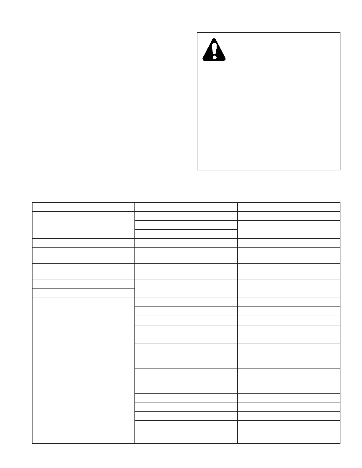
First Aid Procedures:
CAUTION
The electrolyte in the sensor is
caustic, very similar to the
electrolyte in batteries.
If it gets in contact with eyes or skin
it can cause irritation and burning or
stinging.
Wash and rinse affected area with
plenty of water and seek medical
attention if burning persists.
In case of ingestion drink plenty of
cold water, do not induce vomiting
and seek medical attention
immediately.
Troubleshooting
Problem Possible reason Solution
No display Not switched on Switch on
Batteries dead Replace batteries
Batteries inserted incorrectly
Lo symbol appears Low battery Replace batteries
Turns off during welding Turns off automatically after 5
minutes of stable readings Switch on
Zero reading Sensor disconnected, deposit in jack
plug or sensor jack socket Rotate sensor whilst in instrument
Not calibrating to 20.9 Sensor exhausted Replace sensor
Zero reading
Reading drifts
Sensor nearly exhausted Replace sensor
Sensorinowinggastoolong Removesensorfromgasow
Ambient temperature changes Check ambient temperature
Strong winds Shield against winds
Inaccurate reading
Old sensor Replace sensor
Toohighowpressurizessensor Reducegasowifpossible
RF interference Move away frmo RF source
(e.g.radio)
Condensation on sensor face Remove condensate
0.1% oxygen levels cannot be
reached
Sensor not calibrated in air Move calibration wheel in air to
display 20.9
Purge gas is not pure enough Measure purge gas sample directly
Leak in gas hose Check gas hose
Pipe is contaminated Clean pipe from dirt, oil or moisture
Porous purge materials used Usehigherowrateifpurgingwith
foam,paperorsolublelms,use
pure system

8
Oxygen Calibration Table
The Effects of Pressurizing the Sensor
Oxygen sensors usually do not measure the
percentage of oxygen in a mixture of gas but they
measure the partial pressure of oxygen. This is why
Weld GasAnalyzers can sometimes give erratic
readingswhenexposedtotoohighgasoworstrong
winds which cause the sensor to be pressurized.
Feet
(above sea level) Meters
(above sea level) Calibrate Sensor To
0 0 20.90
1,000 305 20.20
2,000 610 19.40
3,000 915 18.70
4,000 1,220 18.10
5,000 1,525 17.40
6,000 1,830 16.80
8,000 2,440 15.50
10,000 3,050 14.40
12,000 3,660 13.30
The Effects of Altitude on the Sensor
Thepartialpressureofoxygeninairis0.209bar(20.9
%)atsealevel.Inhigheraltitudestheairbecomes
thinner and the partial pressure of oxygen in the air
changes.Thecalibrationgureof20.90inaircanbe
adapted to the altitude to ensure optimum accuracy.
Please see table below for more information.
Table of contents
Popular Measuring Instrument manuals by other brands


Topcon
Topcon RL-H3C instruction manual

Graco
Graco IM5 Instructions and parts list

FujiFilm
FujiFilm FUJI DRI-CHEM IMMUNO AU CARTRIDGE vf-SAA Instructions for use

Stahl
Stahl 8485/111-42 operating instructions

Industrial Test Systems
Industrial Test Systems eXact iDip quick start guide

Niigata seiki
Niigata seiki SCDI S Series instruction manual


