Sun Fun Kits V3 User manual

Sun Fun Kits V3, V3 Heated, & V3 RTB Assembly Manual
Revision 1.2

Before you Begin:
Thank you for purchasing your Sun Fun Kits DIY battery kit, the diy battery kits makes
assembling your battery quick and easy and only requires basic tools and hardware. We
recommend having a basic understanding of DC wiring in order to assemble your battery pack.
You will also need the following tools:
● Hex driver set: 3mm, 4mm, 5mm, and 8mm
● Insulated drives for securing bolts
● Thread locking compound (such as blue Loctite)
● Kapton tape 1” to 2” in width
● Double Sided Sticky tape
● Velcro style loop
● DC Voltmeter
● DC Power Supply that is able to charge up battery cells (3.65 volts, 20 Amps)
Optional:
● Electrical Safe Silicone sealant (for those looking to make a water resistant battery)
● Hot glue gun (if you wish to secure wires using this method)
Video Manual:
If you are more of a visual learner, you can view the build process on our official youtube
channel: https://youtu.be/tWm65Pu0GuI
Page: 2 V3 Manual - Revision 1.2

Preparing your battery cells:
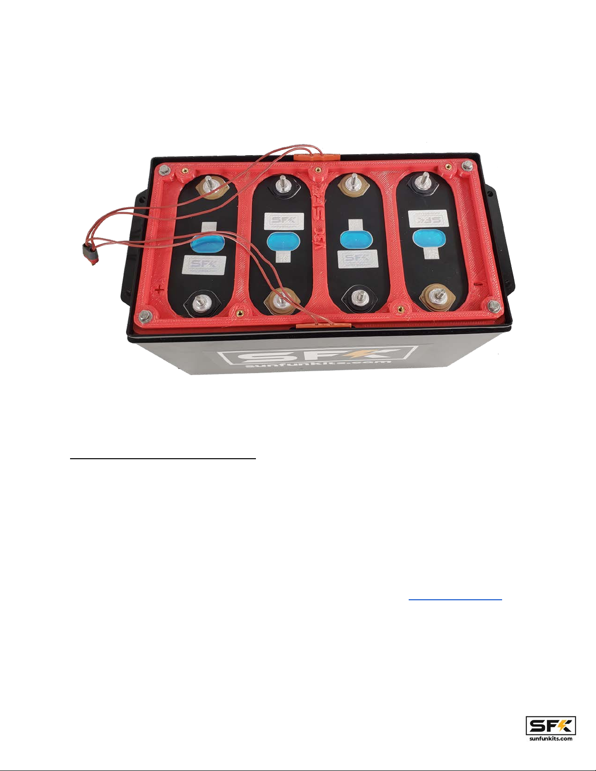
Sun Fun Kits DIY battery kits support various prismatic cells, in this manual we will be using the
EVE LF304 type, however the process is the same for other manufacturers such as CATL,
REPT, Ganfeng and more, the V3 Kit includes spacers and other items to ensure maximum
compatibility for cells in this class (270-320 AH)
Certified Automotive Grade Cells generally do not require balancing; however, you may choose
to balance your cells, we have a video explaining this process.
This process is explained in this tutorial video:
https://www.youtube.com/watch?v=JGbZozzCYvM
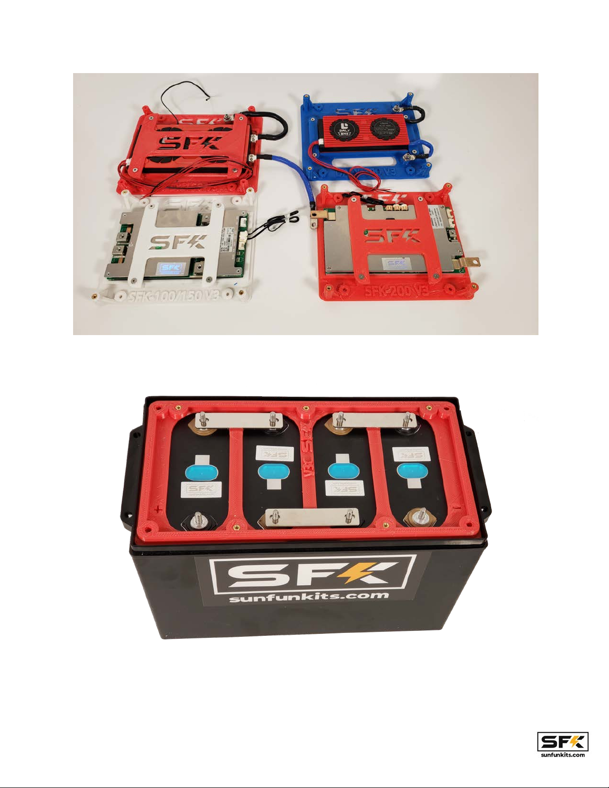
NOTE: if you are using an RTB (ready to build kit) the active balancer will assist in top balancing
your cells, simply assemble your pack, charge the battery at 5-110 amps and within 1-2 hours
your cells should be even balanced. Again, certified cells that are included with your RTB kit will
Page: 3 V3 Manual - Revision 1.2

balance very quickly and the active balancer is included simply to assist balancing during high
amperage charging (over 80 amps).
Assembling your battery cells:
Begin by placing your cells in a series configuration with the left side of the battery having the
positive terminal on the lower left and the negative terminal on the lower right.
Page: 4 V3 Manual - Revision 1.2

Note: you may find some resistance installing your cells, this is because the EPE foam exerts
pressure on the cells to keep them in place. We recommend adding the left most and right most
cells first and then adding the remaining 2 inner cells in the end.
PLEASE MAKE SURE TO PLACE CELLS CORRECTLY IN THE ORDER ABOVE.
Page: 5 V3 Manual - Revision 1.2

Heatead Kits:
If you are building a heated kit, you will have pre-installed silicon rubber heated elements
installed on your case, these will be joined to a t-plug.
The heated kits will provide additional resistance to cells when they are being installed,
however, there is still sufficient space to insert the cells. It is recommended that you do not
install fully charged cells as they will make the process challenging.
Page: 6 V3 Manual - Revision 1.2

Once your cells are in the correct position; it is now time to install your bottom bracket. With our
v3 kits we have made our cell bracket universal and it should fit virtually all cells in the 270-320
AH class. The one differentiating factor is cell height, these can vary from 200mm up to
205.25mm; to address this, the V3 includes 3 sets of shims, find the shim that best matches
your cell height to ensure a level surface.
Page: 7 V3 Manual - Revision 1.2

Install the bottom bracket with the M5 bolts and washers, you can use power tools to assist in
this step. NOTE: Ensure the negative and positive signs on the plate match your cells.
Page: 8 V3 Manual - Revision 1.2

The heated kits look similar to the regular v3 kits except they have a notch cut on the upper and
lower middle to allow the wires from the rubber heating elements to extruded into the main case.
Setting Up Electronics & Cell wiring:
This step involves wiring up your cells, you will need a BMS system and optionally a
supplementary balancing device to complete this step. You will also need to have the
appropriate wiring done to complete the electrical setup. If you are using our SFK-150V2 4s
Bms, all wiring and prep has been done for you; simply bolt onto your components; no crimping
or cutting is necessary.
The V3 kit system supports various BMS devices from manufacturers such as JBD (SFK
Series), Daly, Ant, QUCC, and more. New device support is being added constantly; if you need
a specific mounting plate made, simply contact Sun Fun Kits support at [email protected]
Page: 9 V3 Manual - Revision 1.2

Begin by aligning your buss bars as follows:
Now you will add your series terminals and BMS balancing/monitoring wires as well as the
active balancer wires (NOTE the initial negative post; and the final positive post are shared
between both the active balancer & BMS, all other posts may be separate for each cell) :
Page: 10 V3 Manual - Revision 1.2

NOTE: be sure to use the included washers for the BMS and Active balancer terminals. This is
needed as many cells include serrated nuts that “dig” into the metal, the material on the
balancing and active balancing rings may not be sufficient to handle this, hence a washer above
and below the terminal is recommended.
Page: 11 V3 Manual - Revision 1.2

Your cells should come with the bus bar, terminal studs or welded terminals. Tidy up your install
using electrical tape, zip ties, or velcro strips. Setup the wiring schematic as follows:
black wire = cell 1 negative (0.00 Volts)
1st white wire = cell 1 positive / cell 2 negative bus bar (either post may be used) (3.3 Volts)
2nd white wire = cell 2 positive / cell 3 negative bus bar (either post may be used) (6.6 Volts)
3rd white wire = cell 3 positive / cell 4 negative bus bar (either post may be used) (9.9 Volts)
red wire = cell 4 positive (13.2 Volts)
*The 1st white wire is the wire that is right next to the black wire, the subsequent wires will be
white wire 2, and white wire 3.
The active balancer should be wired:
black wire = cell 1 negative (0.00 Volts)
green wire = cell 1 positive / cell 2 negative bus bar (either post may be used) (3.3 Volts)
yellow wire = cell 2 positive / cell 3 negative bus bar (either post may be used) (6.6 Volts)
white wire = cell 3 positive / cell 4 negative bus bar (either post may be used) (9.9 Volts)
red wire = cell 4 positive (13.2 Volts)
You will need to ensure a tight fit, take care not to strip your battery terminals, if you are using a
torque wrench you will want to tighten down to 6-8 NM. WARNING! Loose terminals will cause
the cells & batteries to fail.
Page: 12 V3 Manual - Revision 1.2

Your voltages should read:
3.3, 6.6, 9.9,13.2 (Nominal Voltage).
If you are using a supplementary balance, you should install this as well, you will need to share
the final negative and positive terminals of the battery for multiple devices. Make sure the
wired main terminals are the ones that touch the cell terminal and only stack the other rings
on top.
All V3 RTB kits include the active balancer, and we highly recommend using it as it
reduces the balancing stress on your BMS and is able to balance out cells significantly
faster during charging.
Once you have verified the wiring has been installed correctly, you can now begin by attaching
the top plate & your BMS.
Installing riser and BMS mounting plates:
After you have verified that your cells are mounted correctly AND VERIFIED they have correct
voltage readings, you can now begin mounting the BMS and other related electronics. Being by
mounting the riser plate by first inserting the active balancer connector into the balancing unit
and then rotate it so that it matches the mounting holes on the main kit plate:
Page: 13 V3 Manual - Revision 1.2

Secure the riser plate using the 3 countersunk M4 screws. We recommend only using hand
tools for this process (despite the youtube videos where the installer and author of this manual
uses an impact hammer… ).
Page: 14 V3 Manual - Revision 1.2

The heated kits will power the silicon rubber heating elements either form dedicated ports on the
BMS, or they will use a temperature active switch that is included with the v3 heated kits. If
using the thermal switch, it has been pre-programmed to provide heating to the battery to
maintain 70 degrees internal case temperature. This will turn on / off as needed to maintain this
thermal threshold. The thermal switch can be adjusted to different temperatures as needed to
suit your requirements.
Page: 15 V3 Manual - Revision 1.2

For heated kits it is recommended to use kapton tape to secure the wires and flap of the silicon
rubber heating elements to the sides of the riser plate.
Page: 16 V3 Manual - Revision 1.2

For heated kits you will connect the T-plug to the thermal switch feed to provide the heating
elements with power. Tuck under the riser plate and secure it using zip ties, velcro strips, or
electrical tape.
With the riser plate installed, it is now time to install the BMS mounting plate. For this install we
will be using the SFK-150V2 BMS; this is the BMS we recommend for our kits and works
extremely well giving the most flexibility and reliability.
Install the m4x25-30 mm bolts on the bottom, and the m4x15mm bolts on the top.
Page: 17 V3 Manual - Revision 1.2

With the plate secured, it is now time to start attaching the terminal cables to the BMS, this will
vary depending on which BMS you are using, for all Sun Fun Kits BMS, we provide the BMS to
you with appropriately sized crimped and ready-to-install wires that you easily attach to your kit.
NOTE: Make sure the balancing lead is NOT connected to the BMS! This will be inserted in a
later step.
Page: 18 V3 Manual - Revision 1.2

Most BMS units will include one or more NTP probes, these can be mounted at the position of
your choice. For The SFK-150V2 BMS unit, you may place these on one of the cells and on a
mounting plate (to get internal case temperature).
Heated kits will include 2 additional terminals that will need to be installed, these will vary based
on the BMS and or thermal switch you are using. For most BMS units, you will attach the
positive to the main battery terminal post on the lid, followed by the negative terminal which is
connected to the output port of the BMS NOTE: it is extremely important that you do not
hook up the thermal switch or silicone heater pads directly to the posts on your cells,
this will by pass your BMS which may cause your cells to drain below the critical 2.5
volts level.
Page: 19 V3 Manual - Revision 1.2

Installing the kit lid and selecting lug mounting options:
With your cables prepped and mounted, it's now time to determine how you will want to mount
your cable lugs to your battery kit. The V3 kits include 2 options: Terminal Studs as well as
flanged top bolts. The terminal stud option is preferred as it offers the best flexibility in terms of
parallel and series connections, however the flanged top bolts provide a height benefit as they
are about one inch shorter.
Page: 20 V3 Manual - Revision 1.2
This manual suits for next models
4
Other Sun Fun Kits Batteries Pack manuals