Sun Fun Kits V4 User manual

Sun Fun Kits V4 Assembly Manual
Revision 1.0

Before you Begin:
Thank you for purchasing your Sun Fun Kits V4 DIY heated battery kit, diy battery kits make
assembling your battery quick and easy and only require basic tools and hardware to assemble.
We recommend having a basic understanding of DC wiring in order to assemble your battery
pack and you will also need the following tools:
● Hex driver set: 3mm, 4mm, 5mm, and 8mm
● Insulated drives for securing bolts
● Thread locking compound (such as blue Loctite)
● Kapton or PET tape 1” to 2” in width
● Double Sided Sticky tape
● Velcro style loop
● DC Voltmeter
● Standard scissors
● 90% isopropyl alcohol.
● Adjustable DC Power Supply that is able to charge up battery cells (3.65 volts, 20 Amps)
if manually balancing or standard 13.6v to charge the battery.
● 300-400 grit sandpaper
Optional:
● Electrical Safe Silicone sealant (for those looking to make a water resistant battery)
● Hot glue gun (if you wish to secure wires using this method)
Page: 2 V4 Manual - Revision 1.0

Preparing your battery cells:
Sun Fun Kits DIY battery kits support various prismatic cells, in this manual we will be using the
EVE LF304 type, however the process is the same for other manufacturers such as CATL,
REPT, Ganfeng and more, the V3 Kit includes spacers and other items to ensure maximum
compatibility for cells in this class (270-320 AH)
Certified Automotive Grade Cells generally do not require balancing; however, you may choose
to balance your cells, we have a video explaining this process.
Page: 3 V4 Manual - Revision 1.0

This process is explained in this tutorial video:
https://www.youtube.com/watch?v=JGbZozzCYvM
NOTE: if you are using an RTB (ready to build kit) the active balancer will assist in top balancing
your cells, simply assemble your pack, charge the battery at 5-20 amps and within 1-2 hours
your cells should be even balanced. Again, certified cells that are included with your RTB kit will
balance very quickly and the active balancer is included simply to assist balancing during high
amperage charging (over 80 amps).
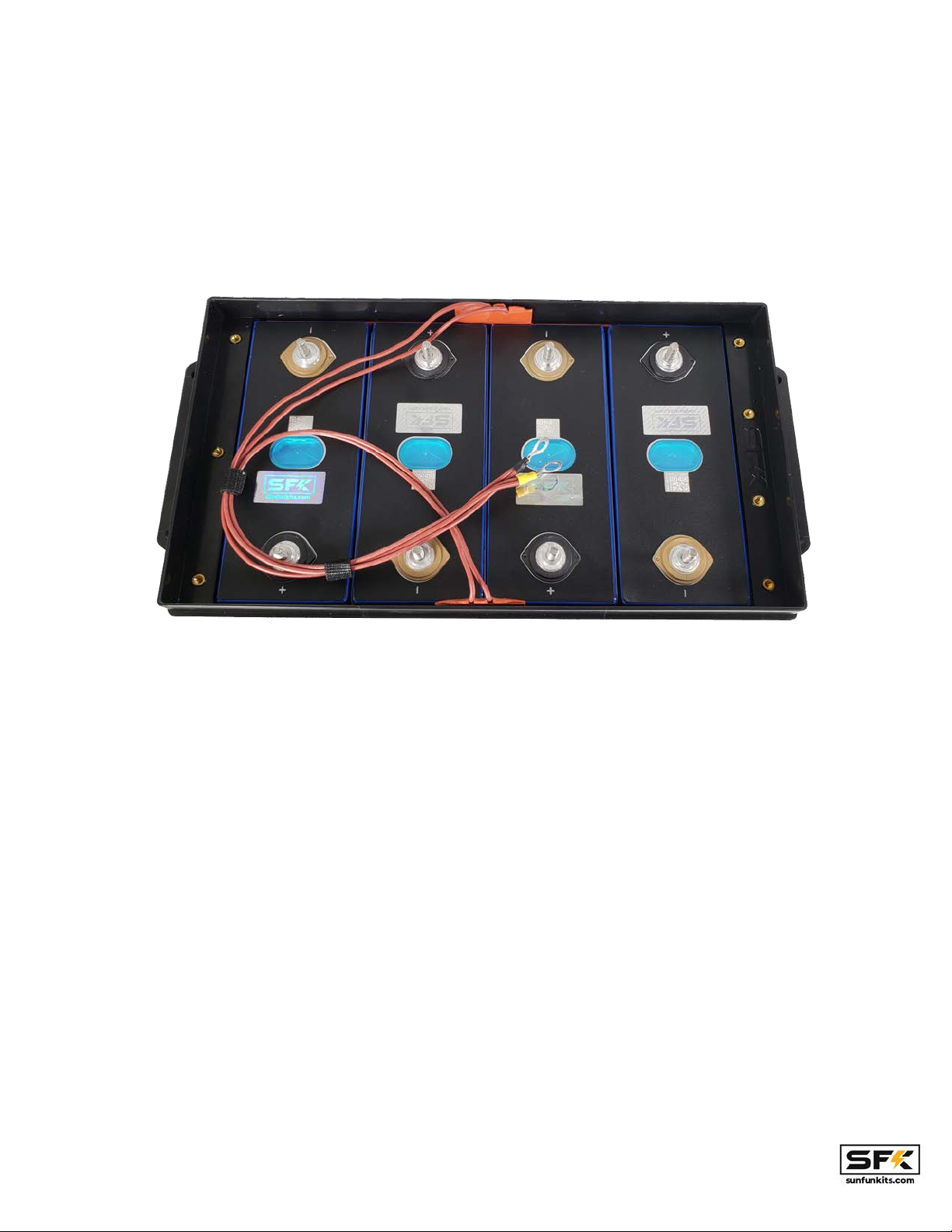
Assembling your battery cells:
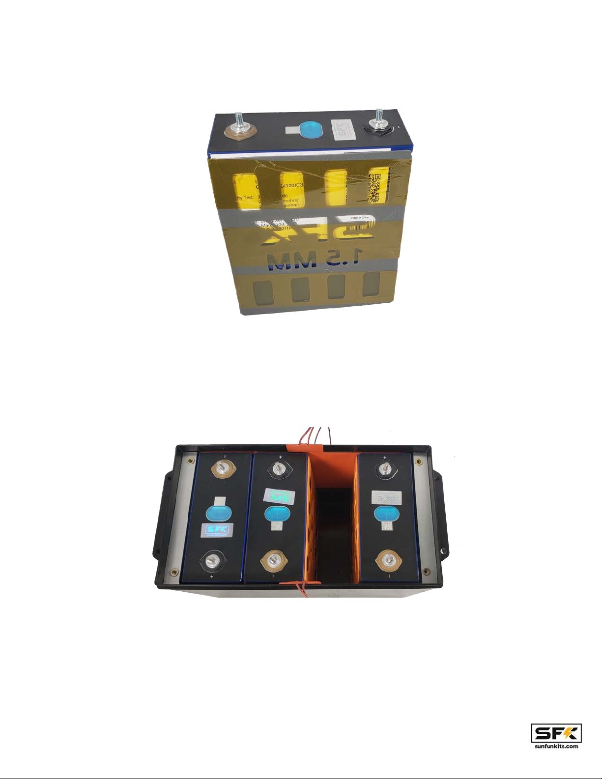
Starting with version 4 we are now including different cell shims or spacers, this allows users to
have a nice tight fit while also adding a third layer of insulation between cells. Version 4 includes
1 set of 1.5mm and 1.0mm shims (3 pieces each). The shims should be placed between the
inner cells and most installs will use about 1-3 shims (depending on the install method). For Sun
Fun Kits certified cells (LF280K, REPT 280, and LF304) you should be able to use 3 x 1.0 mm
shims to complete the install and have a nice tight fit, however for maximum pack longevity and
vibration isolating 3x 1.5mm shims will work the best.
Page: 4 V4 Manual - Revision 1.0

If you find difficulty installing the 1.5mm shims you may go down to 1.0 MM shims, you can mix
and match the 1.0 and 1.5mm shims as needed to suit your install preference.
Note: Based on customer feedback, we are now recommending you use the 1.00 shims
for the install, the 1.5mm shims should be used only by experienced installers.
Sidewall Heating Setup (Basic setup):
Version 4.0 includes 2 options for cell heating, a sidewall heating option as well as an
in-between cell heating option. Both options will allow you to heat up your battery for low
temperature charging (below freezing), however the sidewall heating method is generally an
easier install method. Note: both options will require the use of Kapton / PET high
temperature tape.
Version 4’s basic heating element includes dual heating pads on the inside walls of your kit. This
provides good heating and will raise the inside temperature of your case evenly. This method is
quite easy to install and is the only method that should be used if you are using grade B cells or
swollen cells as it provides the most amount of spacing for the cells.
Begin by placing your cells in a series configuration with the left side of the battery having the
positive terminal on the lower left and the negative terminal on the lower right.
Page: 5 V4 Manual - Revision 1.0

*Image shown is from the V3.5 Kit, but the install process is the same on V4.
Test fit the cells to get an idea of the installation; you will now need to prepare the cells with
shims. For this you have 2 options:
1) Place the cells and then insert the shims as you install the cells
2) Recommended: Tape the shims with Kapton tape to the cells and insert them together
into the case.
Page: 6 V4 Manual - Revision 1.0

Note: You will want to have the textured side of the shim facing the cell you installed, with the
smooth side facing outward. This will ensure the shim stays in place while you install cells.
*Image shown is from the V3.5 Kit, but the install process is the same on V4.
Page: 7 V4 Manual - Revision 1.0

Note: you may find some resistance installing your cells, this is because the EPE foam exerts
pressure on the cells to keep them in place; this is why we recommend adding the left most and
right most cells first and then adding the remaining 2 inner cells in the end as shown in the
picture below:
PLEASE MAKE SURE TO PLACE CELLS CORRECTLY IN THE ORIENTATION ABOVE.
V4 kits support various cells and depending on your cell height you may or may not need cell
spacers. For the LF280K, REPT 280 and LF304 cells sold by Sun Fun Kits, you will use the
1.5mm spacer on top of the case molded in ledges to raise the height of the support so that it
matches the cell. If you are using EVE LF280N or other cells that are 200mm tall you will need
the 2.5mm cell booster to raise the height of your cells.
Note: Starting with version 4, we are including a “Cell Puller” which will allow you to pull out your
cell if you have oriented incorrectly. The V4 kit holds cells tightly in place and this can be
challenging if you need to correct the orientation of a cell.
Page: 8 V4 Manual - Revision 1.0

*Take note of the 1.5mm Shims, these are needed to ensure a level surface for the main cell plate.
The side-mounted silicon heating pads will provide additional resistance to cells when they are
being installed, however, there is still sufficient space to insert the cells. It is recommended that
you do not install fully charged cells as they will make the process more challenging.
Once your cells are in the correct position; it is now time to install your cell plate. With our v4 kits
we have made our cell bracket universal and it should fit virtually all cells in the 270-320 AH
class.
Version 4 changes the 4x m5 screws mounting method in favor of 7x m4. This method provides
us with superior holding power and also ensures that the plate can not be mounted incorrectly
as 1 side has 4 mounting points while the other has 3. NOTE: Ensure the negative and positive
signs on the plate match your cells.
The side notches on the plate provide the opening channel to route your heating pad wires.
Page: 9 V4 Manual - Revision 1.0

Setting up heating using heated cell-separators (advanced):
The cell separator option is the more advanced heating option available in version 4 kits, this
allows 2 cells to be heated by a single silicon rubber heating element; 2 elements in total are
able to heat all 4 cells. The direct contact nature of this option means that the cells will heat up
faster so there is a potential of having a bigger delta in temperature between the cells and the
rest of the case. However, this method will provide for superior cell heating.
Page: 10 V4 Manual - Revision 1.0

Locate the 2 silicone rubber heating elements and attach them to your cells using KAPTON
TAPE or PET/Polyester high temp Tape. DO NOT USE SCOTCH™ or other forms of plastic
tape, KAPTON (PET or Polyester BASED) is required to handle the heat being generated by the
silicone pads.
Once attached you will be able to place this into your battery case (note in this case there are
no heating elements on the sides of the case walls).
As with the non-heated kits, place the leftmost and rightmost cell first, ensuring they have the
correct polarity before installing.
Page: 11 V4 Manual - Revision 1.0

For the inner 2 cells you will use a shim for one of the cells to provide the final cell separator for
the kit, you can select from either the 1.0m or the 1.5mm shim depending on how tight you want
your install to be (the tighter the better for most installations, however, we recommend going
with the 1.0mm shim if this is your first kit).
Note: for the in-between cell heating install you will only need a single cell shim as the
heating pads act as shims as well and being made out of silicone rubber are excellent
electrical insulators.
The textured side of the shim should be facing the cell while the smooth side should be
exposed.
Some resistance is normal as this will ensure a tight fit and make sure your cells do not move
around, installing the last cell can be a bit challenging, take your time and press into the side
foam if you need to to increase the area for the last cell to be inserted in.
Page: 12 V4 Manual - Revision 1.0

*Once you have the base of the cell in, you will need to rock it from side to side to fully insert it into the case.
After inserting the cells you will have 2 heating pads and 1 shim, now you can place the cells
spacers (shown above as the green pieces that sit on top of the molded ledges) and proceed
with mounting the v4 main plate (note the cell spacers are needed for cells that are 204mm or
Page: 13 V4 Manual - Revision 1.0

taller, if you have 200mm tall cells you will not use them install you will place the 2.5mm cell
booster beneath your cells to raise the height of your cell to match the molded ledge).
Route the heated cell-separator wires through the dedicated slots on the v4 kit. You will then
need to crimp the heating pad wires together. The V4 kit with in-between-cell heating option
includes 2 terminal lugs for this: an 8mm diameter yellow lug and a 6mm diameter black lug.
Take 1 wire from each pad and crimp it together with the yellow lug, and the other 2 wires and
crimp to the black lug. Note: you must make sure each lug has a wire coming from a
different heating pad, do not crimp the wires from the same pad together as 1 lug or it
will not complete the heating circuit.
Page: 14 V4 Manual - Revision 1.0

Setting Up Electronics & Cell wiring:
This step involves wiring up your cells, you will need a BMS system and optionally a
supplementary balancing device to complete this step. You will also need to have the
appropriate wiring done to complete the electrical setup. If you are using our SFK-200V2 4s
Bms, all wiring and prep has been done for you; simply bolt onto your components; no crimping
or cutting is necessary.
The V4 kit system will be focusing exclusively with the SFK-200V2 BMS initially, with support for
the SFK-150V2 and other BMS units being added in the future.
Page: 15 V4 Manual - Revision 1.0

With version 4, we are now using a 3mm / ⅛” thick Garolite FR4 / fiberglass main plate along
with aluminum standoffs with custom 3d printed holders to secure the BMS in place. This
provides us with superior heat resistance, increased strength, and greater dimensional accuracy
for our kits. Many of these changes are in response to queries and suggestions form our
customers, we would like to thank you for your input .
Page: 16 V4 Manual - Revision 1.0

Note: Before beginning this step it is EXTREMELY IMPORTANT that you clean and wipe
down all of your bus bars, washers, terminals and battery post with 90% isopropyl
alcohol. Dirty terminals and connections will result in improper readings and poor
results.
Begin by placing your bus bars in the orientation shown below and then place a m6 washer on
top of the bus bars, this is needed to provide an even and stable base for your BMS terminals.
Page: 17 V4 Manual - Revision 1.0

Now you will add your series terminals and BMS balancing/monitoring wires as well as the
active balancer wires (NOTE the initial negative post; and the final positive post are shared
between both the active balancer & BMS, all other posts may be separate for each cell). Place
the BMS ring terminal directly over the main lug and then the active balancer ring on top of it.
NOTE: be sure to use the included washers for the BMS and Active balancer terminals. A
washer should be placed above each bus bar, for version 4 we are now including M8 nylon lock
nuts as they provide excellent anti-vibration capabilities without needing thread locking
compound.
Please note your BMS wires should be routed to the positive terminal and the active balancer
wires should be routed to the negative terminal.
Your cells should come with the bus bar, terminal studs or welded terminals. Tidy up your install
using electrical tape, zip ties, or velcro strips. Setup the wiring schematic as follows:
Note: CAUTION!!! In many prismatic cells the positive terminal is colored black and the
negative terminal is colored brown! Please double check your cells with a volt/multimeter
before continuing.
black wire = cell 1 negative (0.00 Volts)
1st white wire (green lug) = cell 1 positive /(3.3 Volts)
2nd white wire (yellow lug)= cell 2 positive /(6.6 Volts)
3rd white wire (blue lug) = cell 3 positive /(9.9 Volts)
Page: 18 V4 Manual - Revision 1.0

red wire = cell 4 positive (13.2 Volts)
*The 1st white wire is the wire that is right next to the black wire, the subsequent wires will be
white wire 2, and white wire 3.
The active balancer should be wired as follows we will be using the negative terminal post for
most of the cells for this harness:
black wire = cell 1 negative (0.00 Volts)
green wire = cell cell 2 negative (3.3 Volts)
yellow wire = cell 3 negative bus bar) (6.6 Volts)
white wire (with blue lug) = cell 4 negative bus bar) (9.9 Volts)
red wire = cell 4 positive (13.2 Volts)
You will need to ensure a tight fit, take care not to strip your battery terminals, if you are using a
torque wrench you will want to tighten down to 4-6 NM. WARNING! Loose terminals will cause
the cells & batteries to fail.
You will align the balancing wires towards the main lugs leaving the center area clear for the
active balancer.
Page: 19 V4 Manual - Revision 1.0

USE EXTREME CAUTION! THE BLUE WIRE SHOULD NOT TOUCH THE POSITIVE
TERMINAL OF THE FIRST CELL OR IT WILL ARC AND DESTROY THE CELL. You should
consider covering this terminal with kapton tape or other insulating material to ensure
that it can not short circuit the first cell.
Page: 20 V4 Manual - Revision 1.0
Other Sun Fun Kits Batteries Pack manuals
Popular Batteries Pack manuals by other brands

XD COLLECTION
XD COLLECTION P322.61 Series manual

AIMS Power
AIMS Power LiFePO4 LFP12V50B instruction manual

Atronix
Atronix AX2.88kWhBM Installation and operation manual

Tripp Lite
Tripp Lite BP480V140 Specifications

Tripp Lite
Tripp Lite SmartPro BP48V60RT3U owner's manual

Power-Tronics
Power-Tronics ABF10 manual